Electronics Design
I love electronics assignments because I really learn new things that I’ve never done before. I AM REALLY EXCITED TO DESIGN MY PCB !
Group Assignment:
We had to test the equipment in our lab to observe the operation of a microcontroller circuit board (in minimum, check operating voltage on the board with multimeter or voltmeter, and use oscilloscope to check noise of operating voltage and interpret a data signal).
You can check the group assignment in this link : Electronics Design Group Assignment.Individual Assignment:
In electronics design assignment, we were asked to do the following :
After Prof. Neil's session, I checked the tutorial to know the steps on how to make circuit board design. There are different software that we can use to design the electronics board. I chose Eagle software to make my own PCB. Although I have never used it before, I am always enthusiastic about learning a new software. I also checked the available circuits., I am going to use the Attiny44 based microcontroller circuit.
To design the electronics, we have to follow the steps:
1. Download EAGLE software.

What is EAGLE Software?
“ EAGLE is a scriptable electronic design automation (EDA) application with schematic capture, printed circuit board (PCB) layout, auto-router and computer-aided manufacturing (CAM) features”
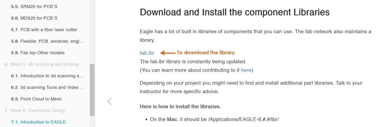
2. Download FAB library.
Eagle software has many components. I downloaded the fab library to add more components as it is being used to build FAB circuits. This library was created by fab network.
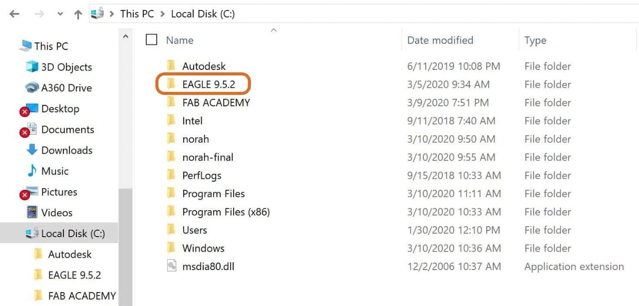
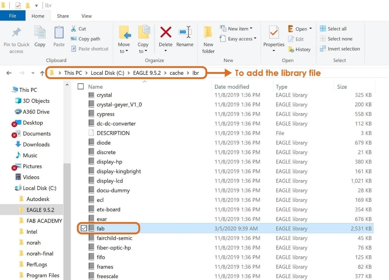
3. Install the library to Eagle.
To install the library we have to follow some steps ( for windows ) :
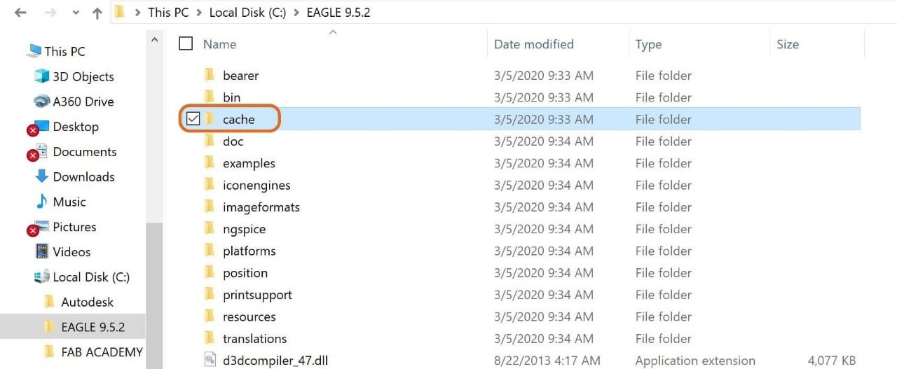
Go to C: > Program Files > EAGLE 9.5.2 > Catch > lbr > Add the library file.
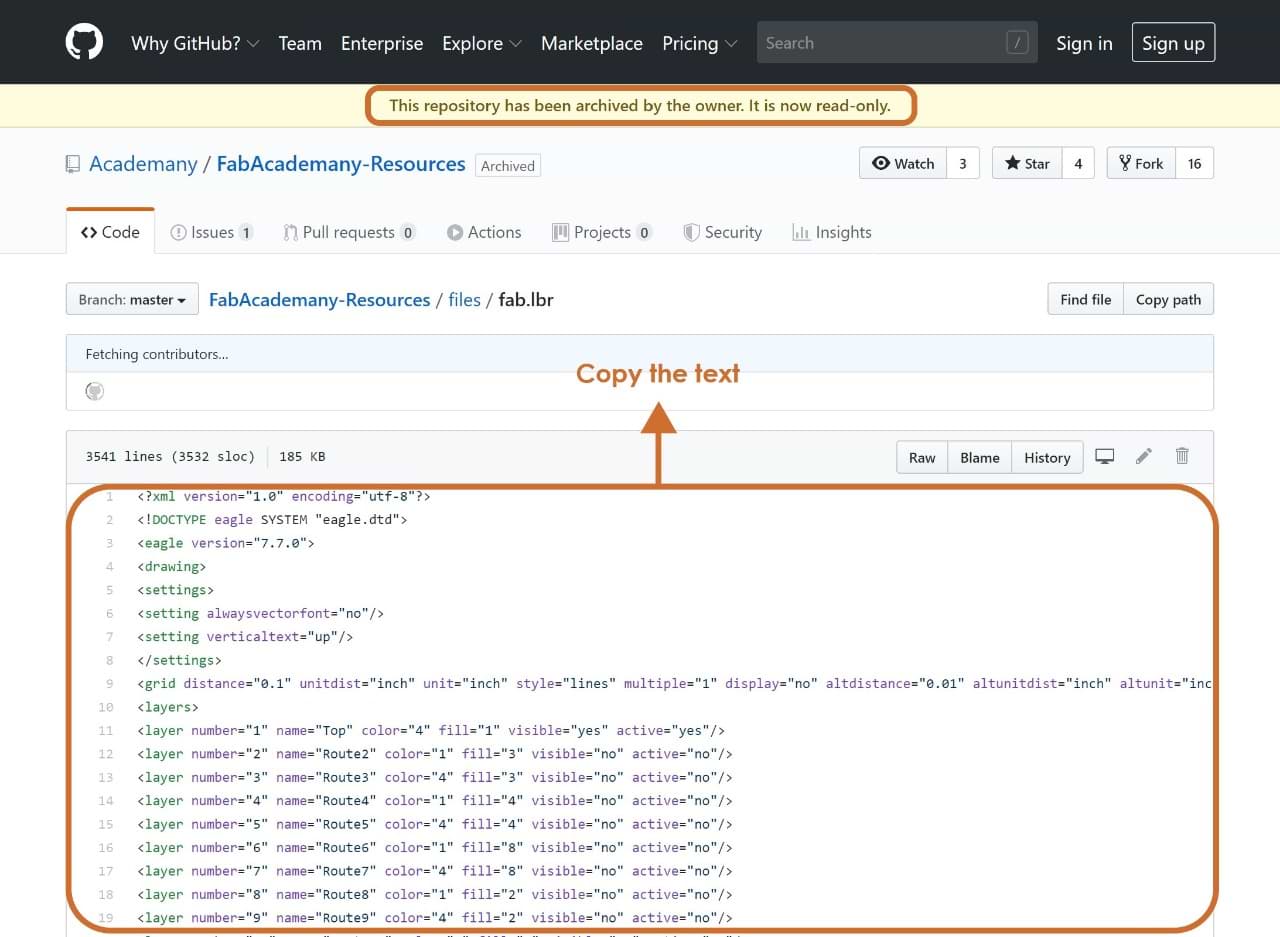
We faced an issue when we installed the fab library. When we open the library in eagle software, it looked like it is read only. Our instructor helped us to solve the problem by doing the following:
To solve this issue we followed these steps:
1. Open the fab library from Github and copy the text.
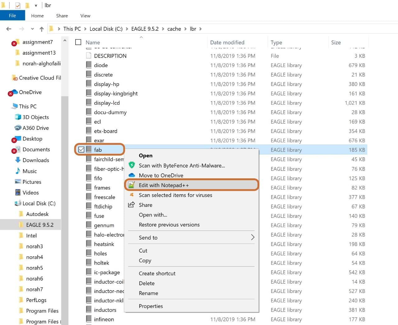
2. Go to local disk C: file > Program Files > EAGLE 9.5.2 > Catch > Lbr > Fab library > Right click > Edit by notepad++ > Delete the previous text > Paste the new text > Save it.
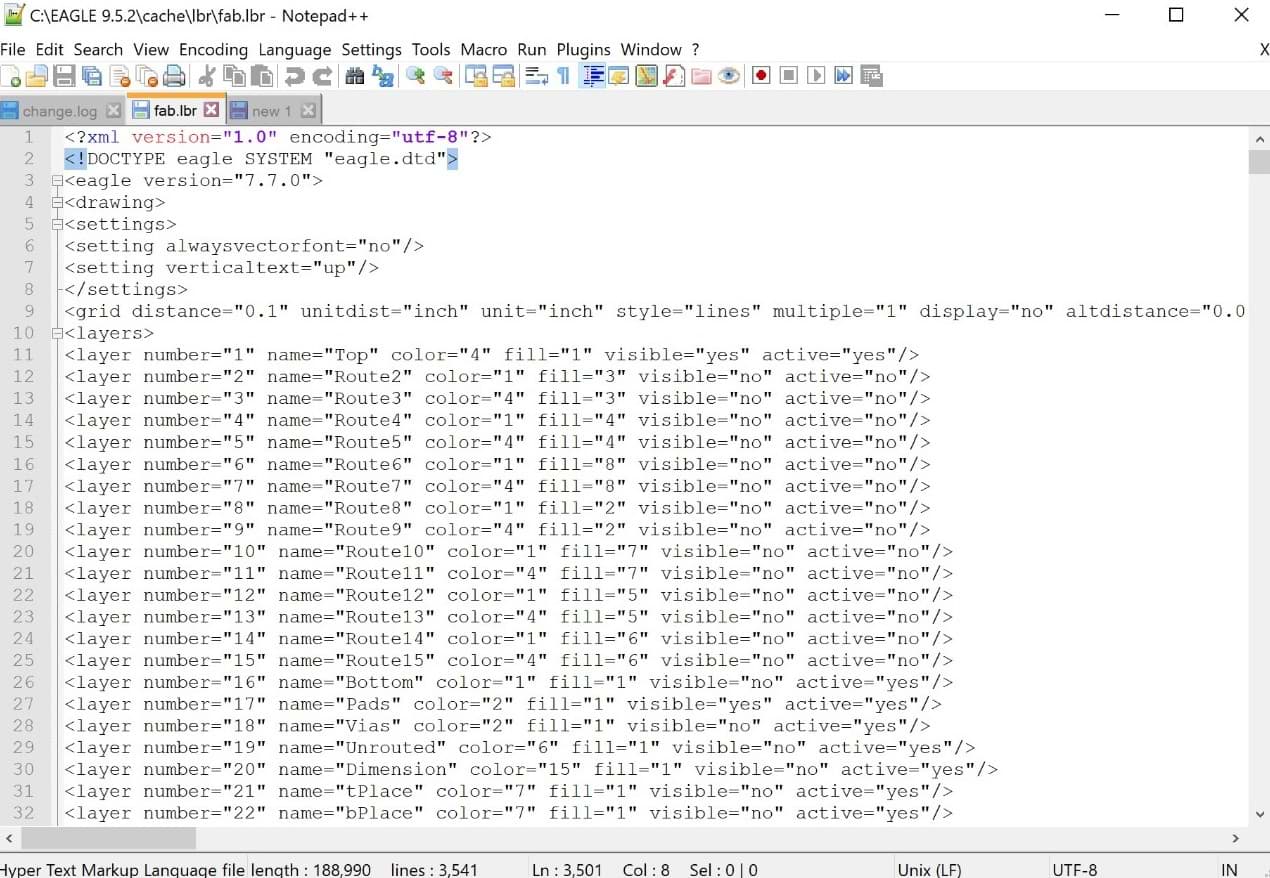
Wow, we solved it !
I can now redraw the schematic echo hello-world board. I chose Attiny44-SSU to build my own PCB. The main components that I’m going to use are:
Let’s design the PCB !
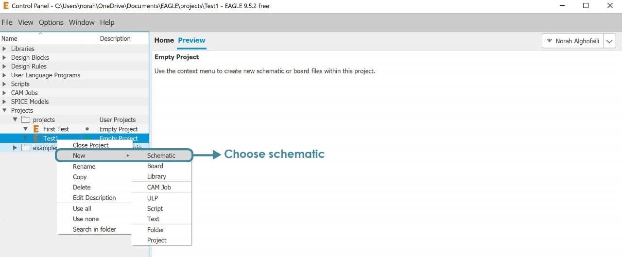
Open Eagle Software then go to > File > Project > New > Rename the project > Schematic
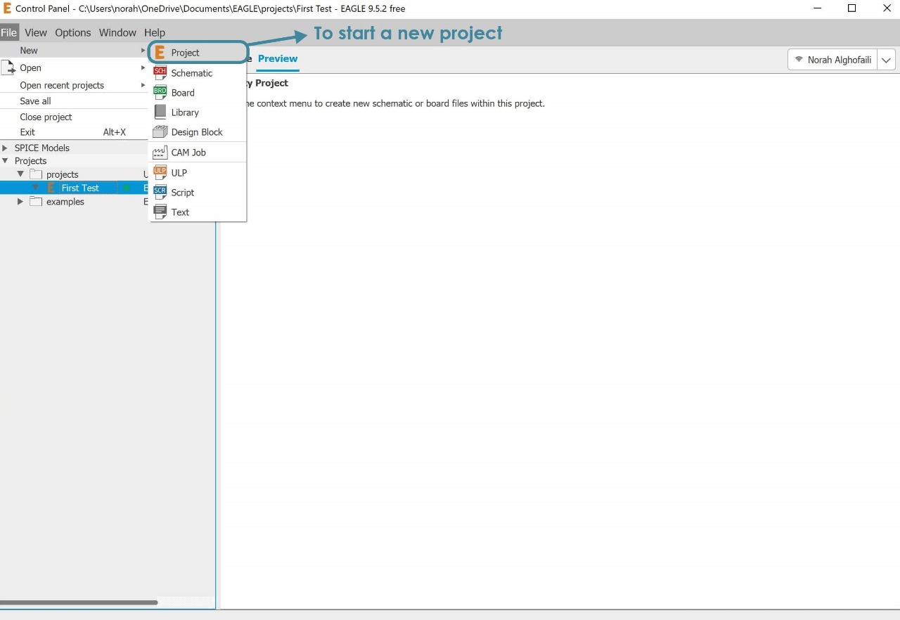
To design the board, eagle software has two Windows :
1. Schematic (.sch) Window : This window helps to add the components and connect them with each other. It also helps to add value if needed.
This is the interface of the schematic:
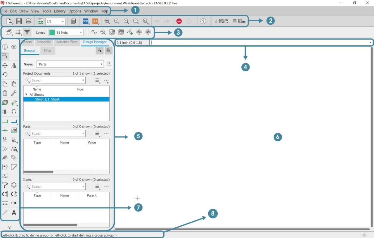
The main parts:
- 1. Menu bar.
- 2. Toolbar.
- 3. Parameter toolbar.
- 4. Command line.
- 5. Coordinate display.
- 6. Working Area.
- 7. Command toolbar.
- 8. Status bar.
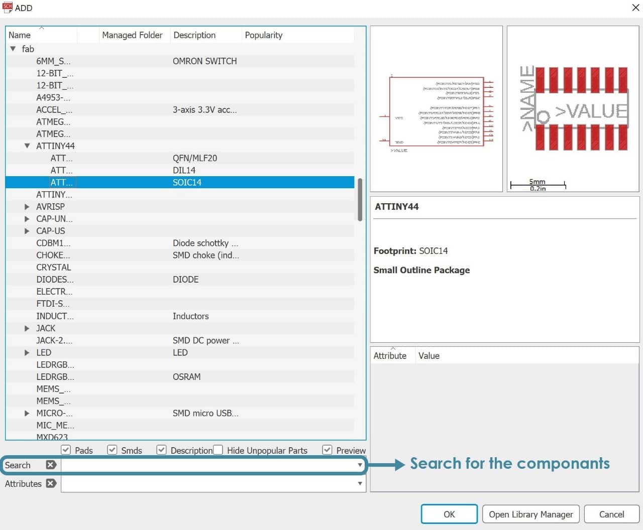
To add components > Go to add part > then add all the required components.
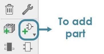
I selected fab library to add the parts needed, because it has the exact components and dimensions, for example: our SMD components have the code 1206 which refers to the size.
I’m going to add all the required components.
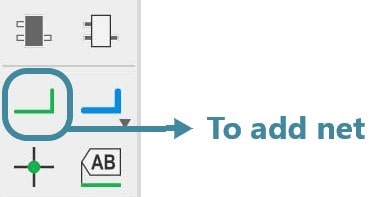
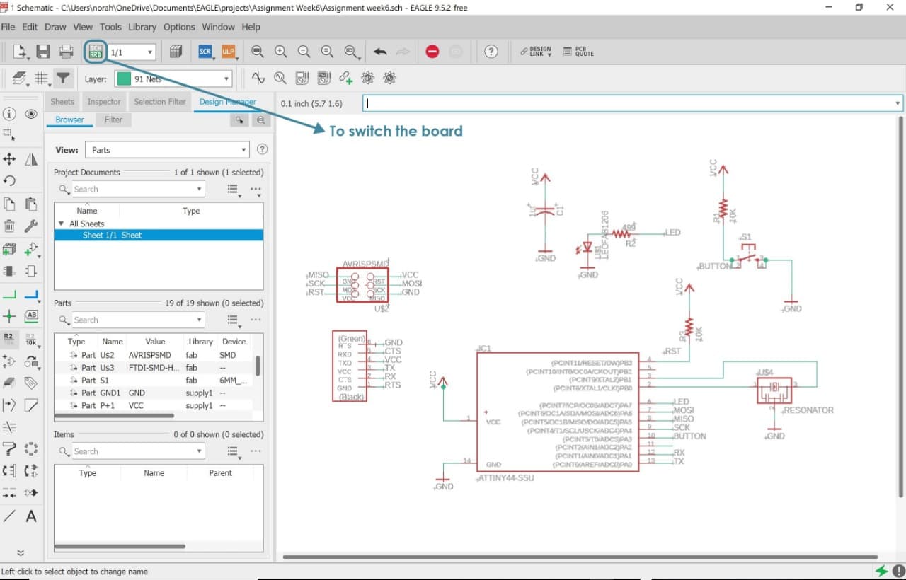
After I added all the components, I followed the drawing (from FAB academy tutorial) to connect the components with each others by using net/wire.
Then I switched the bo ard to ‘board layout window’ to finalize the circuit.
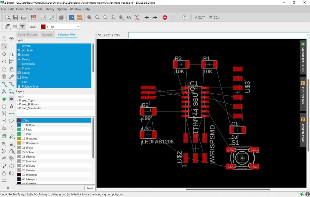
Board Layout (.brd) window : After we finished inserting the schematic comp onents and connected them together, we opened the board layout window to redesign and organize the components by drawing wires between them to get the actual board that we will mill.
This is the board layout window:
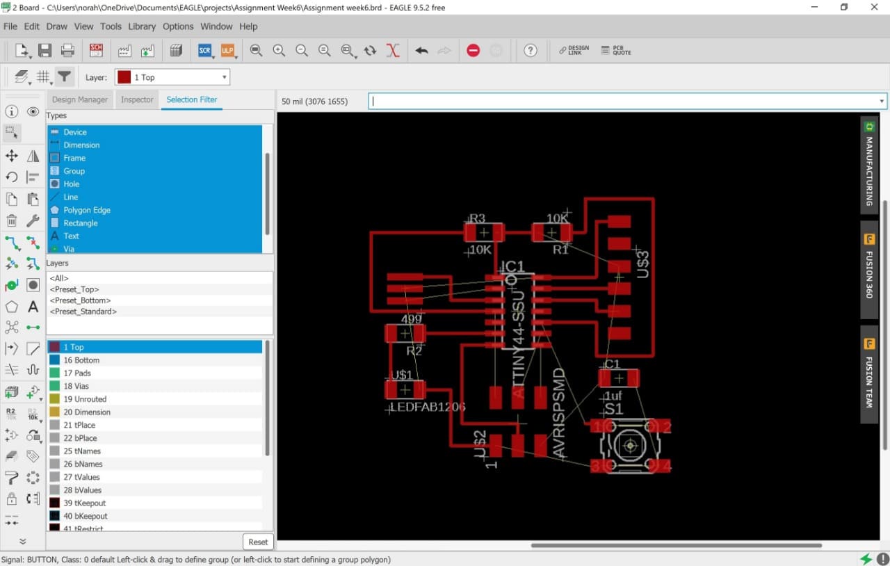
Start to drag the components to the boarded area to arrange and link them to each other.
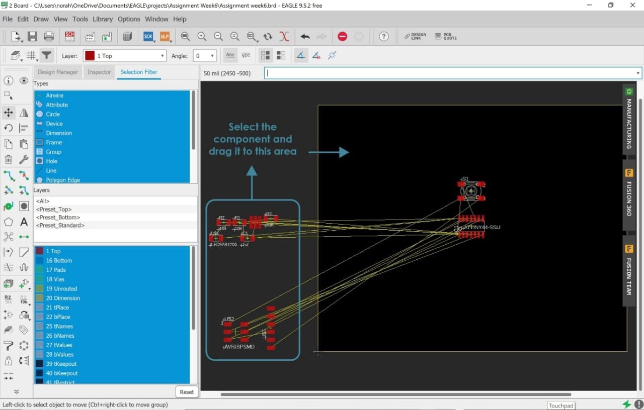
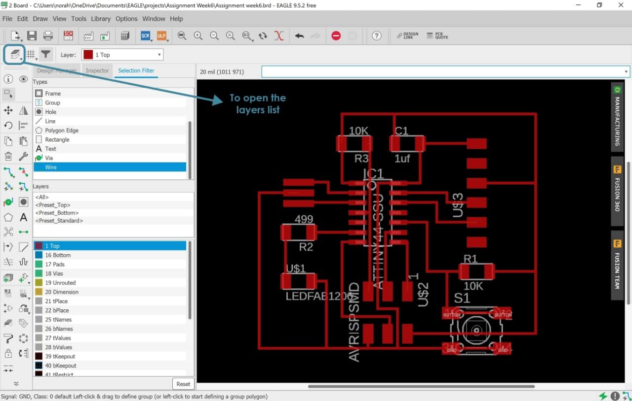
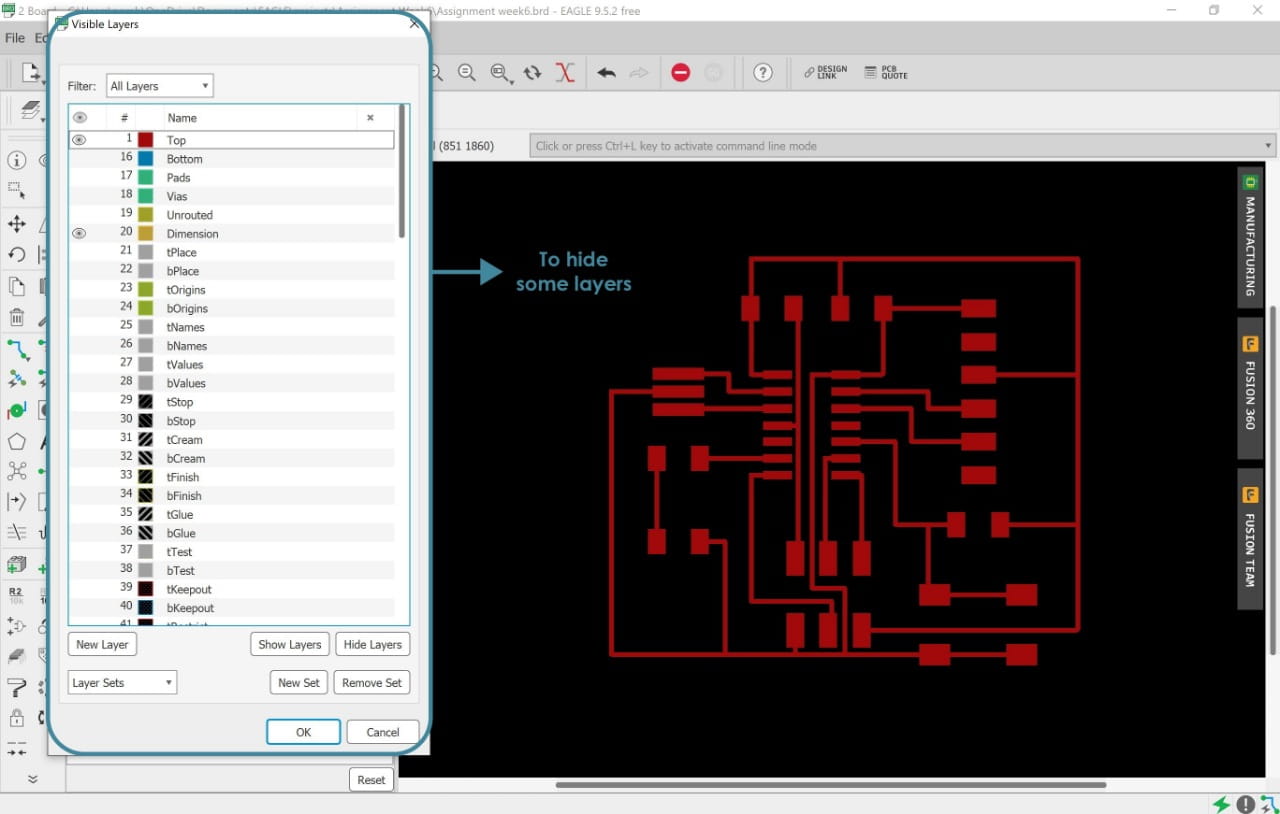
After we were through with this step, we have to hide some layers that we did not need.
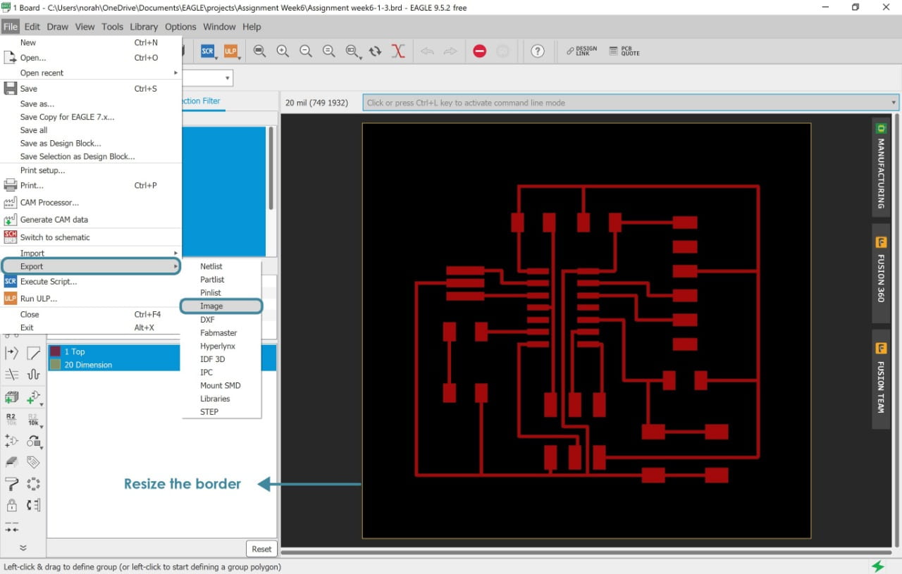
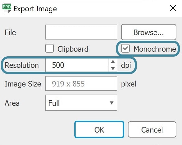
Afterwards, I saved the drawing by going to File > Export > Image > Write the file name > Browse > Save ( as PNG ).
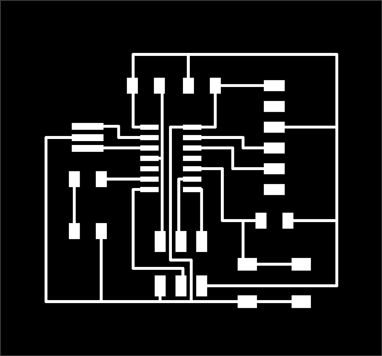
The final result !
Is this the last step before milling the board ? NOOO !!
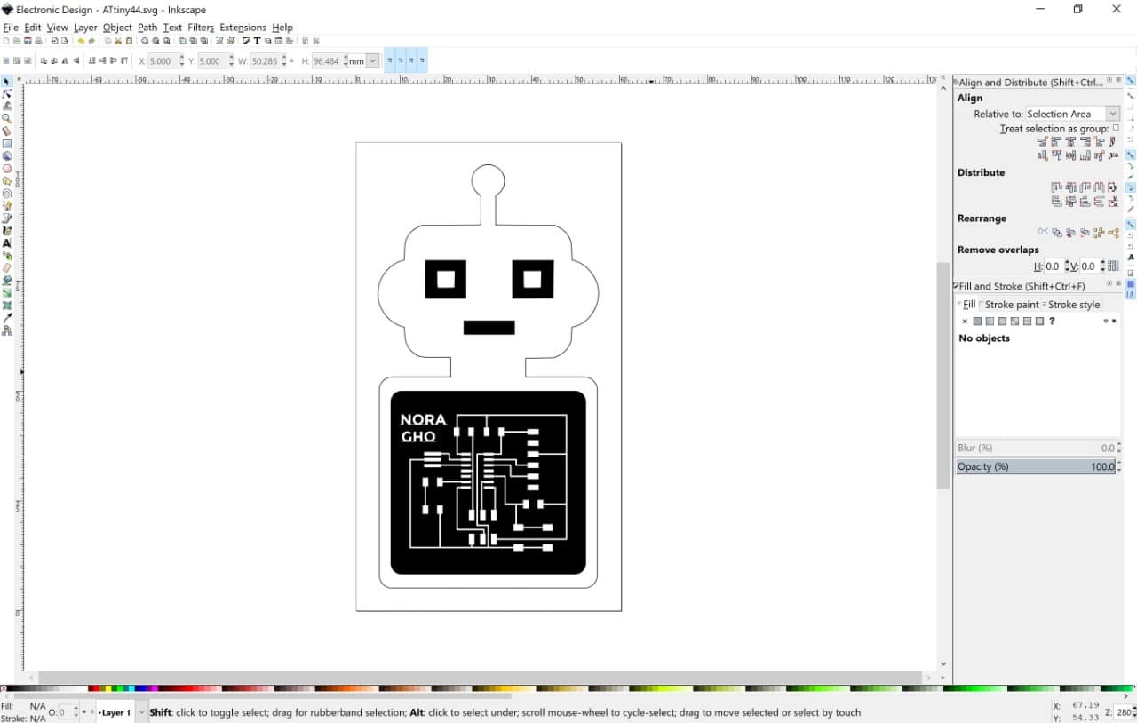
The last step is to convert the drawing from raster to vector by using a trasebit map in Inkscape.
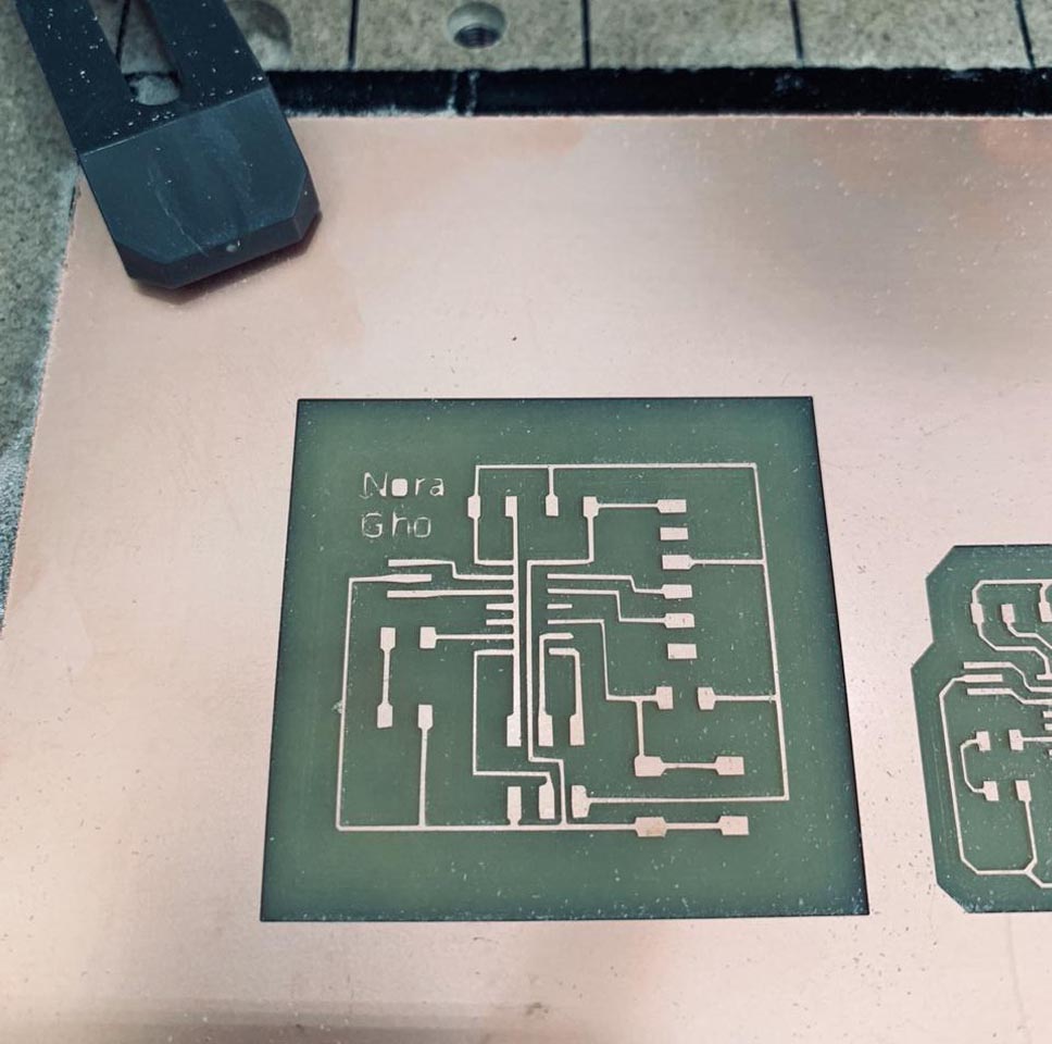
Afterwards, I decided to design an outline for the PCB to be more creative. I chose the robot to be the outline shape of my PCB. I also wrote my name on it =).
Now let’s mill the PCB !
I’m going to use a Carvey milling machine to mill my PCB. I have talked in detail about this machine earlier. If you want to know about this machine, please check the Electronic Production Assignment.
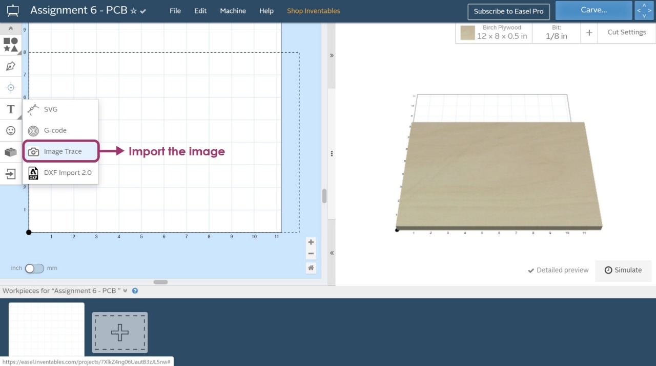
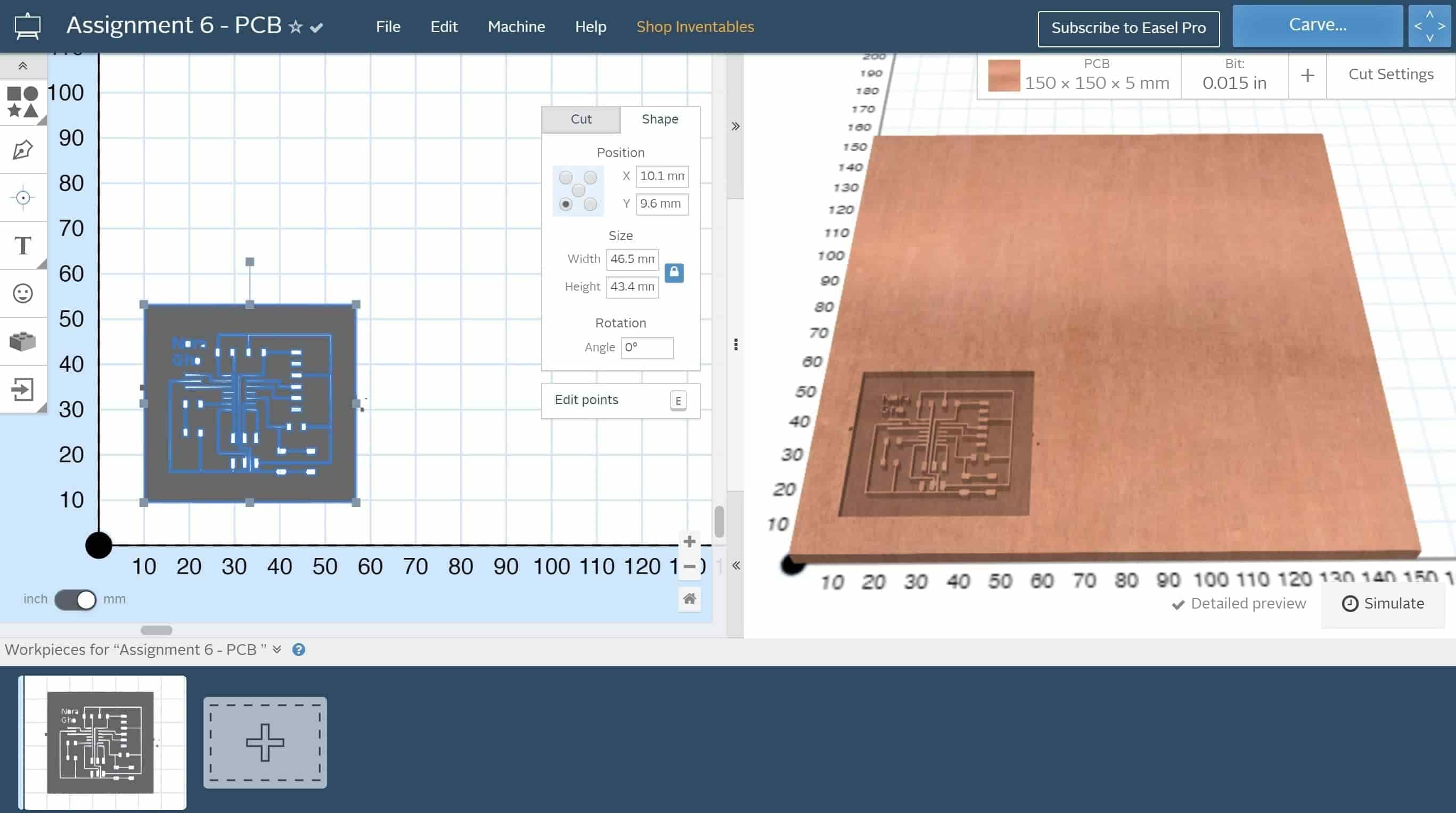
Easel software:
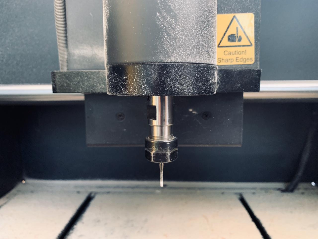
The milling bit:
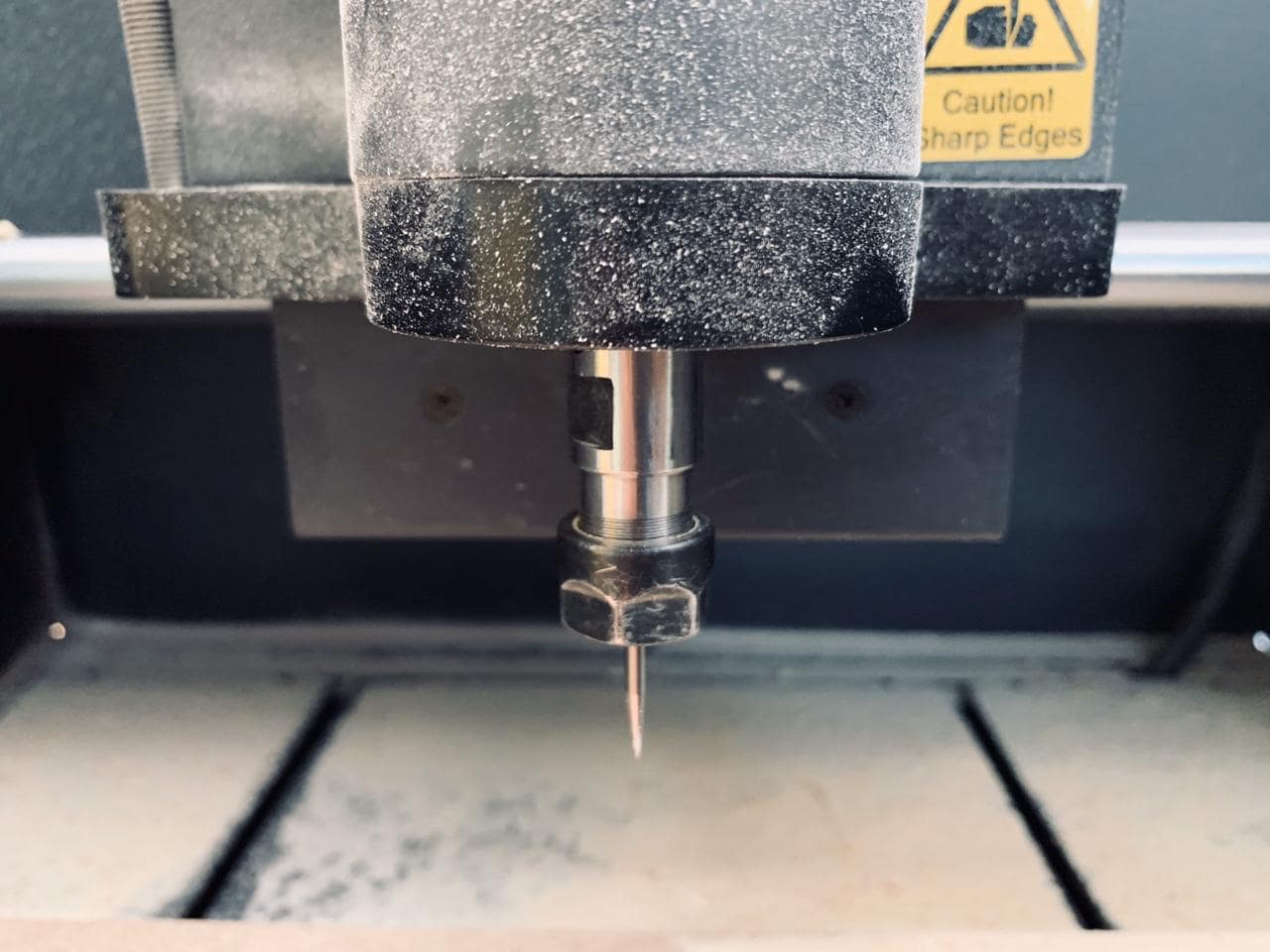
I was faced with a problem while milling the PCB. The problem was that the bit could not reach down to drill the material. This happened because the base was not on the same level. So, I changed the base and made sure that it's in the same level.
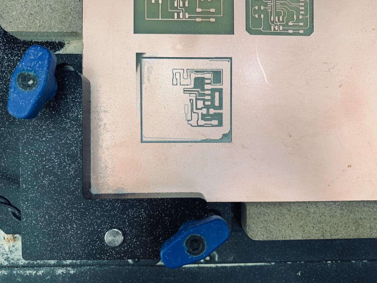
This is the final result of the drilling !! Wow, it’s so neat, isn’t it ?
The cutting bit:
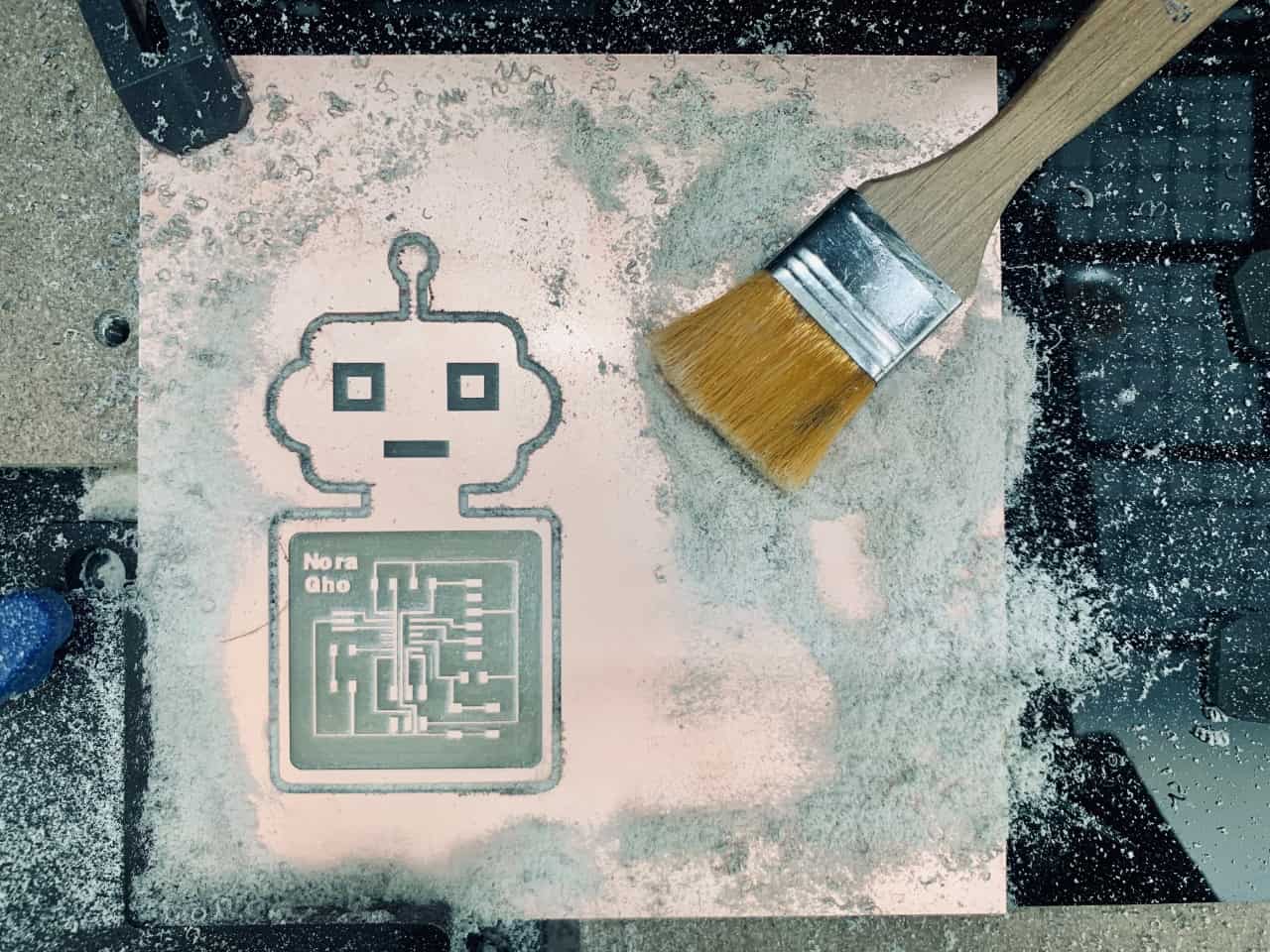
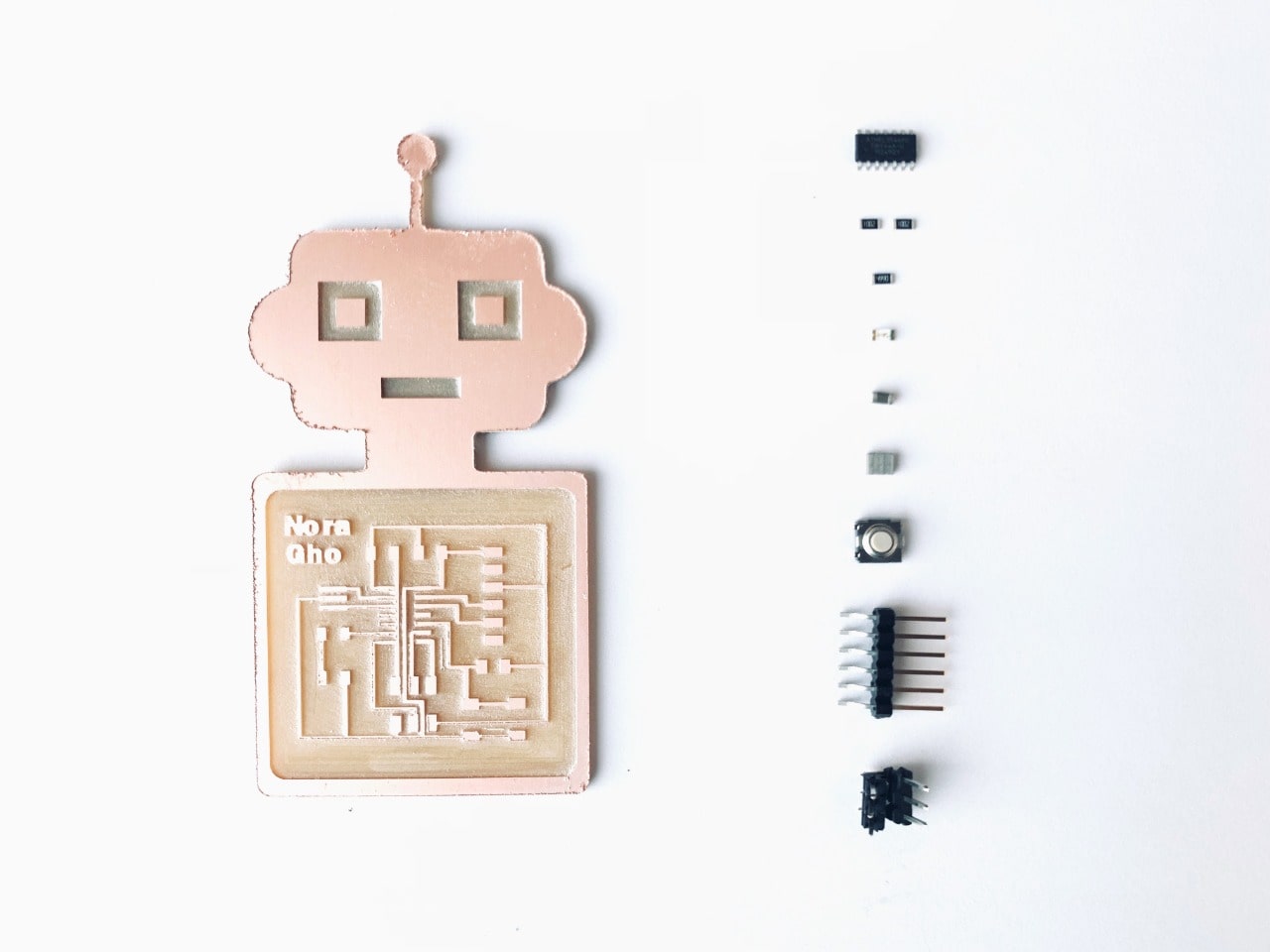
Wow, the final result ! A M A Z I N G !!
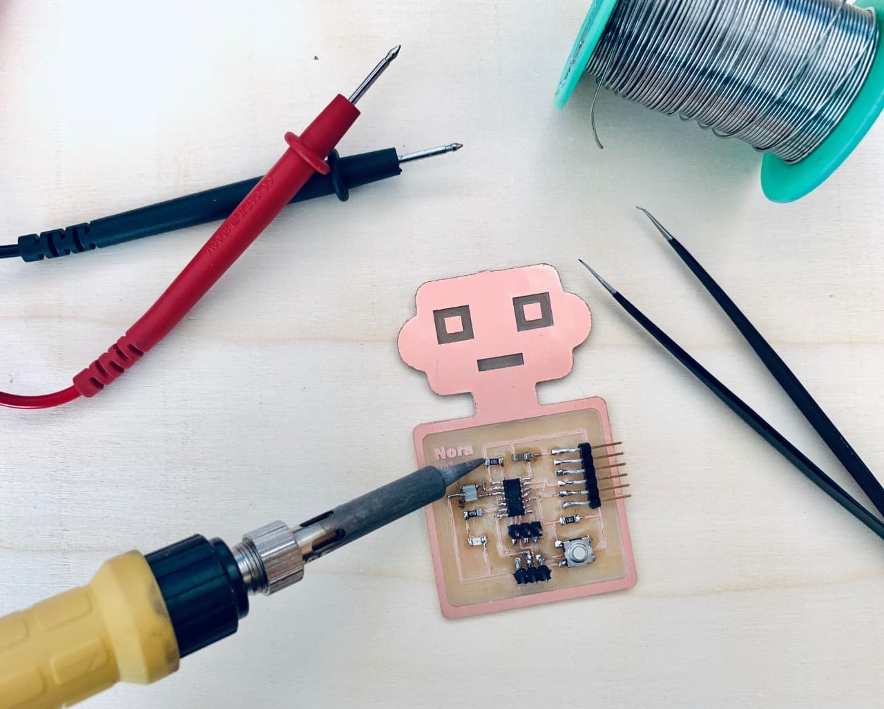
Soldering !
I collected the required componants and used the slodering to solder them.
Programing !
There are some steps I have to follow to upload the code to the microcontroller ATtiny44.
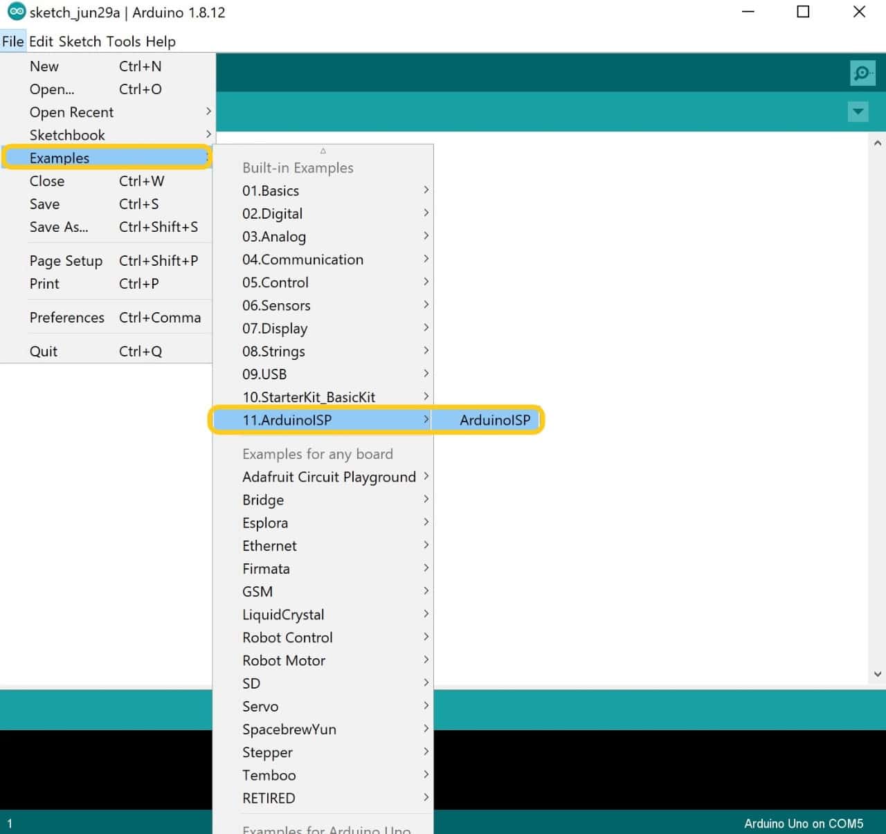
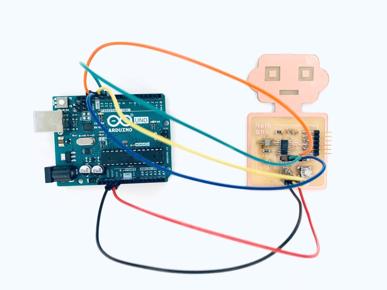
First, I connected the Arduino with the computer by using a USB cable then I opened File in Arduino IED and chose an Example then ArduinoISP this option will make the Arduino work as ISP to transfer the codes from the software to the microcontroller.
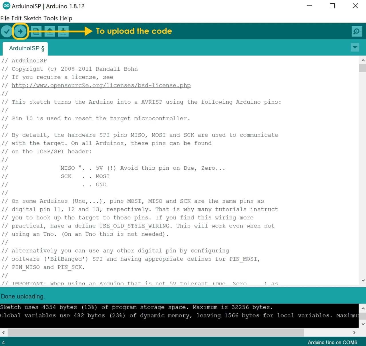
After that, I uploaded the ISP code.
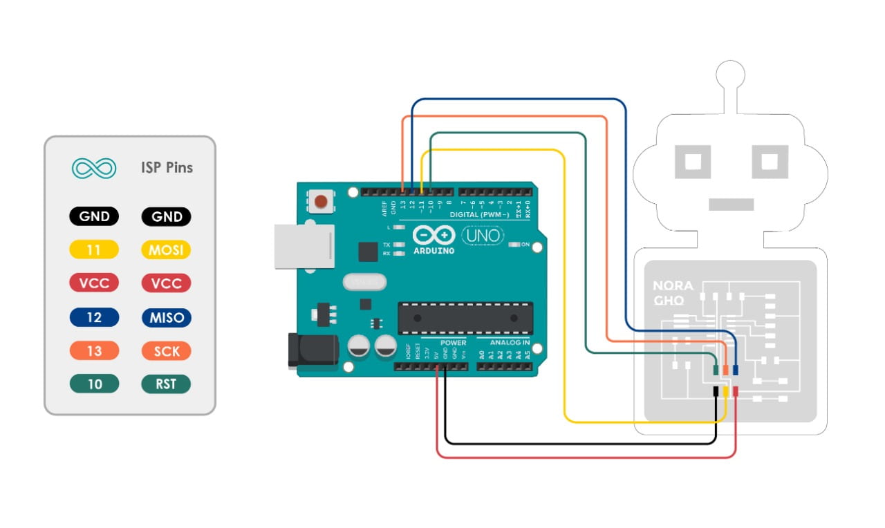
I Connected the PCB with the Arduino by using male to female jumper wires between the ISP pins in the board and the Arduino as shown below:
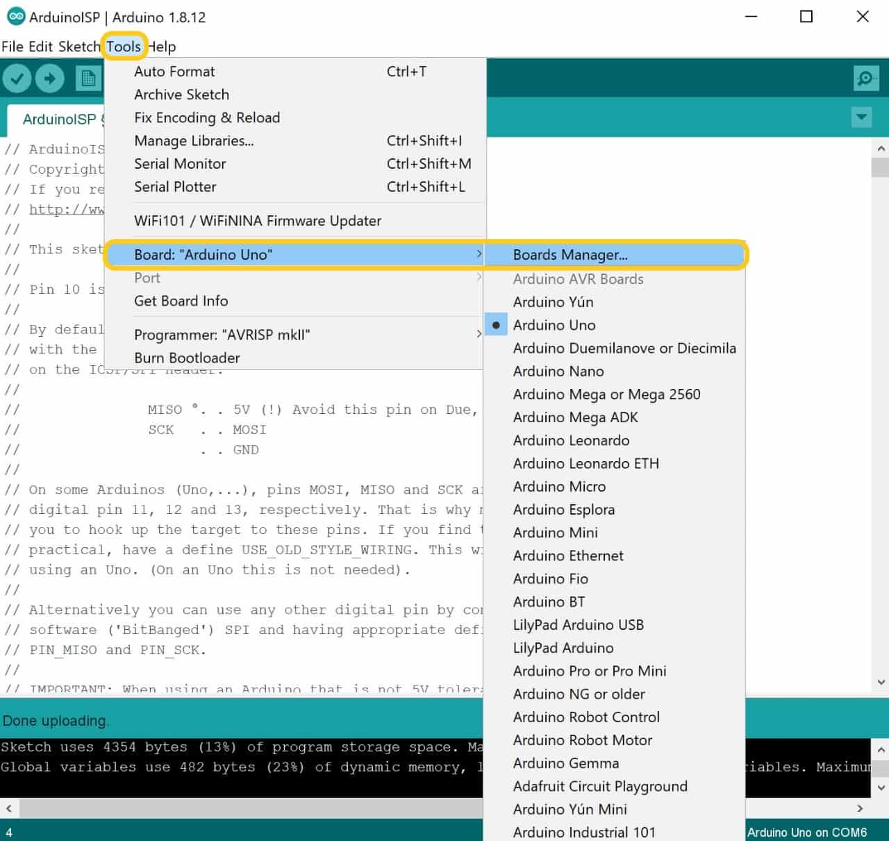
Before connecting the PCB to the computer, I have to check the Arduino IDE if it has ATtiny44 board or not by clicking on Tools then Boards. I searched for ATtiny44 in Board Manager but I did not find it. There are some steps I have to take to get ATtiny44 board.
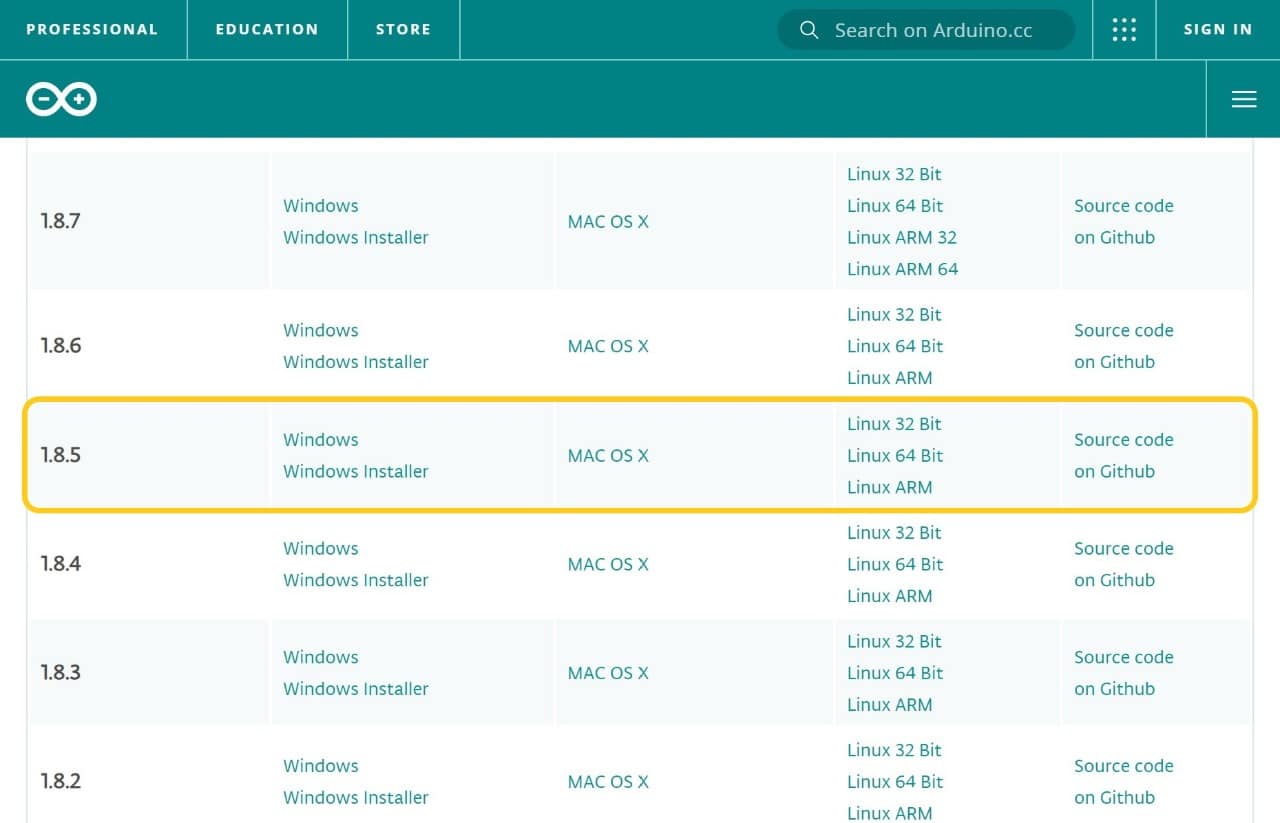
First, I uploaded the Arduino 1.8.5 version.
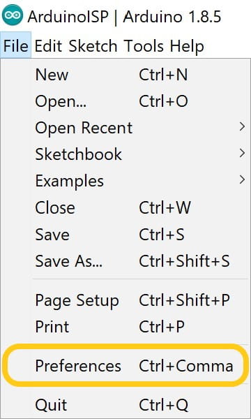
Then, I opened Arduino IDE software and clicked on file then preference.
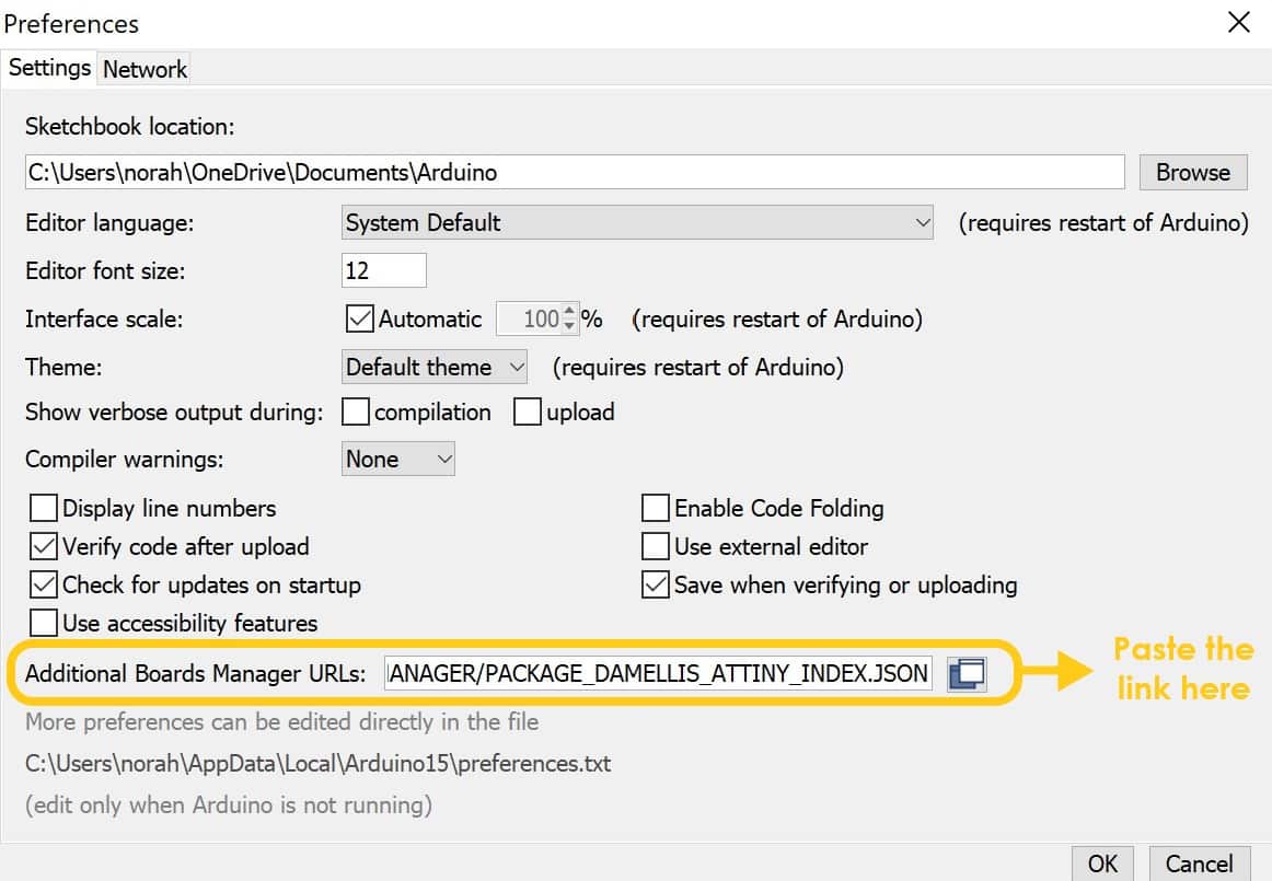
I copied the following link:
https://raw.githubusercontent.com/damellis/attiny/ide-1.6.x-boards-manager/package_damellis_attiny_index.jsonThen, I pasted the link to define the boards package.
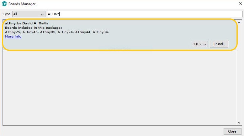
After that I closed the Arduino IDE and ran it again. I Go to Tools > Board > Board Manager once again and finally I found the ATtiny44 package and installed it.
Testing And Programming The PCB:
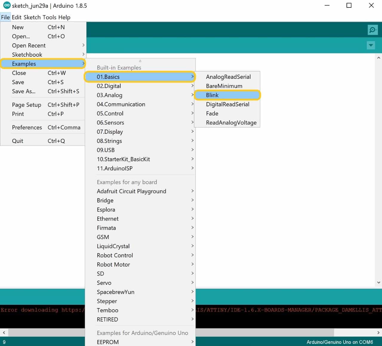
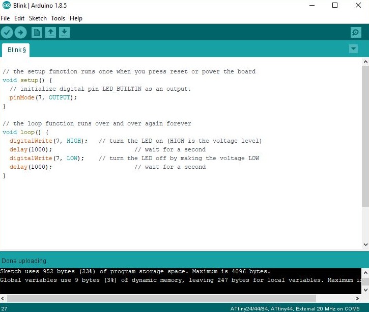
I tested the PCB by using blink code to get this code go to file > examples > basics and chose blink.
The Code:
The code will turn the LED on for one second, then off for one second, repeatedly.
Void Setup Section:
The setup function runs once when we press reset or power the board.
pinMode(7, OUTPUT);
Void Loop Section:
The loop function runs over and over again forever.
digitalWrite(7, HIGH);
delay(1000);
digitalWrite(7, LOW);
delay(1000);
Uploade The Code:
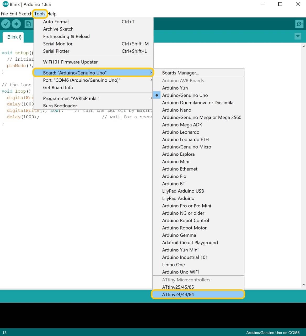
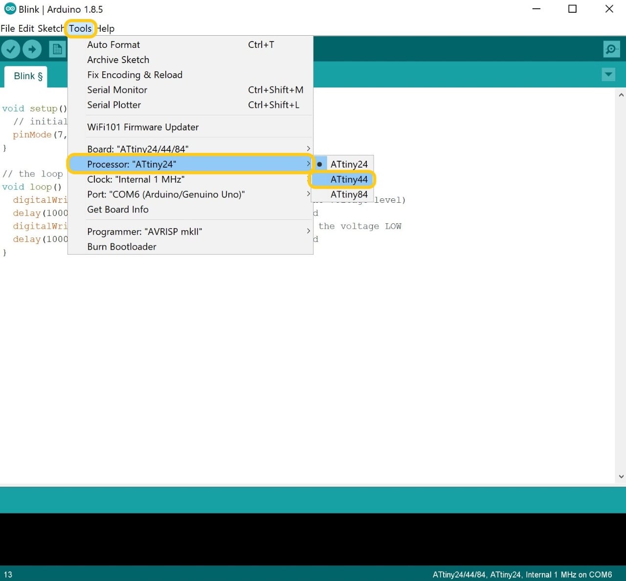
To uploaded the code I have to change some settings, I clicked on Tools and I chose the followings:
Go to Tools > Board > Attiny24/44/84.
Then, Tools > Processor > ATtiny44.
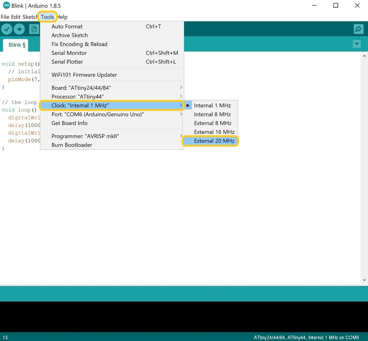
After that I chose Tools > Clock > External 20 MHz.
After connecting the USB cable go to Tools > Port > COM5 (Any port that is shown).
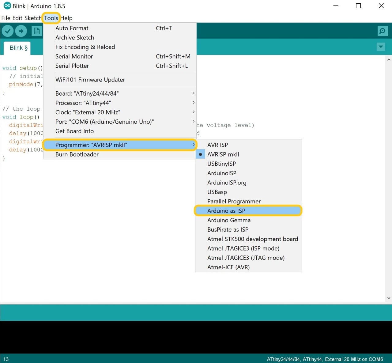
Then, Tools > Programmer > Arduino as ISP.
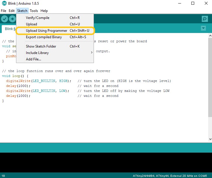
The last step is to start uploading the code through the Arduino to the PCB board. I clicked on the Sketch then I chose Upload Using Programmer.
The code has been uploaded successfully!
And finally It works perfectly!
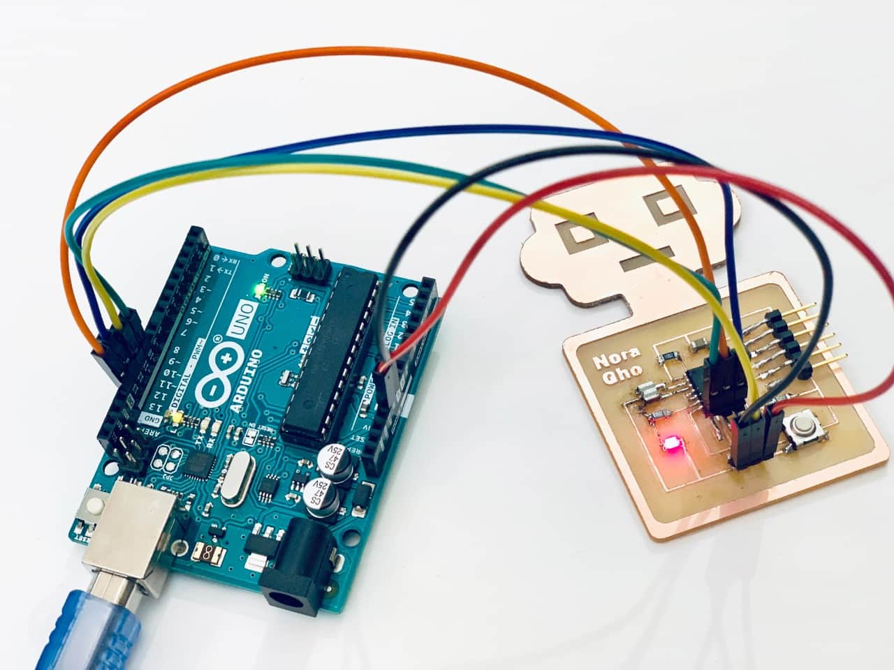
Done Done Done!