< /Input Devices >
This assignment is so fun ! We will use some input devices and measure the signals. I love learning new electronics components and connecting circuits. I feel that I’m so GENIUS Hahaha!! I hope to be an expert in the electronics field in the future !
Group Assignment
In the group assignment, we were asked to probe an input device's analog and digital signals.
You can check this link for more details about the group assignmnet: Input Devices - Group Assignment.
Individual Assignment
We will add input devices to the microcontroller board then test them. As I told earlier, we have coronavirus and our lab is closed. So, I’m going to use a little Arduino kit to test the input devices. In our kit we have some input devices and sensors such as :
In this assignment, I will use Tinkercad circuit to draw the circuits and make a simulation. Also, I’m going to use Arduino software to do the programming.
Tinkercad:

To open the website : Tinkercad Circuits
Arduino Software:

To download the software : Arduino
I’m going to use Arduino software to program the devices. I talked about this software in detail in the Embedded Program Assignment. I will write the steps once again because we will use them with all the devices while programming. After connecting the components we have to follow the steps:
1. Open the Arduino software > Paste/Write the code.
2. Connect the cable to the computer > Go to tools > Choose the port (COM5).
3. Click on Verify > Upload the code.
Now, let’s start the experience! So excited to learn about the input devices. Are you excited ? I hope so =)
What is an Input device ?
An input device is a hardware device that sends data and control signals to an information processor such as a computer and Arduino.
In this assignment, I chose to test two input devices:
After the lockdown period, we are finally back to the LAB. For this assignment and upcoming assignments I decided to design a new PCB by using Atmega328p microcontroller.
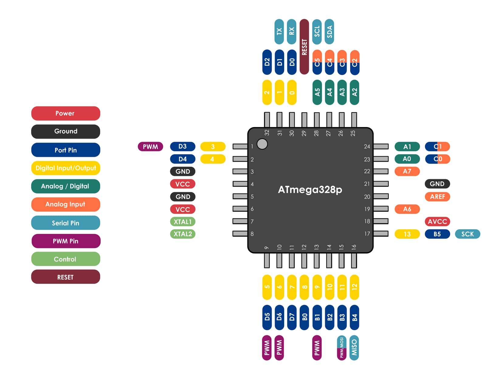
What is the ATmega328P Microcontroller?
ATMega328P Microcontroller is a high performance, low power controller from Microchip.
Atmega328p Diagram
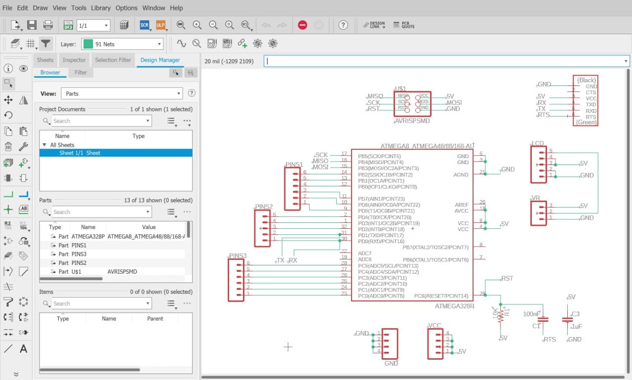
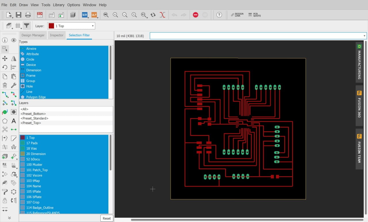
Design The PCB:
Now, I am going to use Eagle software to make the PCB design.
For more information about how to use Eagle software you can check Electronic Design Assignment.
The Electronic Components:
The 3 main components required with ATmega328P to allow us to upload the code are:
Headers for:
Schematic:
Board:
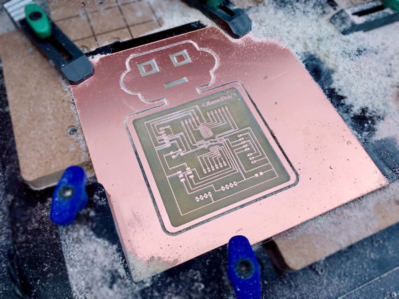
PCB Fabrication:
After finishing the design, I imported the file to Easel software and I used the Carvey milling machine to mill the PCB.
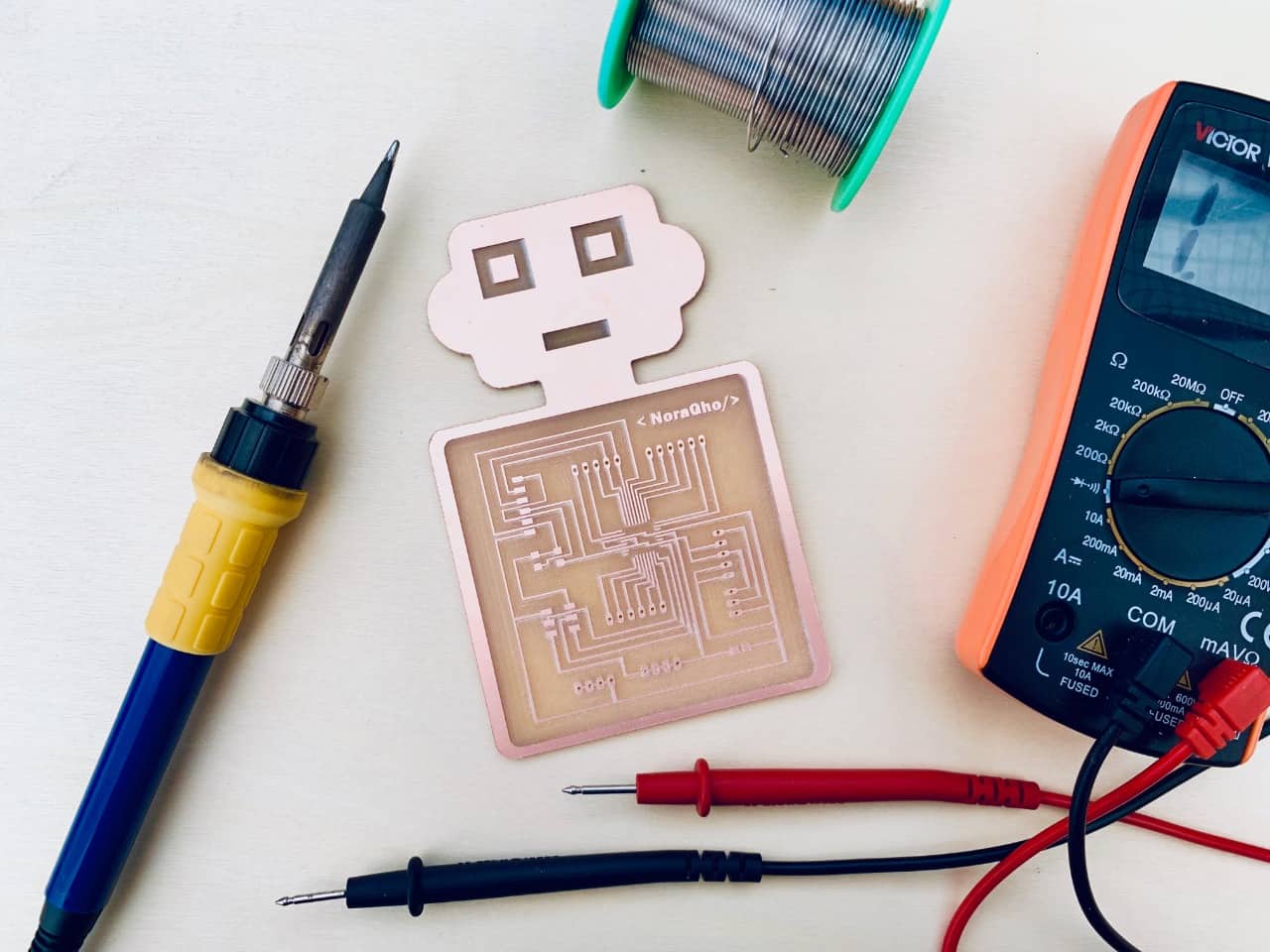
This is the final result! It is time to solder the components.
PCB Soldering:
After milling out the trace and cutting out the board we are ready to stuff the board.
PCB Testing :
To program this microcontroller, there are some steps I have to follow:
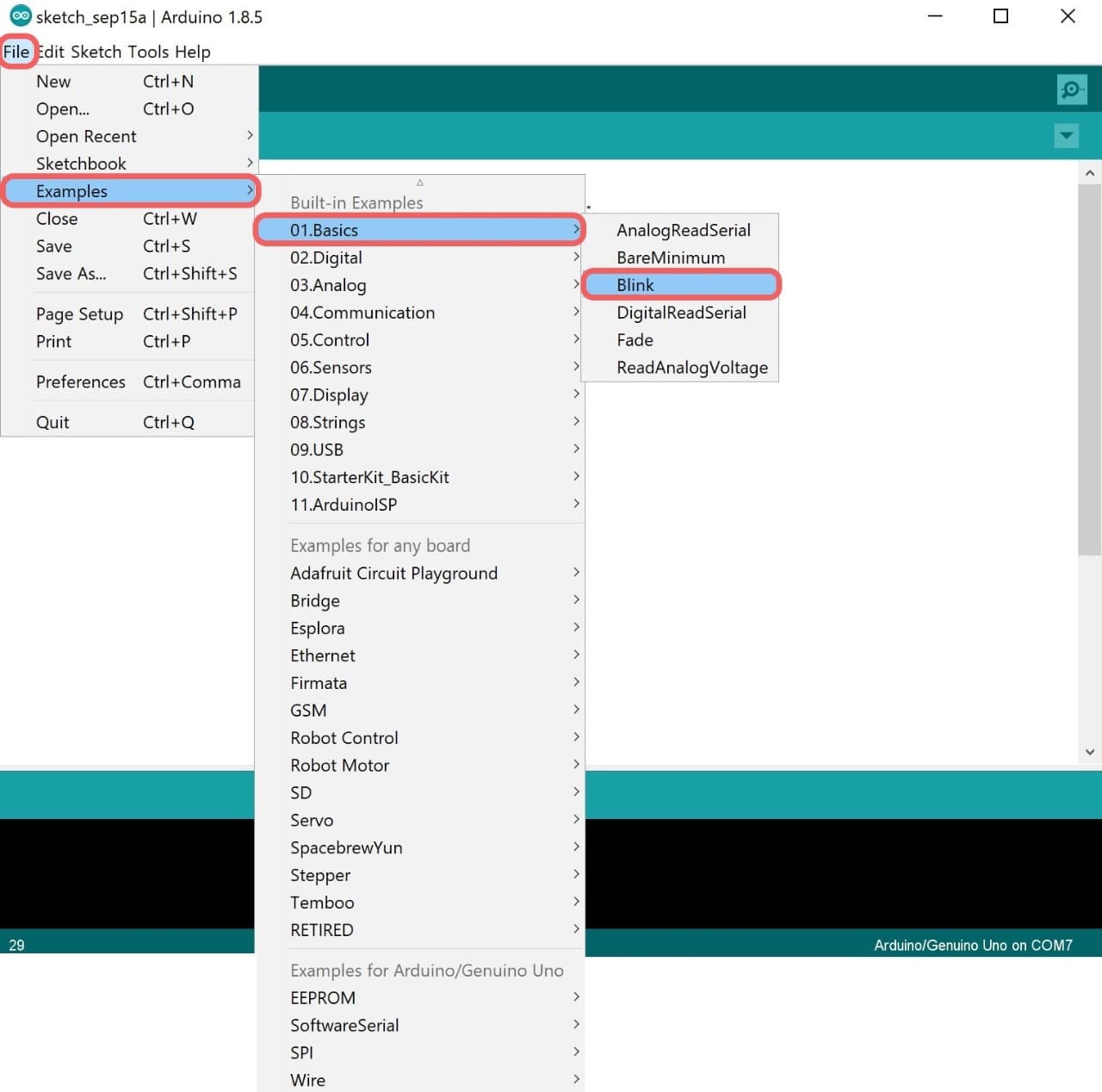
First, I connected the Arduino with the computer by using a USB cable. Then, I opened Arduino IED and chose :
File > Example > ArduinoISP > Arduino ISP.
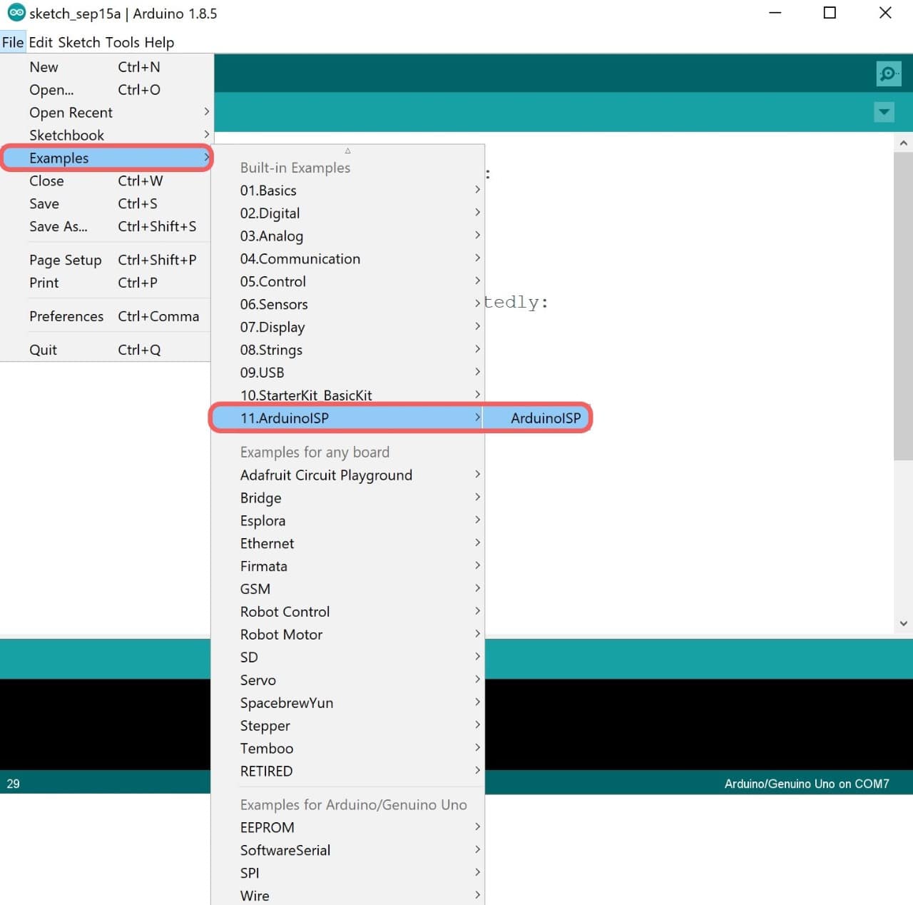
This option will make the Arduino work as Programmer to transfer the codes from the software to the microcontroller.
After that I uploaded the ISP code.
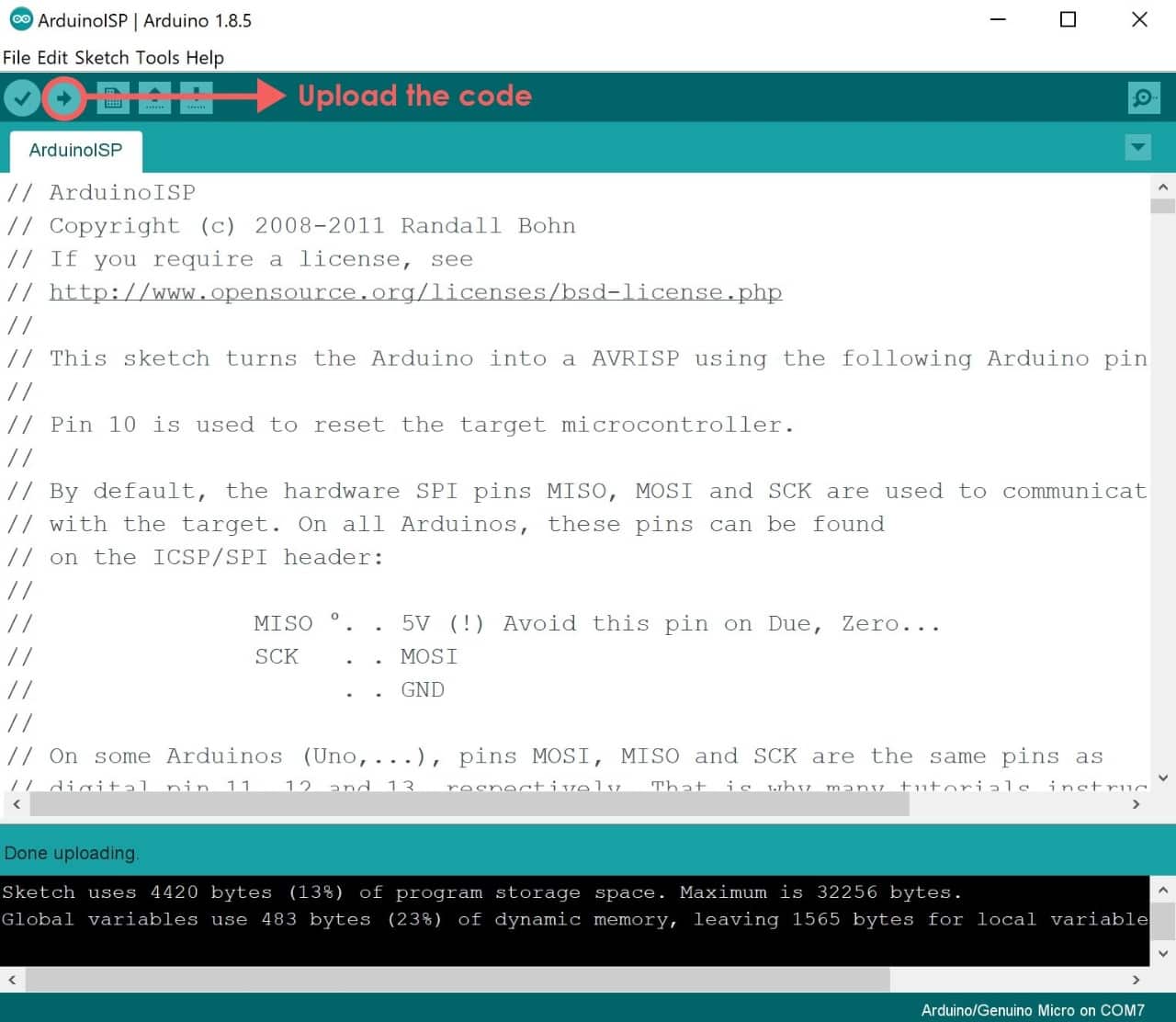
I Connected the PCB with the Arduino by using male to female jumper wires between the ISP pins in the board and the Arduino as shown below:
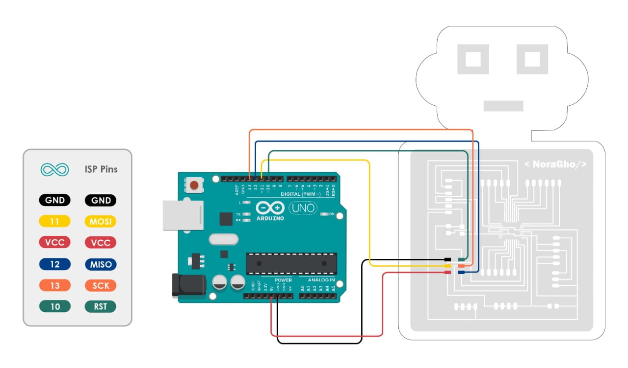
As I said before, I am going to use an Atmega328p microcontroller. So, I read the datasheet to know how to connect the wires. I connected the wires by following the diagram of Atmega328p microcontroller that shown above.
I am going to test the PCB by using simple blinking code to ckeck if it works or not.
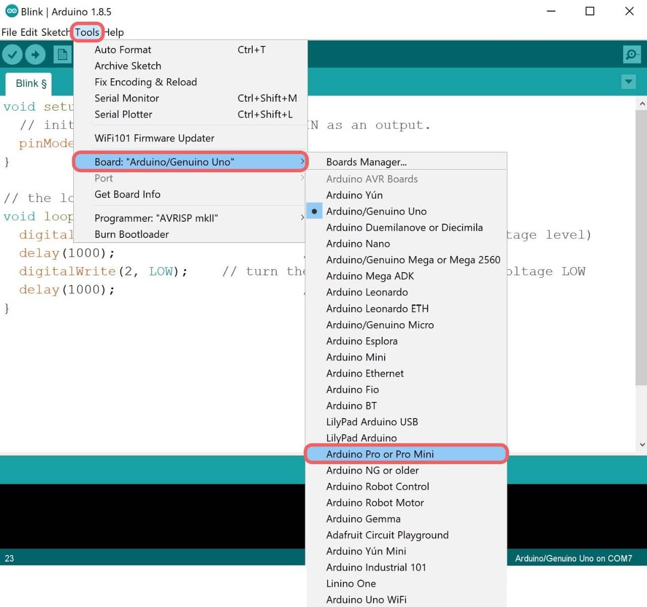
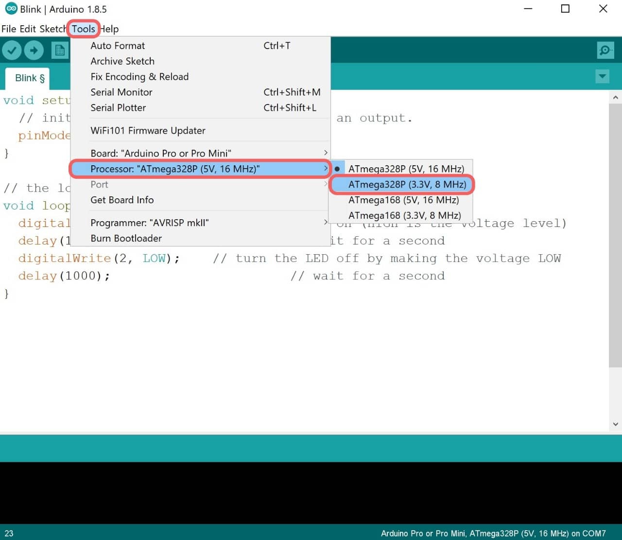
To upload the code I have to change some settings, I clicked on Tools and I chose the followings:
Go to Tools > Board > Arduino Pro or Pro Mini.
Then, Tools > Processor > Atmega328P (3.3 V, 8 MHz).
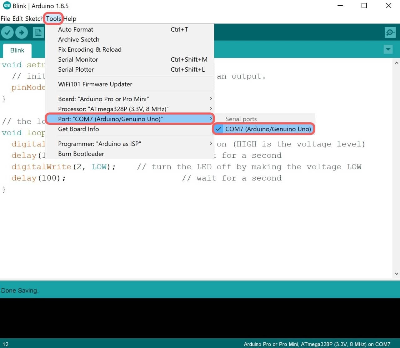
After connecting the USB to the computer go to Tools > Port > COM7 (Any port that is shown).
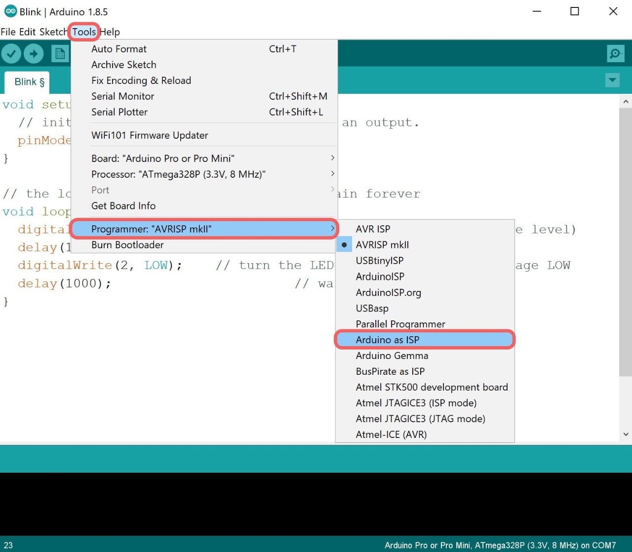
Then, Tools > Programmer > Arduino as ISP.
The last step is to start uploading the code through the Arduino to the PCB board. I clicked on the Sketch then I chose Upload Using Programmer.
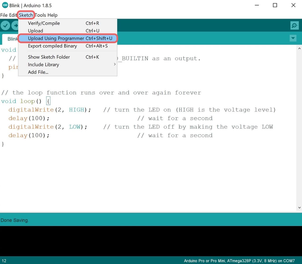
The code has been uploaded sucsessfully!
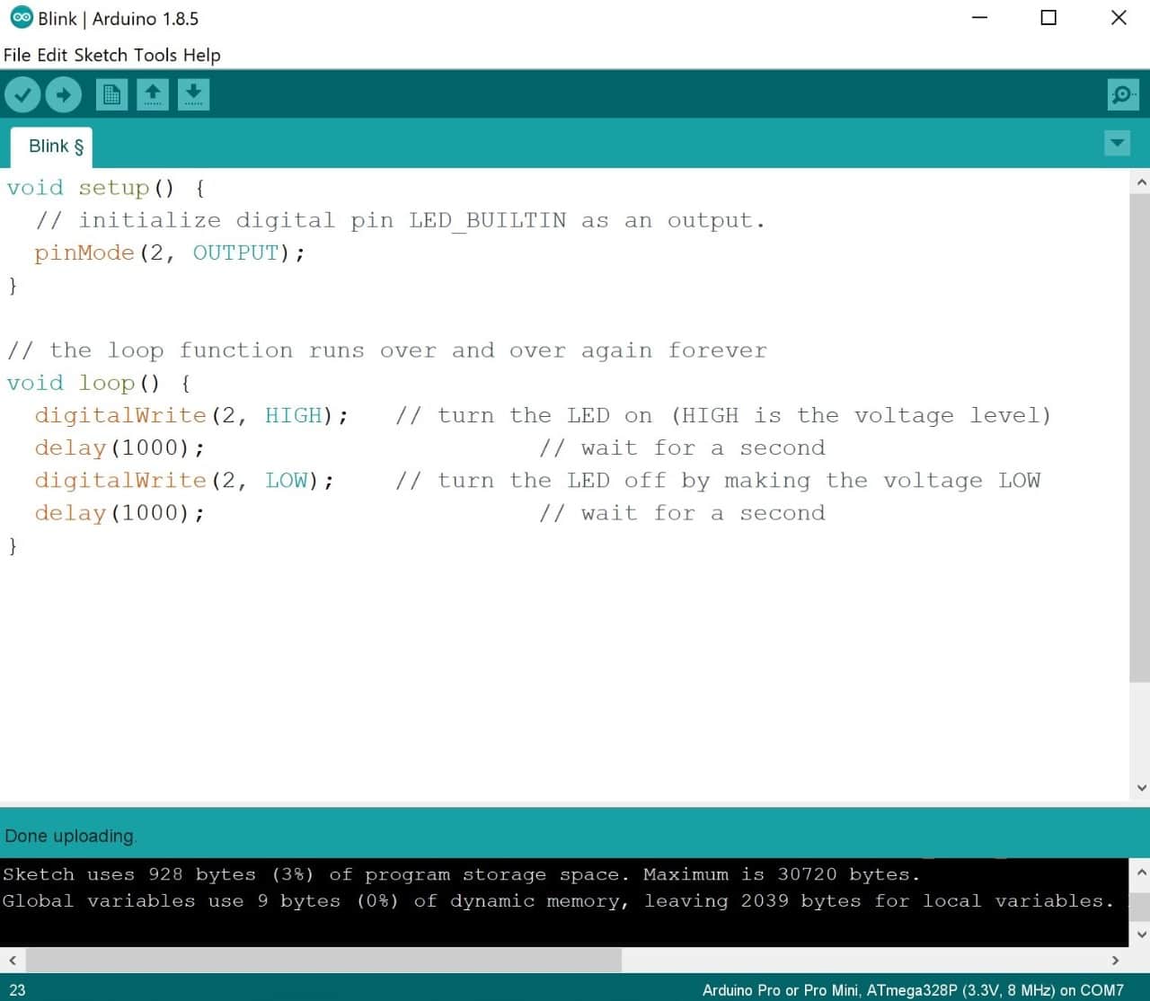
It works!
Now, I am going to do some projects by using input devices. All the projects will contain two tests one with Arduino which I did during the lockdown and the other test by using the PCB.
Ultrasonic Sensor
What is an Ultrasonic sensor ?
An ultrasonic sensor is an input electronic device that measures the distance of a target object by emitting ultrasonic sound waves, and converts the reflected sound into an electrical signal.
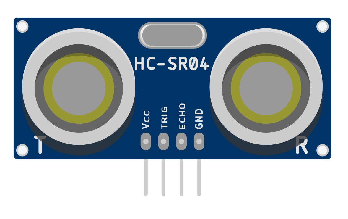
Ultrasonic Parts:
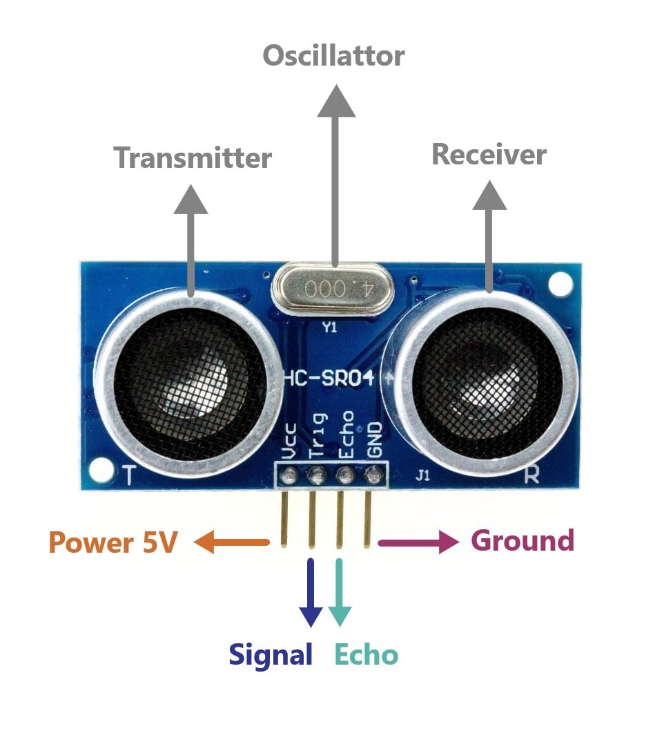
There are two main parts in the ultrasonic sensor:
It has 4 pins:
How does an Ultrasonic sensor work ?
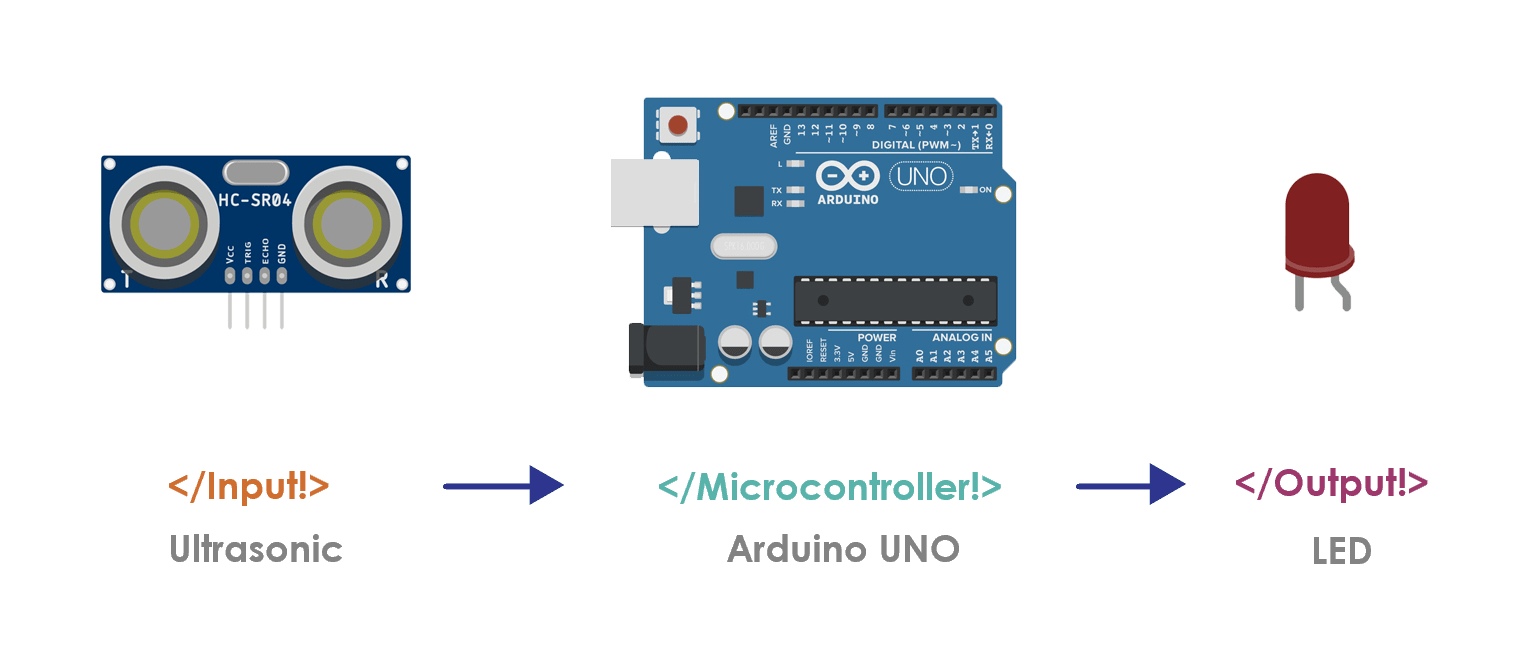
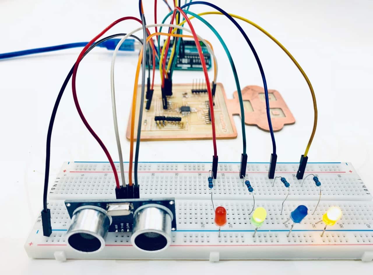
Let’s Make it !
First, I will test the ultrasonic only then I’m going to make a small project by using ultrasonic and LEDs.
Components:
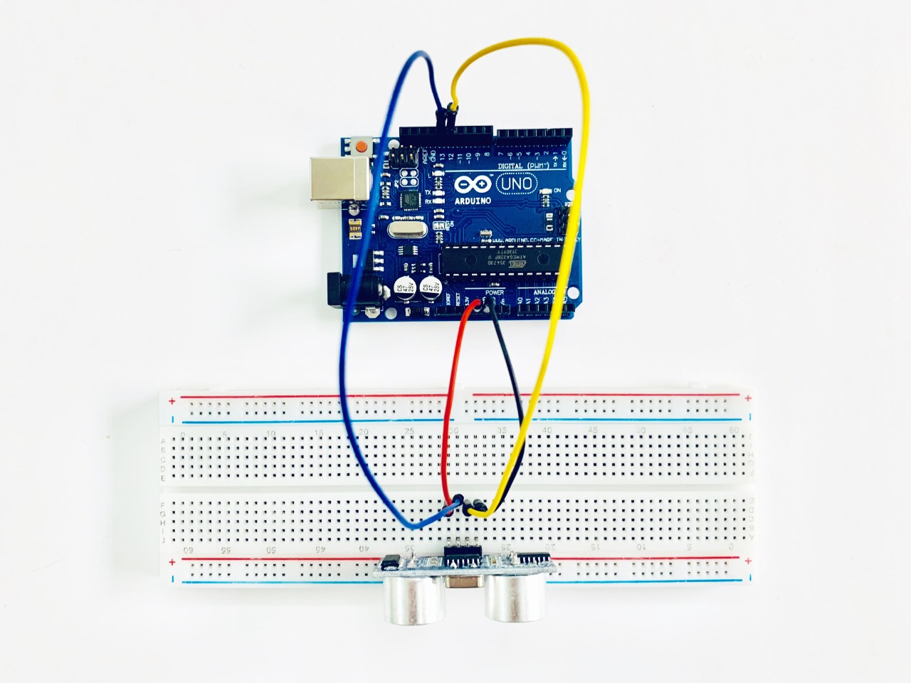
Let’s connect the components !
The circuit
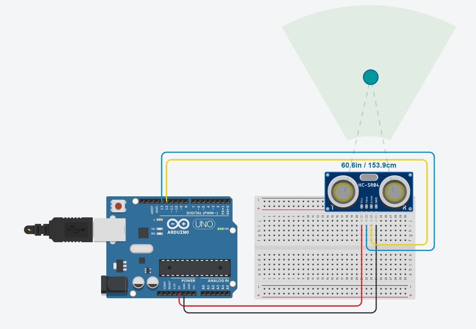
Let’s Program !
The code
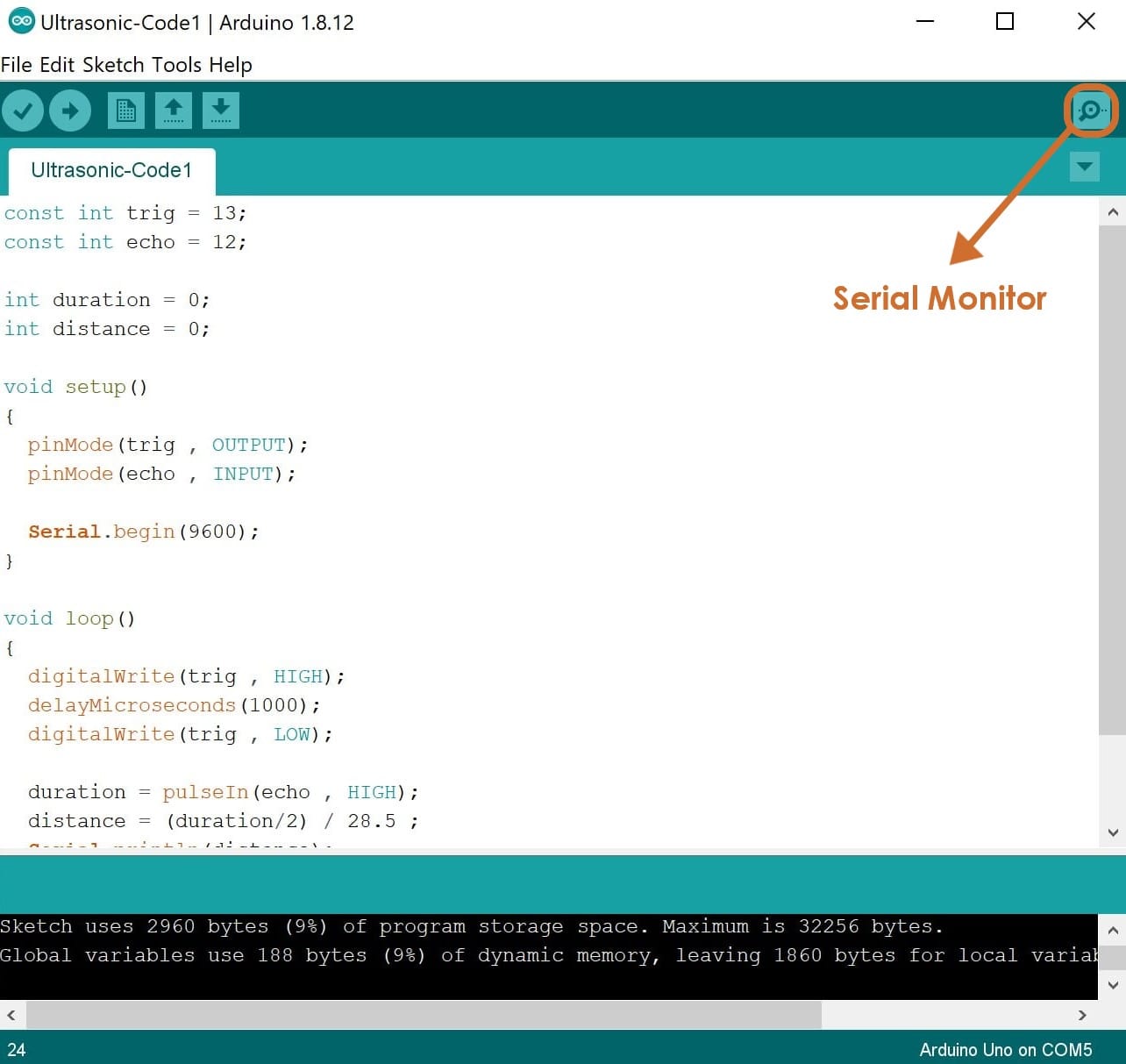
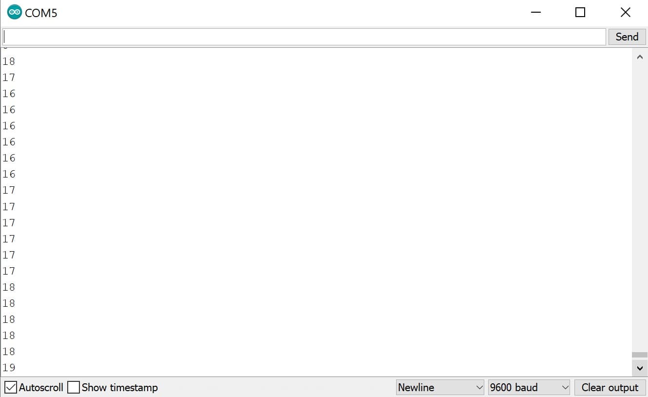
Wahooo It’s Working ! To see the distance > Go to tools > Serial monitor.
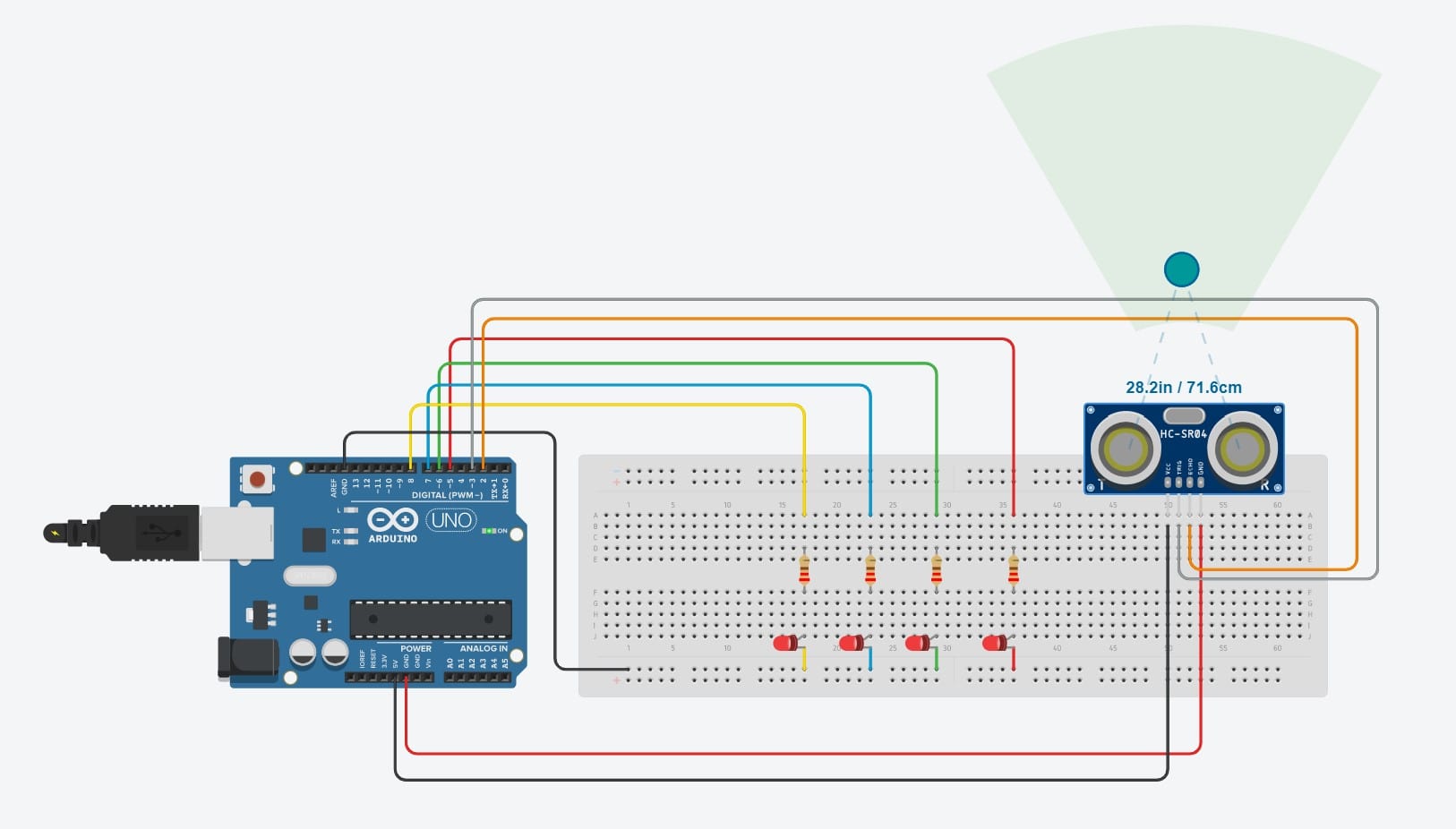
I decided to add 4 LEDs to measure the distance of the object. When an object comes close the ultrasonic sensor indicates the distance using led.
Components:
Let’s connect the components:
The circuit
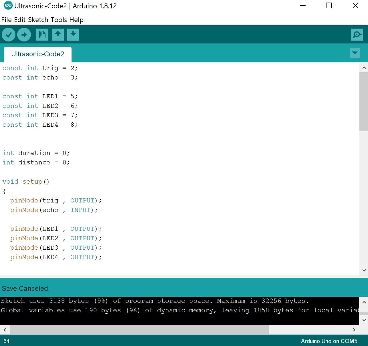
Let’s Program !
The code
const int trig = 2;
const int echo = 3;
const int LED1 = 5;
const int LED2 = 6;
const int LED3 = 7;
const int LED4 = 8;
int duration = 0;
int distance = 0;
Void Setup Section :
  pinMode(trig , OUTPUT);
  pinMode(echo , INPUT);

  pinMode(LED1 , OUTPUT);
  pinMode(LED2 , OUTPUT);
  pinMode(LED3 , OUTPUT);
  pinMode(LED4 , OUTPUT);
Serial.begin(9600);
Void Loop Section :
digitalWrite(trig , HIGH);
delayMicroseconds(1000);
digitalWrite(trig , LOW);
duration = pulseIn(echo , HIGH);
distance = (duration/2) / 28.5 ;
Serial.println(distance);
If the distance is less than or equal 7 cm, the RED LED will turn on.
if ( distance <= 7 ){
digitalWrite(LED1, HIGH);
Else, the RED LED will turn off.
else{
digitalWrite(LED1, LOW);
If the distance is less than or equal 14 cm, the GREEN LED will turn on.
if ( distance <= 14 ){
digitalWrite(LED2, HIGH);
Else, the GREEN LED will turn off.
else {
digitalWrite(LED2, LOW);
If the distance is less than or equal 21 cm, the BLUE LED will turn on.
 if ( distance <= 21 ){
digitalWrite(LED3, HIGH);
Else, the BLUE LED will turn off.
else{
digitalWrite(LED3, LOW);
If the distance is less than or equal 21 cm, the YELLOW LED will turn on.
if ( distance <= 28 ){
digitalWrite(LED4, HIGH);
Else, the BLUE LED will turn off.
else{
digitalWrite(LED4, LOW);

Now, Enjoy testing the distance!
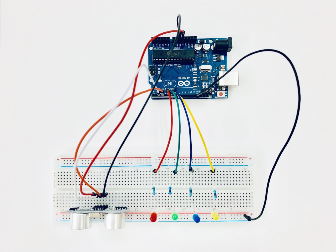
Arduino Testing and Programming :
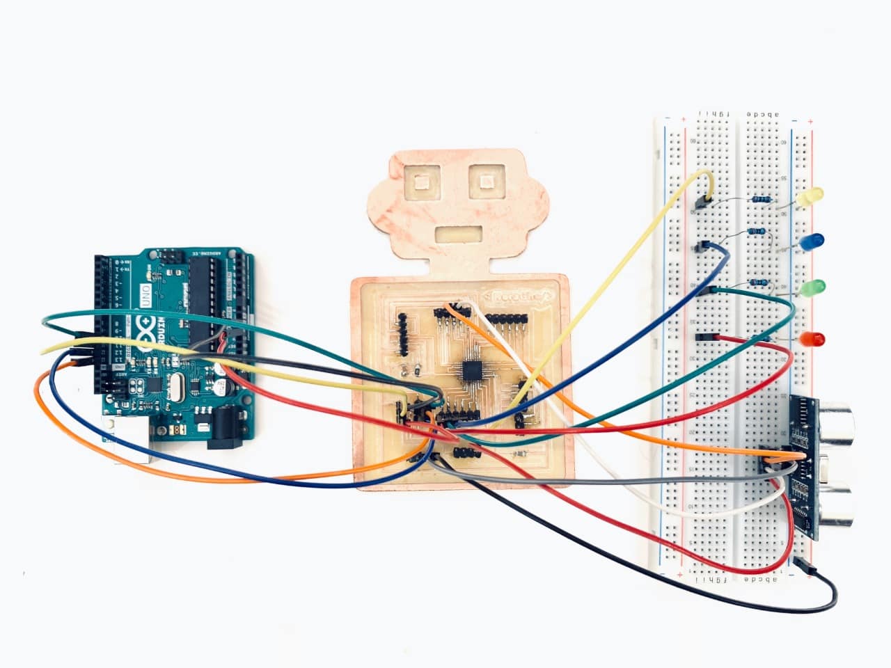
PCB Testing and Programming :
I am going to make another project by using LDR sensor.
LDR Sensor
What is LDR sensor?
LDR (Light Dependent Resistor) is an input component that has a variable resistance that changes with the light intensity.
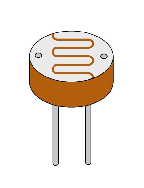
LDR Parts:
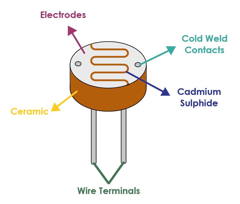
How does LDR work ?
When light increases then the LDR resistor decreases. And when light decreases then the LDR resistor increases. LDR stands for Light dependent resistor.
Application in our life:
It’s generally used in applications when light is an important factor to the device it’s being used. For example, street lights. Street lights need to know when it’s light dark outside so that they know when to turn on or turn off.
Let’s Make it !
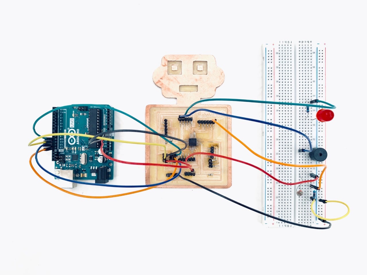
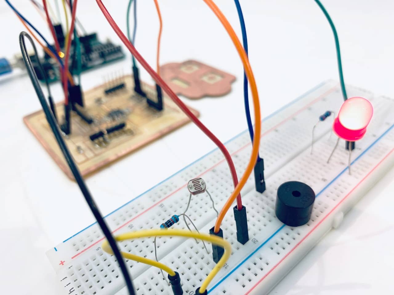
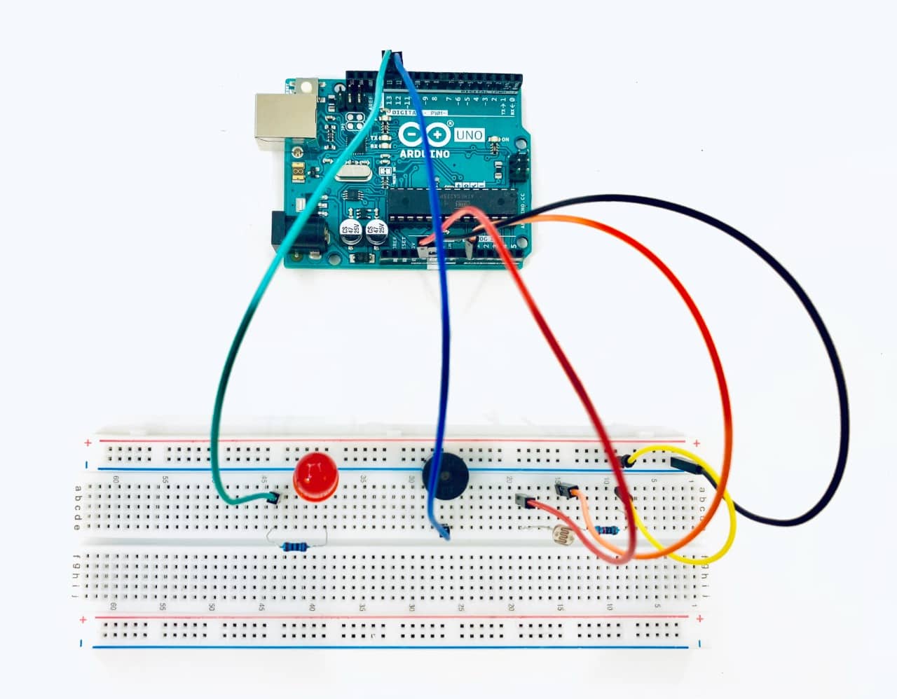
In this project, I'm going to use LDR as an input and LED and buzzer as an output. When the light shines, LDR will activate a buzzer and LED. The buzzer will give an alarm and the LED will flash. And when the light is decreased, the LED and buzzer will immediately turn off.
The components :
Let’s connect the components !
The Circuit
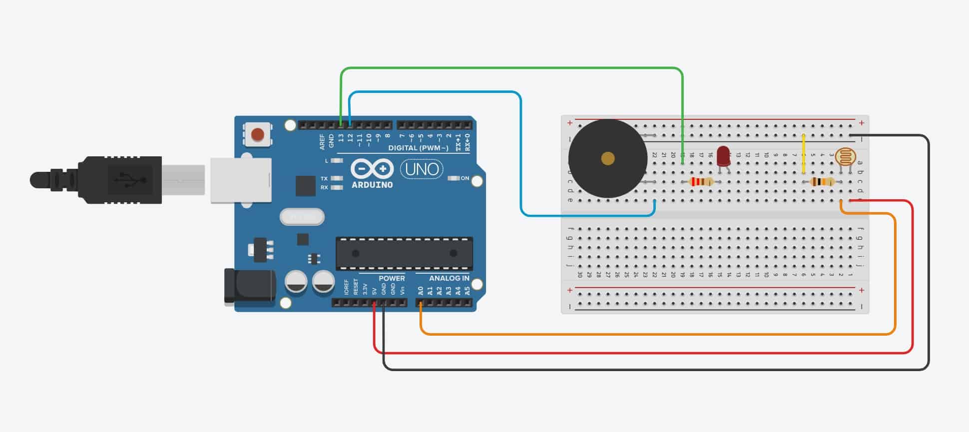
Arduino Connection:
The Code :
const int ledPin = 13;
const int buzzerPin = 12;
const int ldrPin = A0;
Void Setup Section :
Serial.begin(9600);
pinMode(ledPin, OUTPUT);
pinMode(buzzerPin, OUTPUT);
pinMode(ldrPin, INPUT);
Void Loop Section :
int ldrStatus = analogRead(ldrPin);
if (ldrStatus >= 400) {
tone(buzzerPin, 100);
digitalWrite(ledPin, HIGH);
delay(100);
noTone(buzzerPin);
digitalWrite(ledPin, LOW);
delay(100);
Serial.println("----------- ALARM ACTIVATED -----------");
else {
noTone(buzzerPin);
digitalWrite(ledPin, LOW);
Serial.println("ALARM DEACTIVATED");
Arduino Testing and Programming :
PCB Testing and Programming :