Here we go..
Output Devices !!
The goal of this week is to learn about output devices and make some applications. The difference between input and output devices are:
Input Device
Output Device
Group Assignment
In this assignment we were asked to measure the power consumption of an output device.
You can check the group assignment from this link : Group Assignment.
Individual Assignment
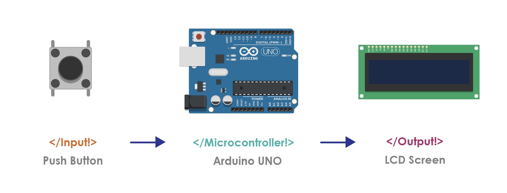
We are supposed to add an output device to a microcontroller board that we have designed, and program it to do something. As I said in the input device assignment, I’m going to use an arduino to test the devices.
Let’s talk more about output devices!
What is an output device ?
An Output device is a device that receives data (signal) from a computer/Arduino for display, projection, or physical reproduction.
Output devices examples:
In this assignment, I’m going to use:
LCD - Liquid Crystal Display
What is LCD display ?
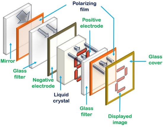
LCD is an output electronic display module which uses liquid crystal to produce a visible image.
16×2 LCD Specifications:
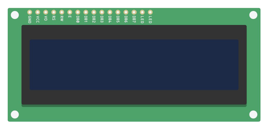
LCD display parts:
The LCD has 16 connection pins, numbered 1-16 from left to right.
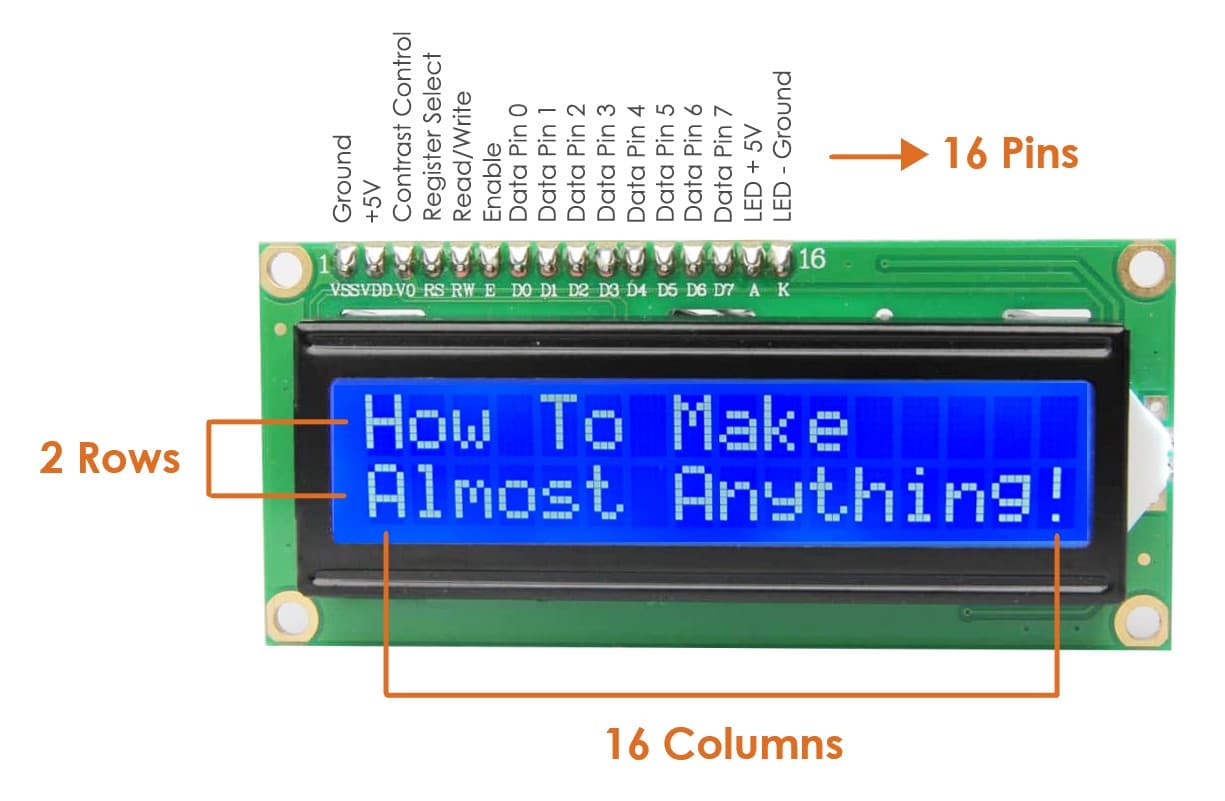
16×2 LCD pinout:
How does LCD display work ?
Let’s Make it !
I’m going to write some words by using LCD.
The Components:
What is a potentiometer ?
A potentiometer is a variable resistor used to adjust the contrast level of the LCD screen.
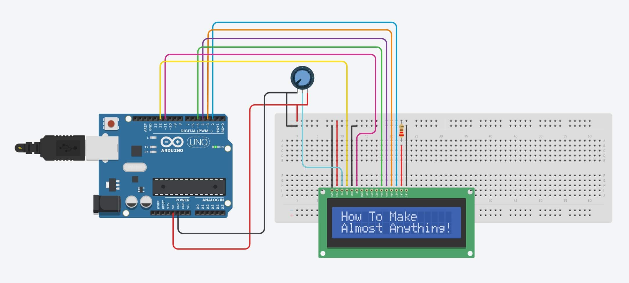
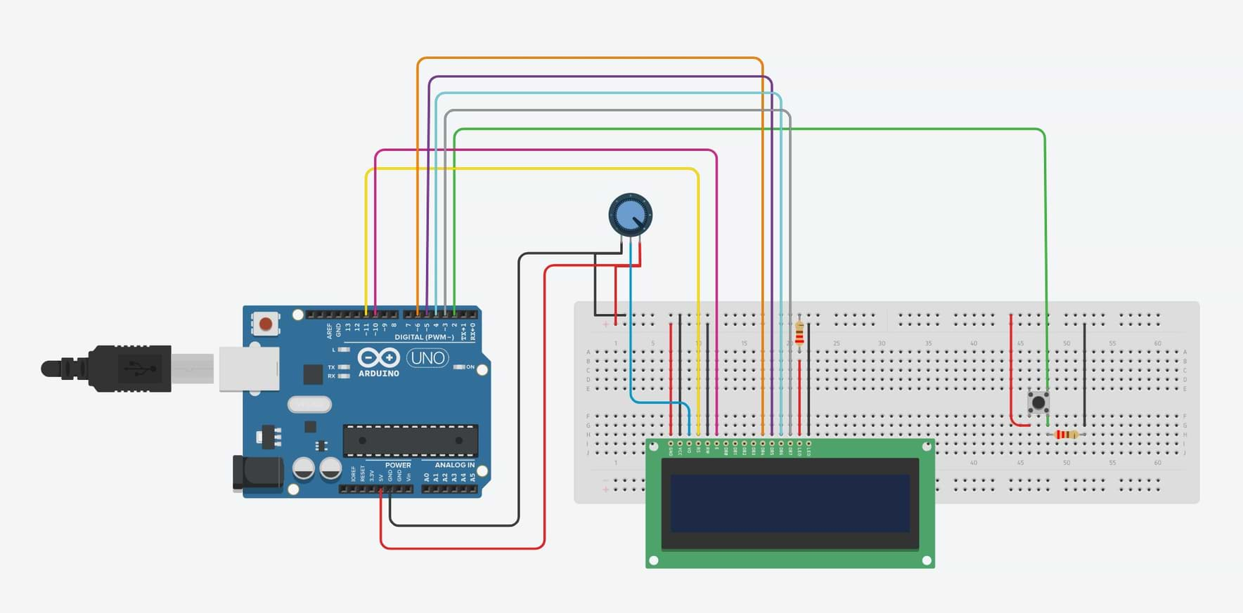
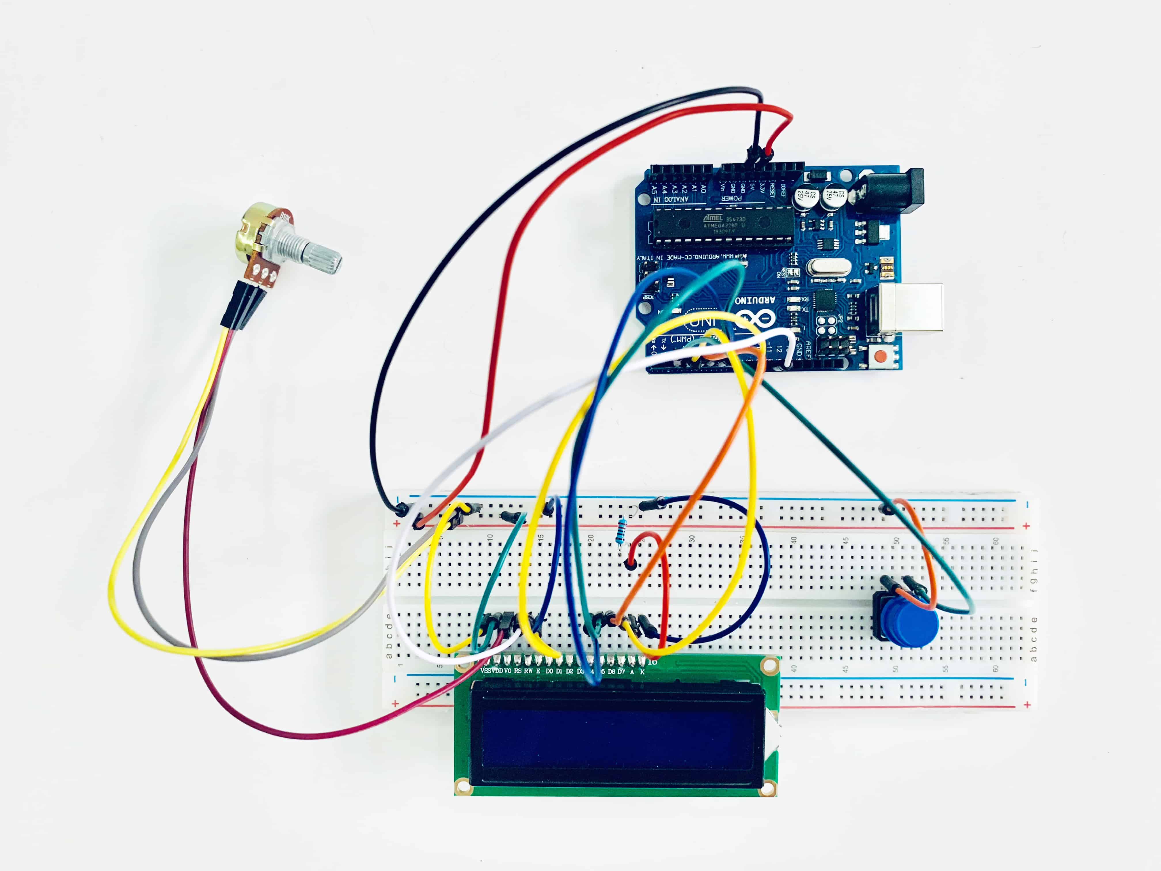
Let’s Connect the components !
The Circuit
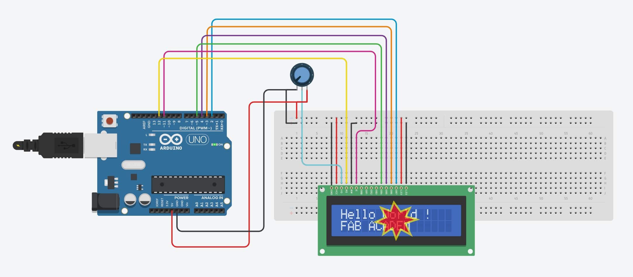
Ops! Ops ! I faced this issue while using a tinkercad to simulate the LCD. The problem is LCD backlight was 23.7 kA while maximum 20 mA. To fix this issue I added a resistor 220 Ohm then it works !
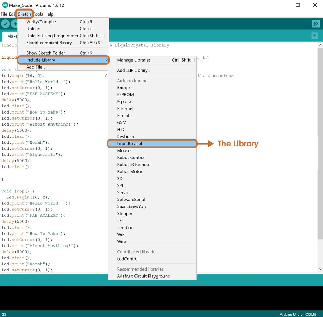
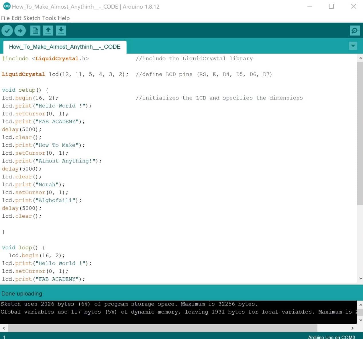
Let’s Program !
1. lets
I faced some problems after uploading the code. The code has been done but the LCD is not working!!
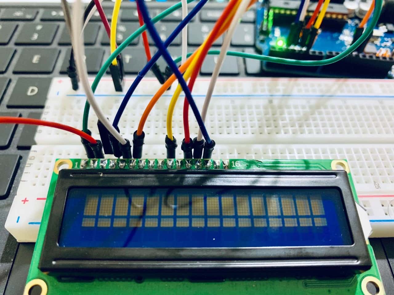
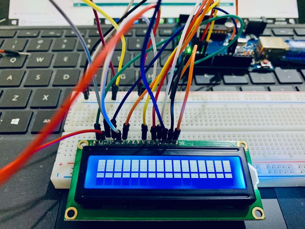
I rechecked the connection and the code to figure out the problem. YES I FOUND IT !
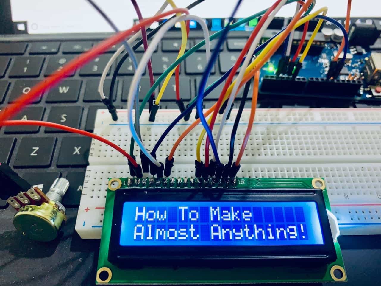
NOW IT IS WORKING !!!!
Potentiometer Test
LCD Display Arduino Test
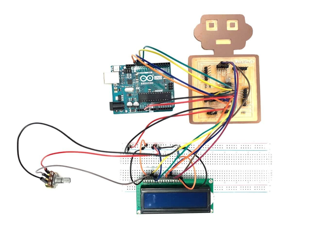
LCD Display PCB Test
I LOVE LCD DISPLAY !!!! So, I wanna make another application.
More Practice !
When I searched about LCD display applications I found that I can make different types of gaming in this amazing output device. I love gaming! It’s so fun to make a Jumping Jack game by using the following components:
Let’s Connect the components !
The circuit
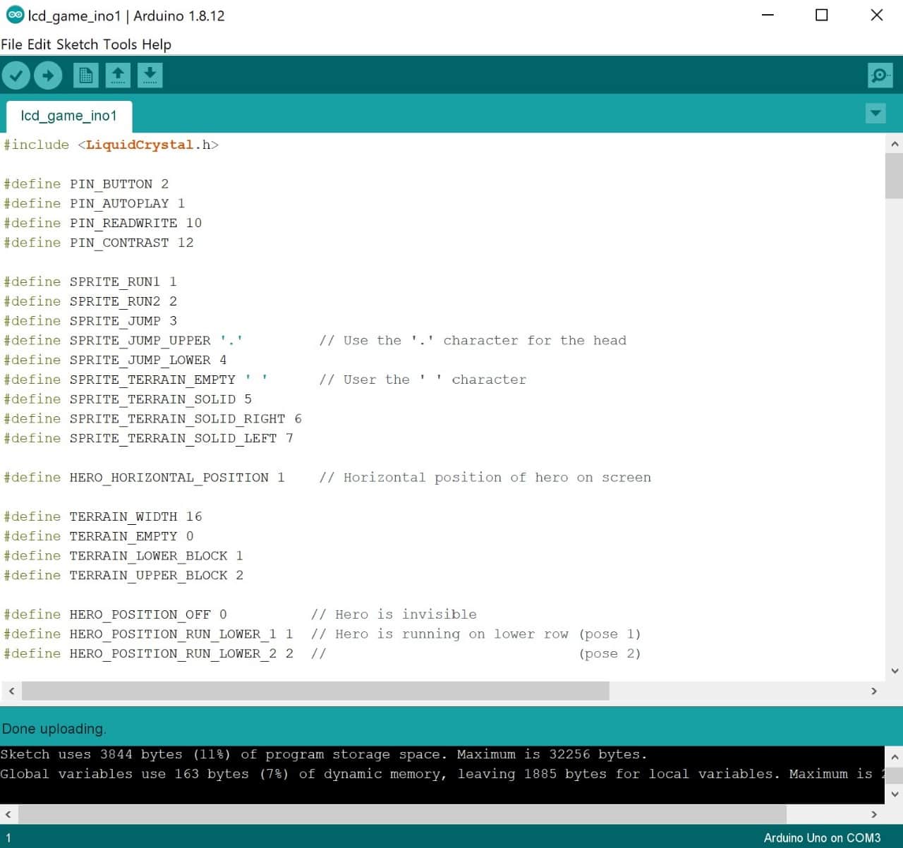
Let’s Program !
The Code
The Video
Whoooooo It’s Working! LET’S PLAY !!
Servo Motor
The second output device that I’m going to test is a servo motor.
What is Servo Motor ?
A servo motor is an electrical output device which can push or rotate an object with different directions/angles.
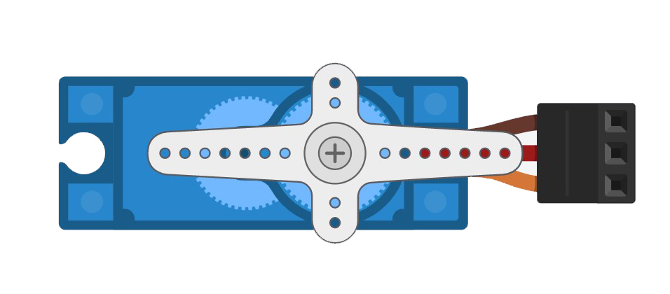
Servo Motor Parts:
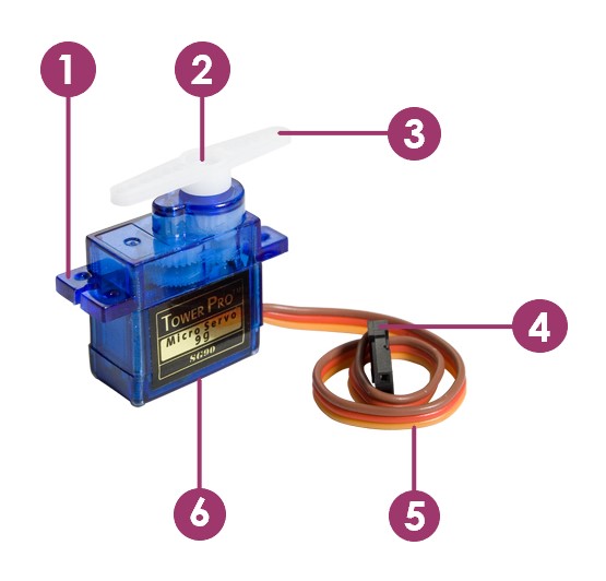
Outside
1. Mounting tabs.
2. Output shaft.
3. Servo horn.
4. Connector.
5. Cable.
6. Connector.
Inside
1. Motor.
2. Gearbox.
3. Position sensor.
4. Motor control electronics.
How does servo motor work ?
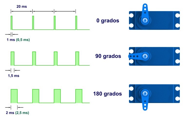
Servos are controlled by sending them a pulse of variable width. The control wire is used to send this pulse.
Applications in our life :
There are many aplications in our life using servo motor such as :
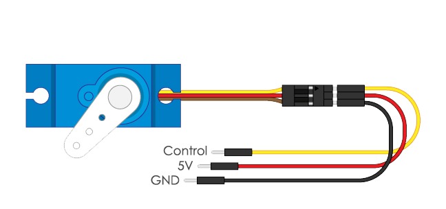
Servo Pinout:
Let’s Make it !
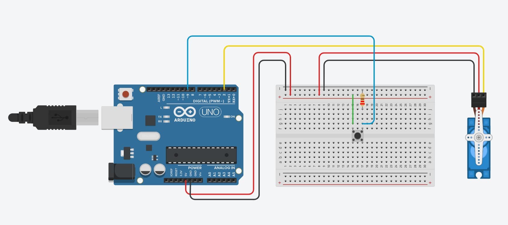
I’m going to control the servo motor by using push button.
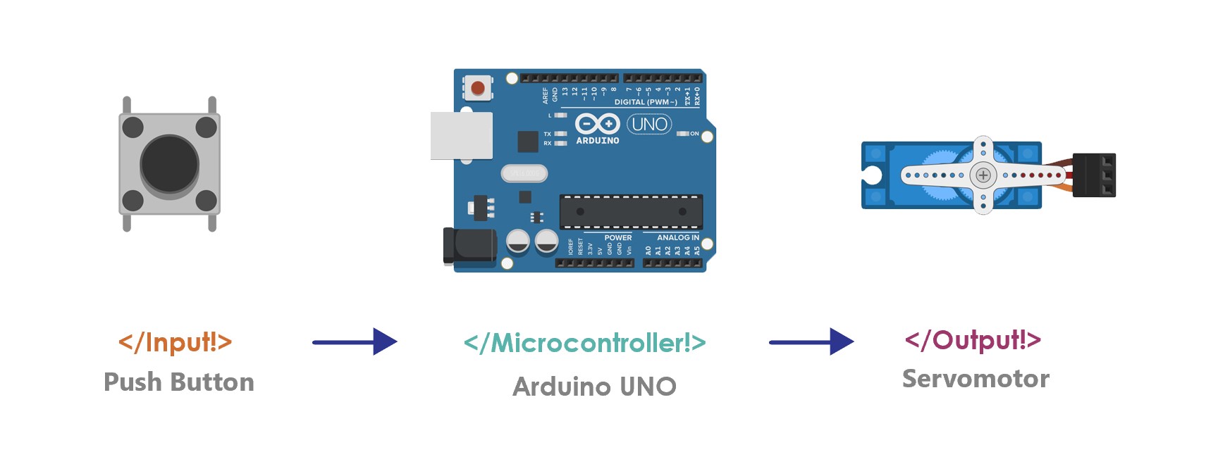
The components :
Let's connect the componants!

Let’s program !
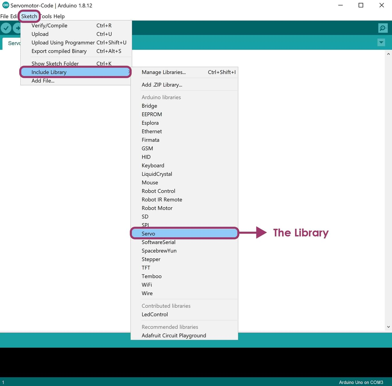
Now, I open Arduino IDE to upload the code. The bellow code will work as follow:1. I used the (h.servo) library by going to Sketch > Include Library > Servo.
#include Servo.h
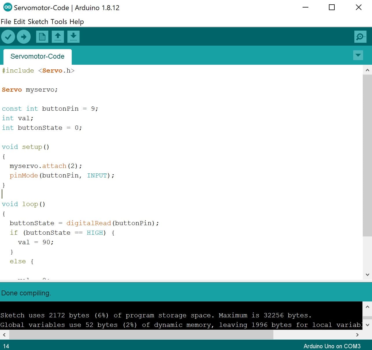
2. After connecting the wires, I dintified the pin ( ButtonPin = 9 ), ( Val means the value of the direction ).
const int buttonPin = 9;
int val;
int buttonState = 0;
3. In the void setup, I dintified the control pin of the servo (wired up to pin 2 in Arduino) and the pinMode of the push button as INPUT.
void setup()
{
  myservo.attach(2);
  pinMode(buttonPin, INPUT);
}
4. In the void loop, I idintified the value of the servo direction as (val=180). If I press on the push button the servo motor will rotate 180 degree.
void loop()
{
  buttonState = digitalRead(buttonPin);
  if (buttonState == HIGH) {
    val = 180;
  }
  else {

    val = 0;
  }
  myservo.write(val);
  delay(15);
}
The code
Arduino Test :
In this video, I tried to test the servo by using different values ( 180 degree & 90 degree ).
if (buttonState == HIGH) {
    val = 180;
  }
And
if (buttonState == HIGH) {
    val = 90;
  }
I really enjoy input and output devices assignments because I tried to test as much as I can on different devices. I learned about Ultrasonic, LED, LDR, LED matrix module, LCD, Potentiometer and Servo motor.I don't want these assignments to finish!!!