3D PRINTER!!! This assignment is the best chance I will have to improve myself in this amazing technology.
Group Work:
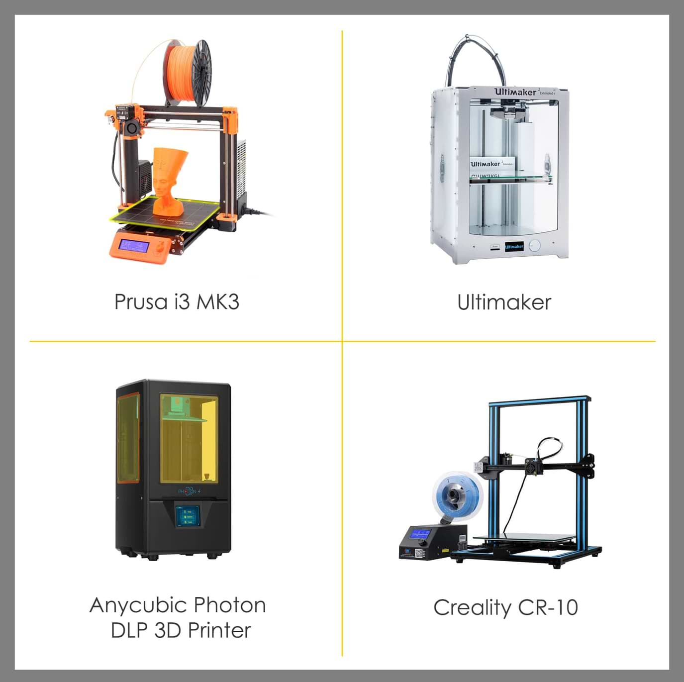
This week, we learned about 3D printers and 3D scanners. It’s very interesting to work on these machines and learn more about the design rules for the printers. In TalentS LAB, we have many different types of 3D printers such as :
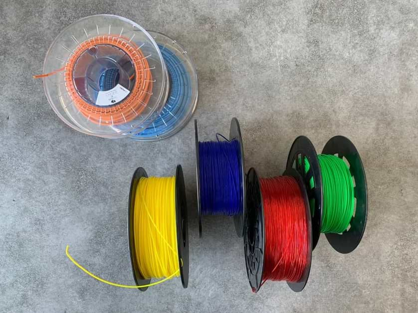
Also, there are many types of filaments that we can use. They include: :
In the group assignment, we were asked to test the design rules for the 3D printer. We researched more about 3D printers on the 3D Hub website.
We also found this poster in the 3D hub. We will use these design rules to get the best results when we design for 3D design.
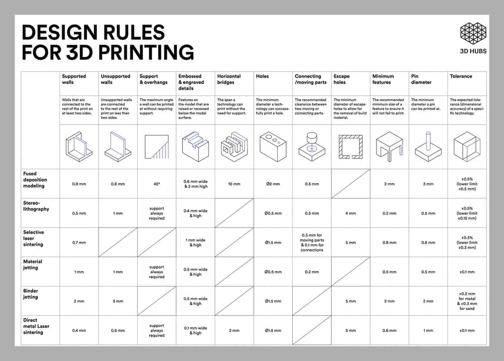
The top 3 things to look out for:
Let’s make the test !
We usually use Prusa i3 MK3 printer. So, we agreed to do the test on it. First, let’s talk more about this machine.
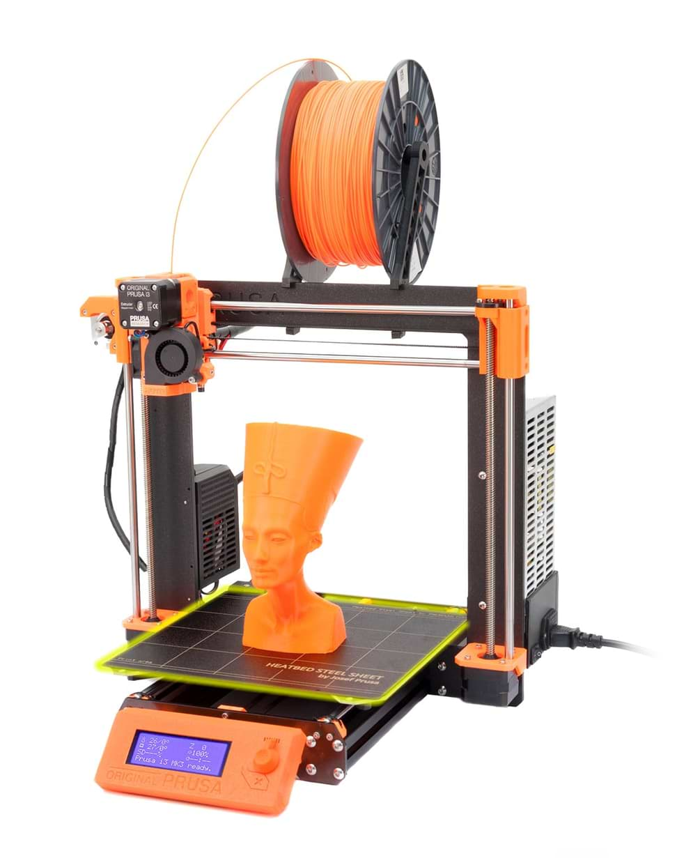
What are the tech specs of the Prusa i3 MK3?
PRINTER SPECS:
SOFTWARE:
PHYSICAL DIMENSIONS:
For more information about Prusa i3 MK3
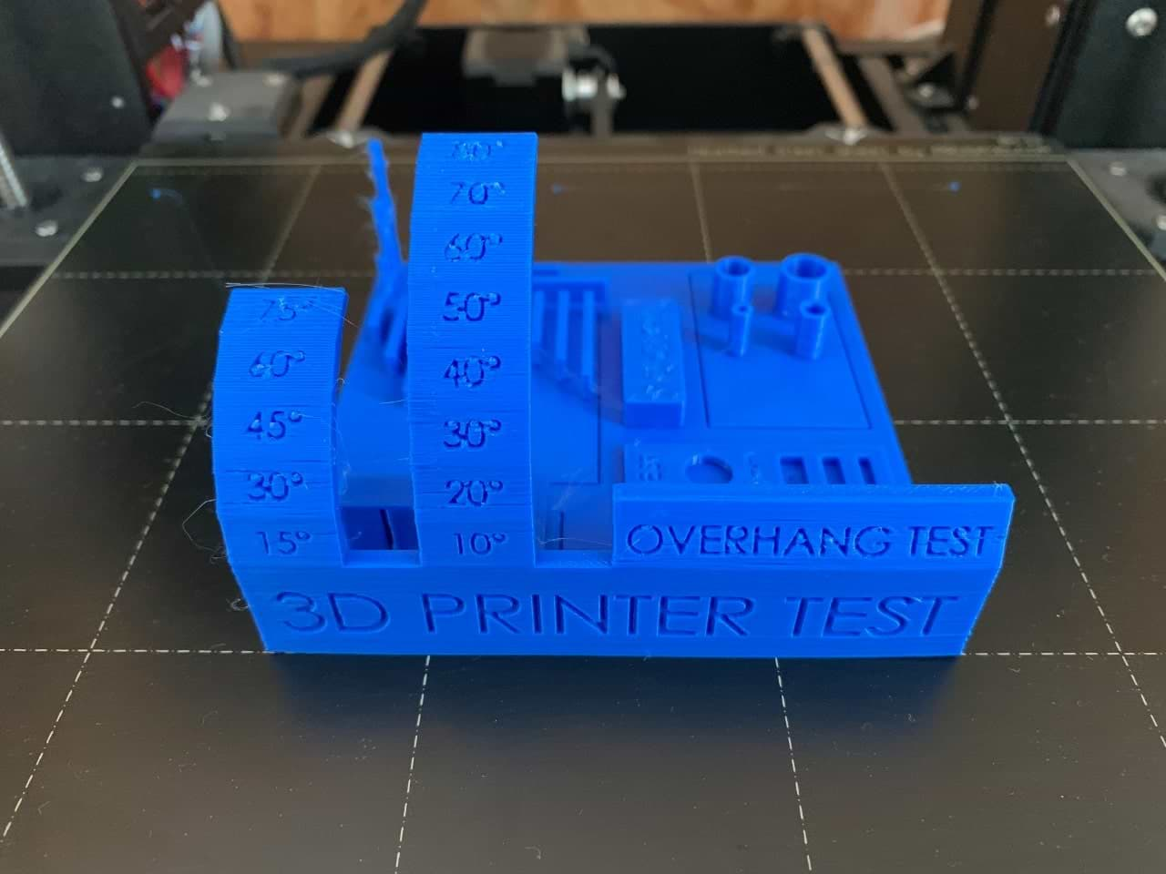
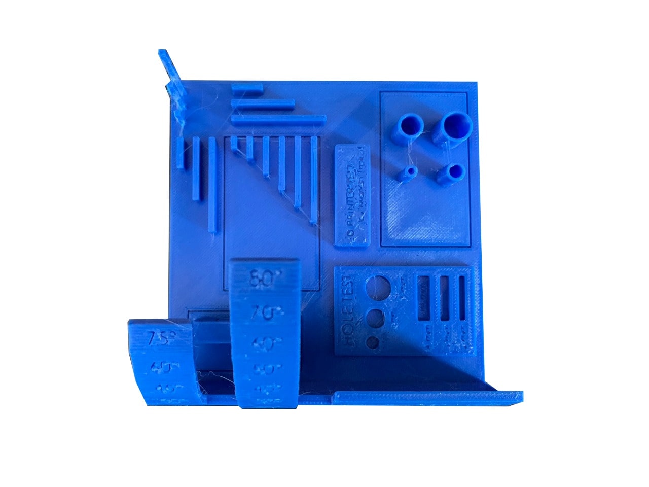
We searched for STL objects to test some of these features. We found this test (All In One 3D Printer test) on Thingiverse website.
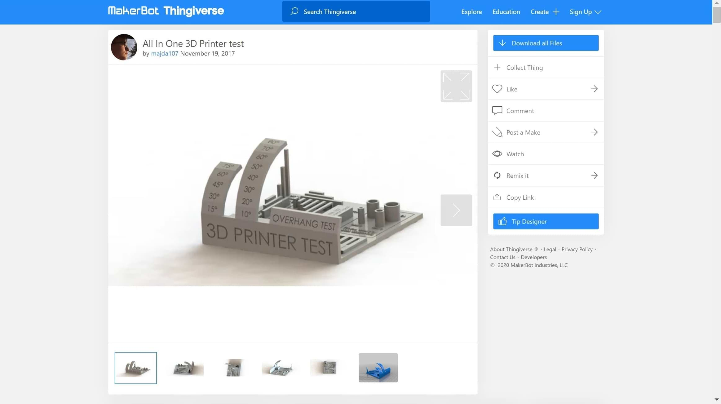
This object will tested the following :
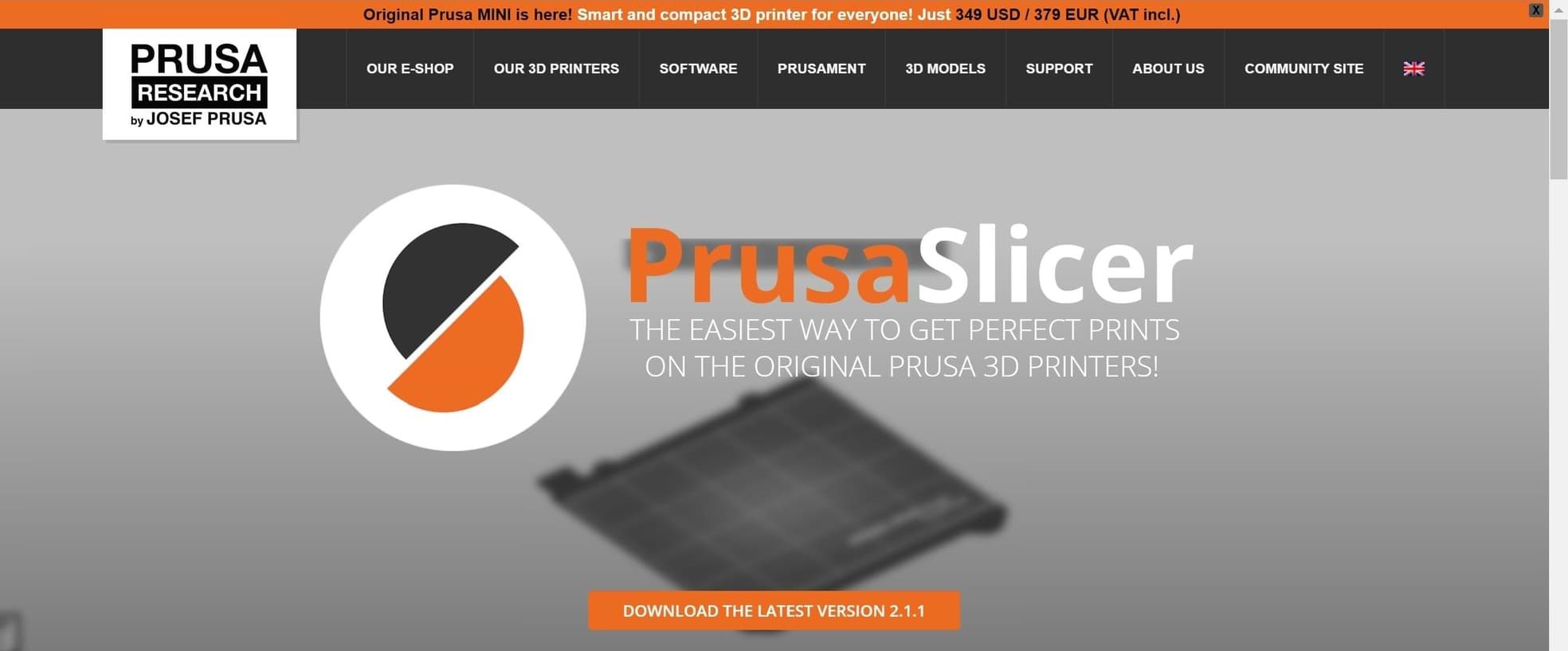
To print the design we had to use Prusa Slicer Software. I will talk in detail about this software in the individual assignment.
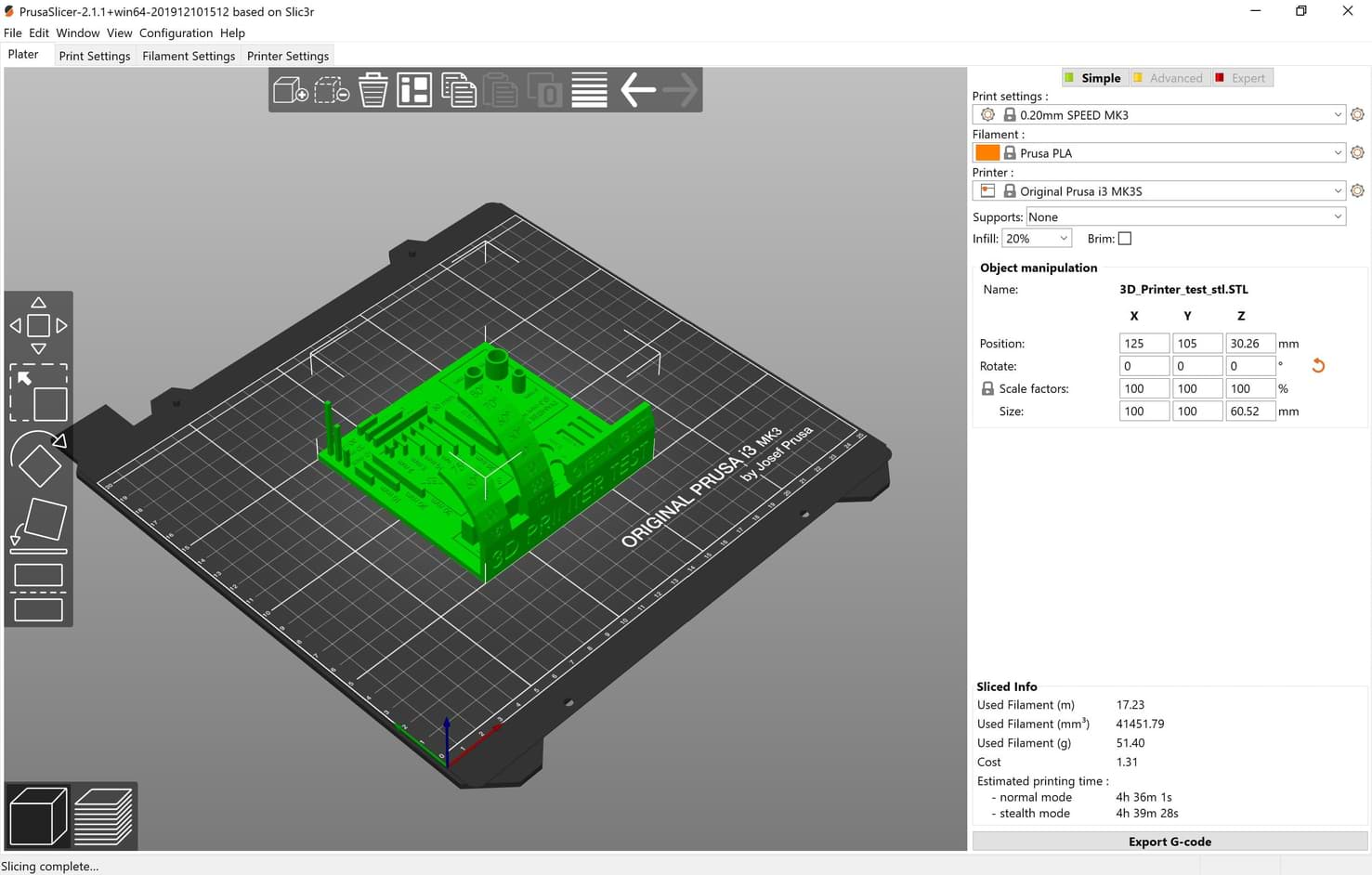
We are using the follwing printing settings :
The result !
Individual Assignment :
In this assignment, I had to design and 3D print an object (small, few cm3, limited by printer time) that could not be easily made in a subtractive manner. We were also asked to 3D scan an object and try to prepare it for printing.
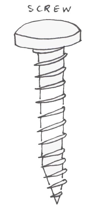
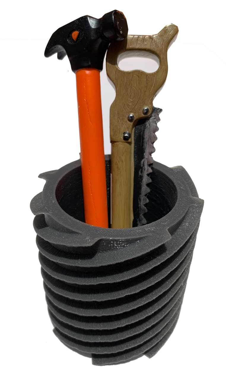
I love hand tools, and I always buy unique pens that look like hand tools, but I don’t have a pen container in them. So, I decided to make pens’ container inspired by screw’s shape.
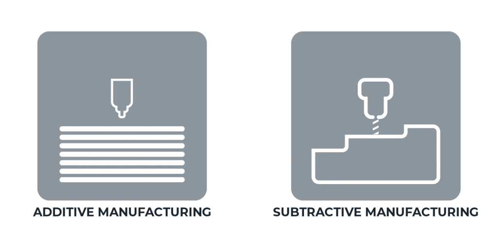
What is the difference between additive and subtractive manufacturing?
Additive manufacturing is a process that adds successive layers of material to create an object such as 3D printing.
Subtractive manufacturing is removing layers of a material by engraving or cutting it away such as a CNC machine.
Why can't this container be made in a subtractive manner?
The object is a cylinder with threads . We can’t make cylinders by using subtractive machines unless by using living henges to be curved. Secondly, the difficult part of this object is the threads that swept around the cylinder. It is impossible to make threads in subtractive machines.
Let’s Design !
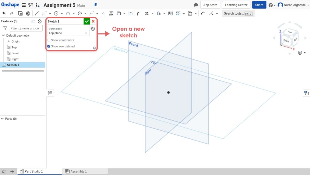
I’m going to use OnShape software to design the container.
1. Open Onshape software > open a new sketch.
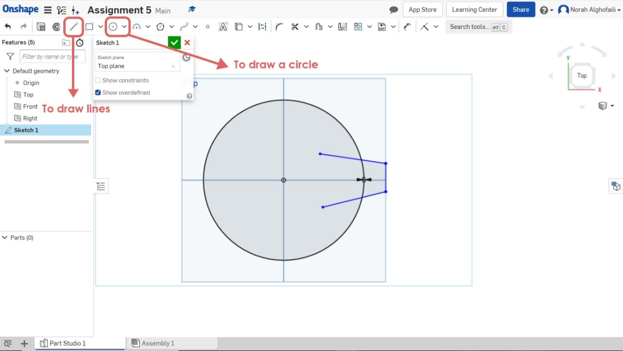
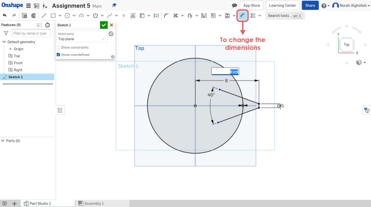
2. Draw a circle and an angle by using line.
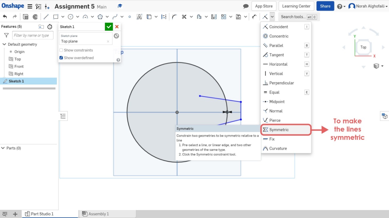
3. Use symmetric tool to make the geometric shape symmetric relative to a line and change the dimensions.
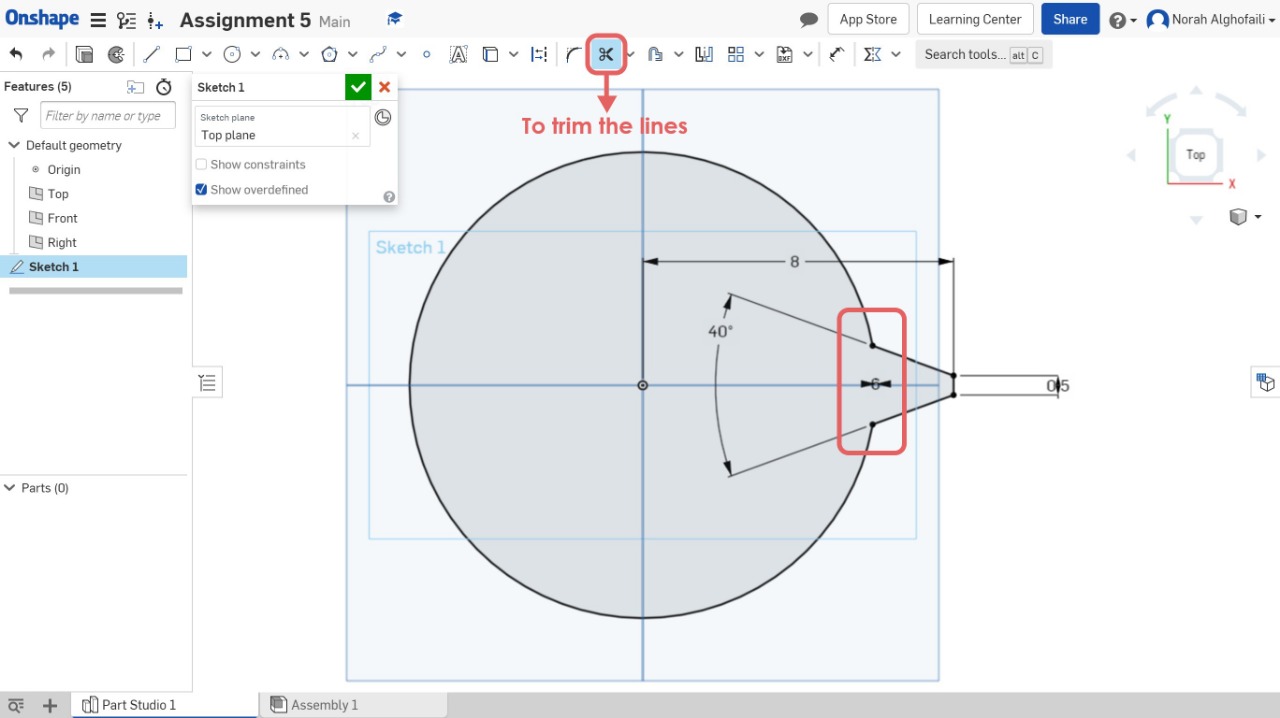
4. Use the trem tool to remove some lines.
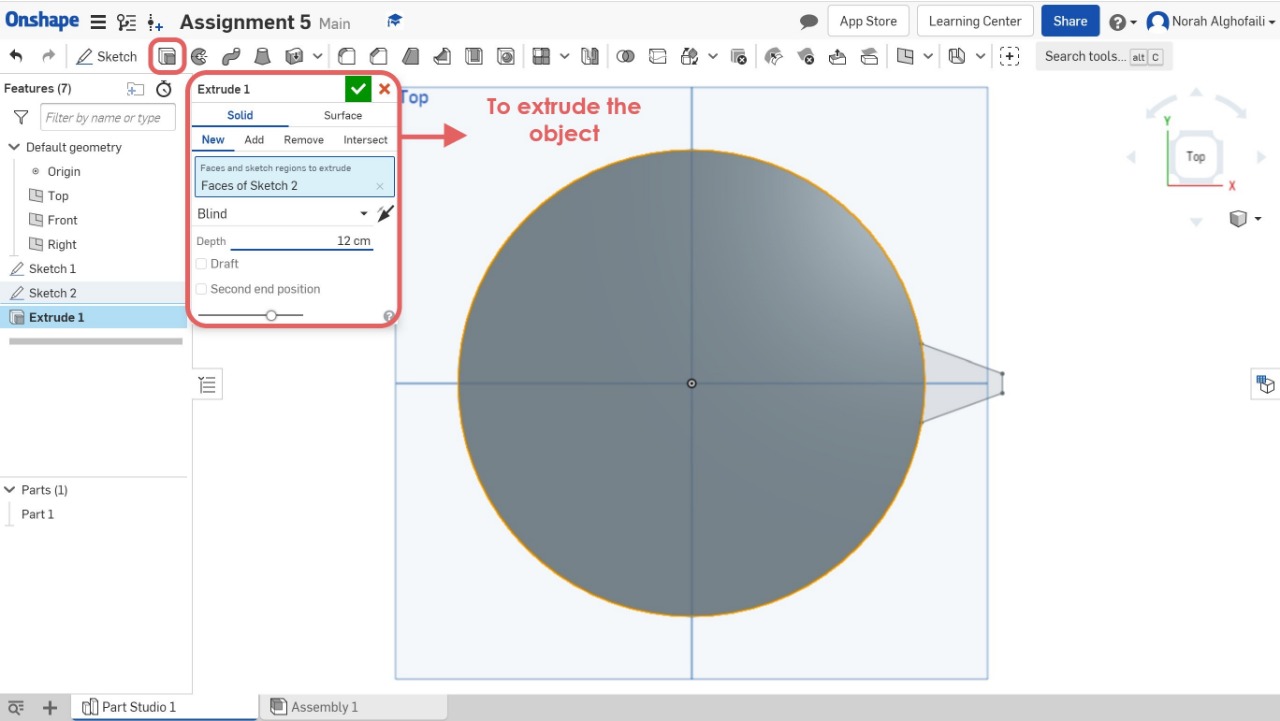
5. Open a new sketch and draw a circle > Then use extrude tool to make a depth for the circle.
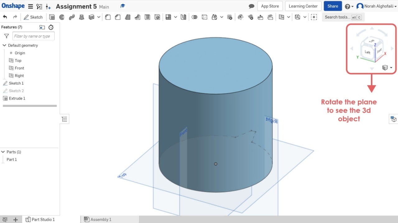
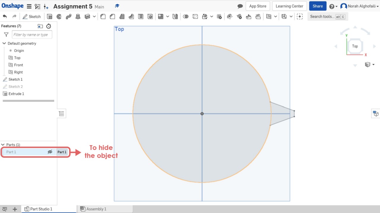
6. Hide the object.
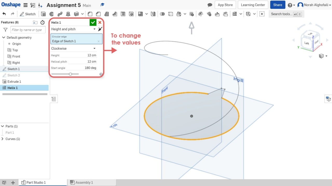
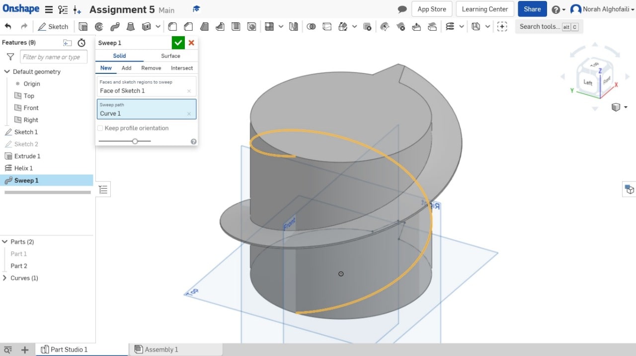
7. Use Helix tool to create a circular geometry > Select height and path > select the edge of the sketch and change the values.
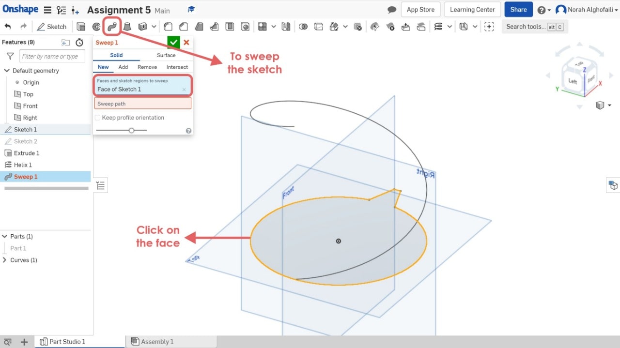
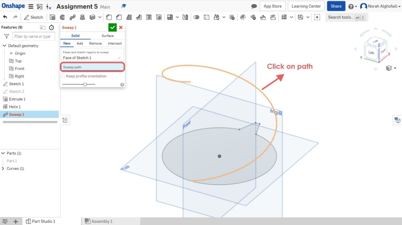
8. Use the sweep tool > Select the face sketch > Then select the sweep path.
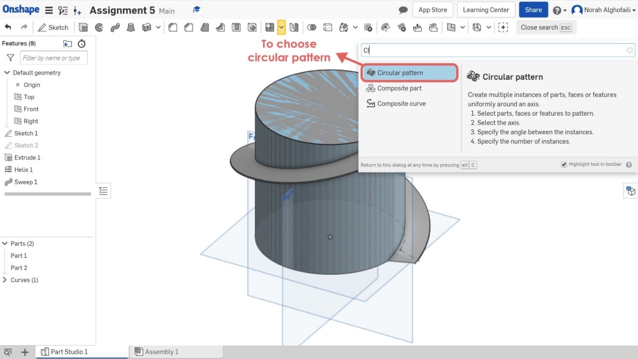
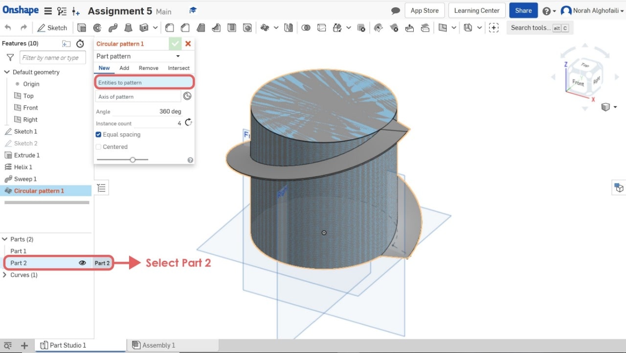
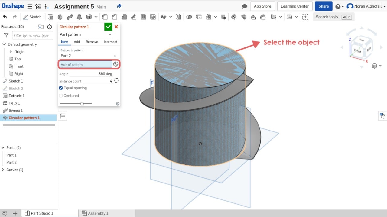
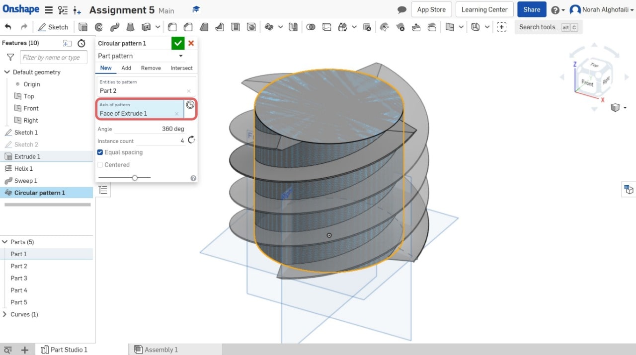
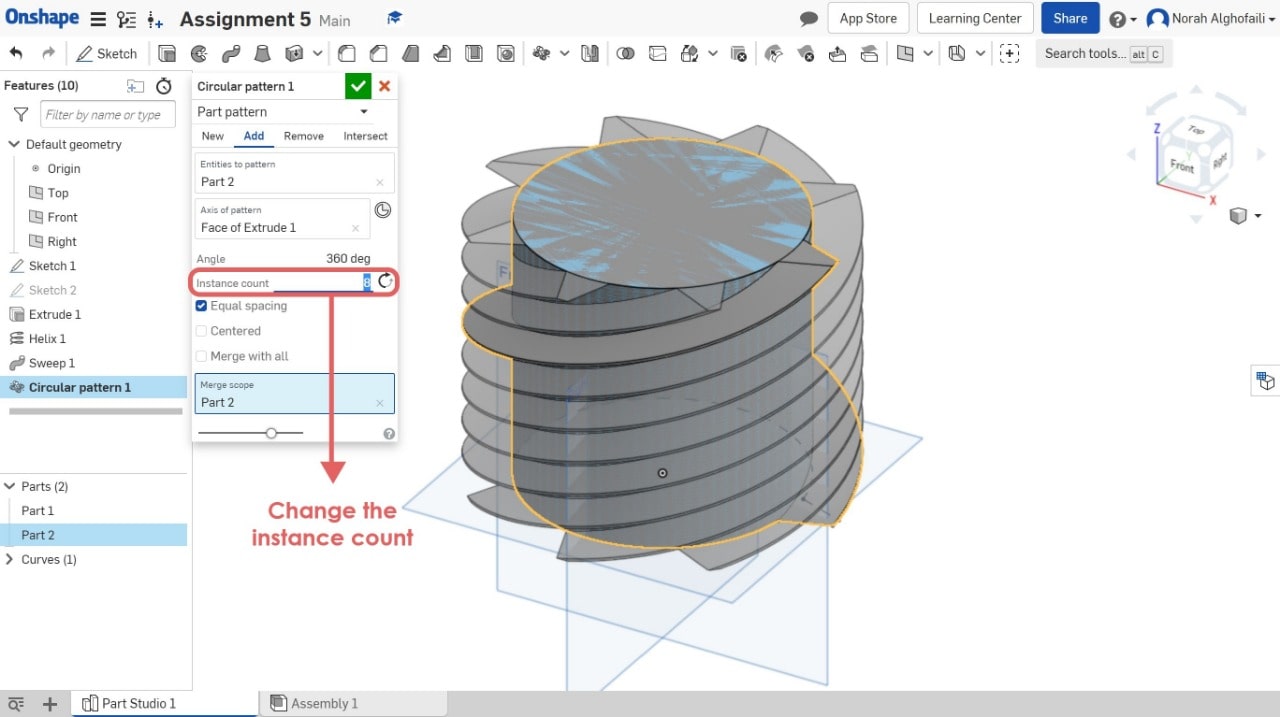
9. Use circular pattern tool > Select part 2.
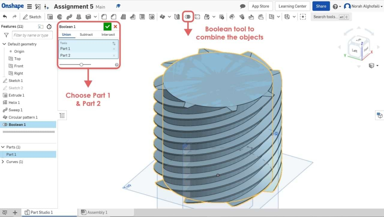
10. Use the Boolean tool to combine two objects > Select part 1 and part 2.
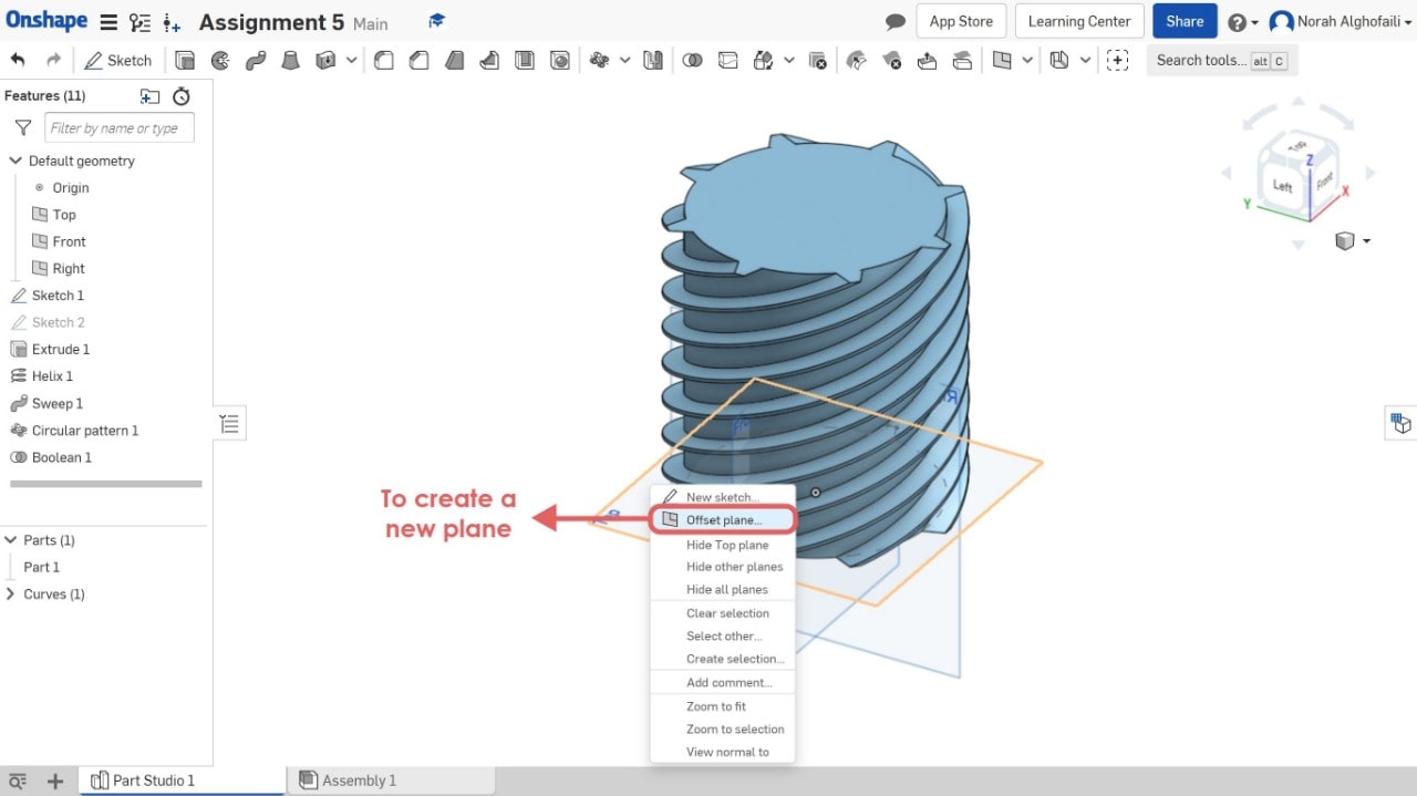
11. To create a new plane with different z axis > Select a plane > Right click > Offset plane.
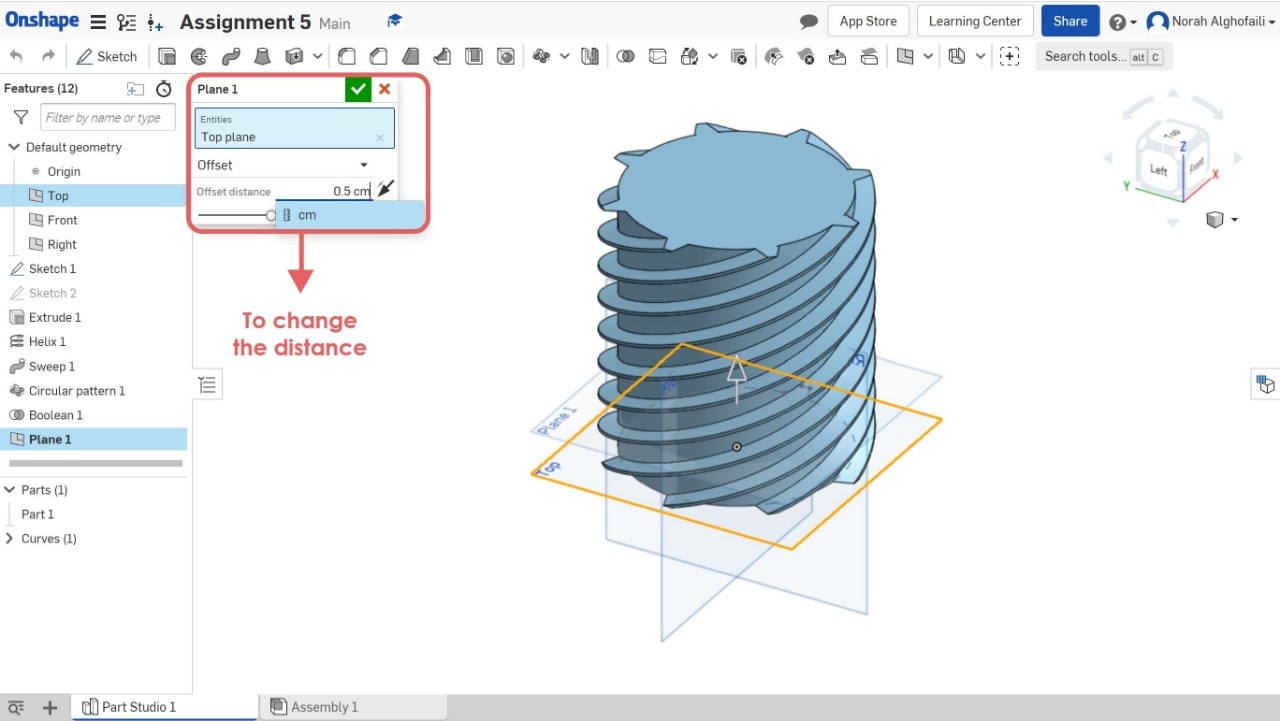
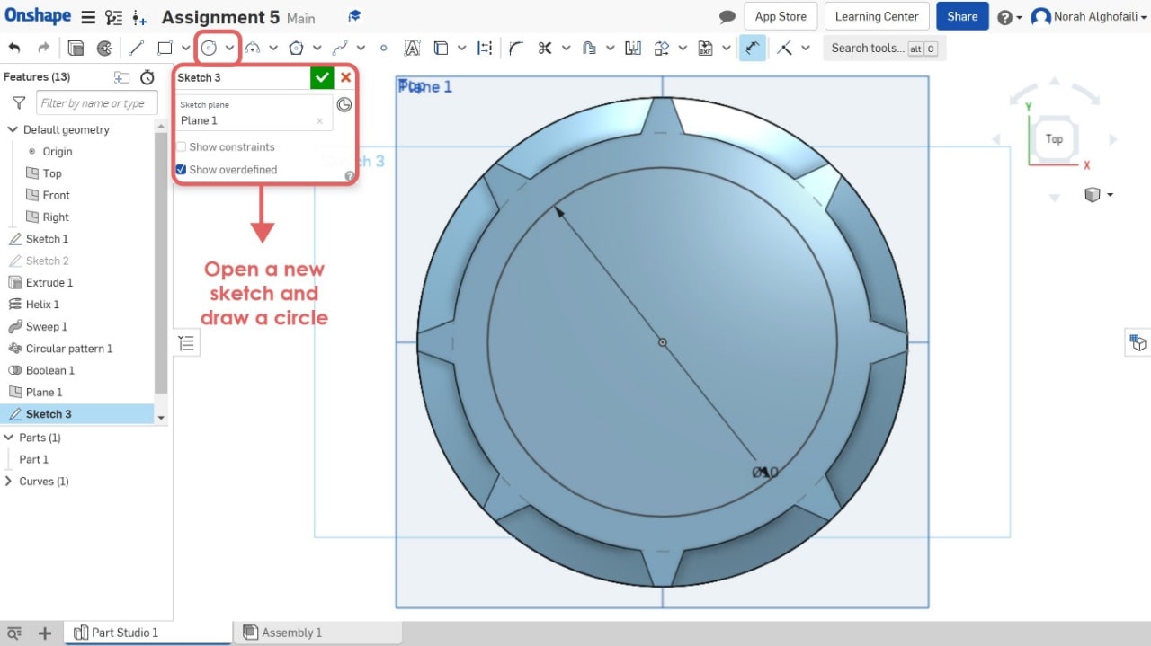
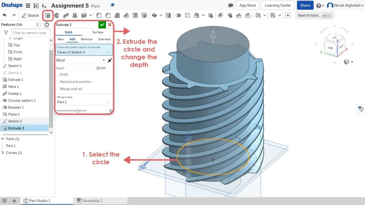
12. Create a new sketch > select the new plane > draw a circle > use extrude tool to make a depth of the object
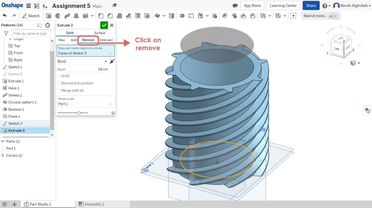
13. Change the height > Chose remove to subtract the new object from the previous one.
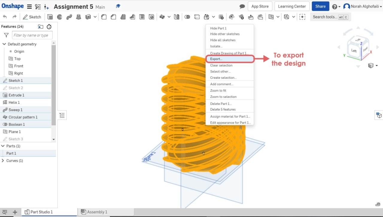
WAHOOOO NOW WE HAVE THE FINAL MODEL ! Let's save it. How do we do that?
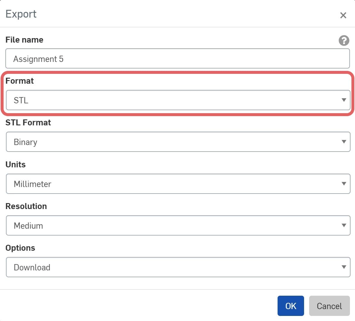
To save the model > Select the model > Right click > Export > Save it as STL.
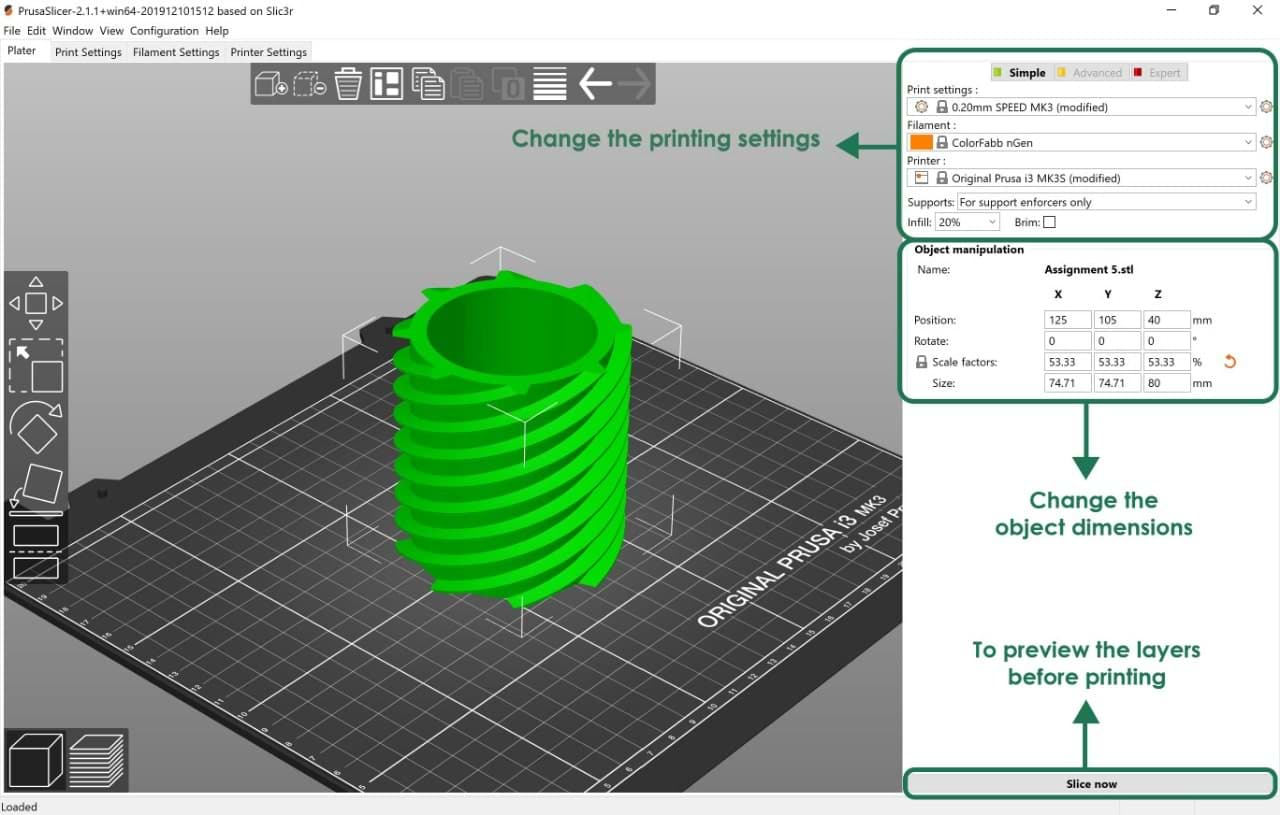
I used Prusa Slicer to import the model and do the printing settings.

What is PrusaSlicer software ?
PrusaSlicer is a software that takes 3D models (STL, OBJ, AMF) and converts them into G-code. PrusaSlicer has a simple user interface.
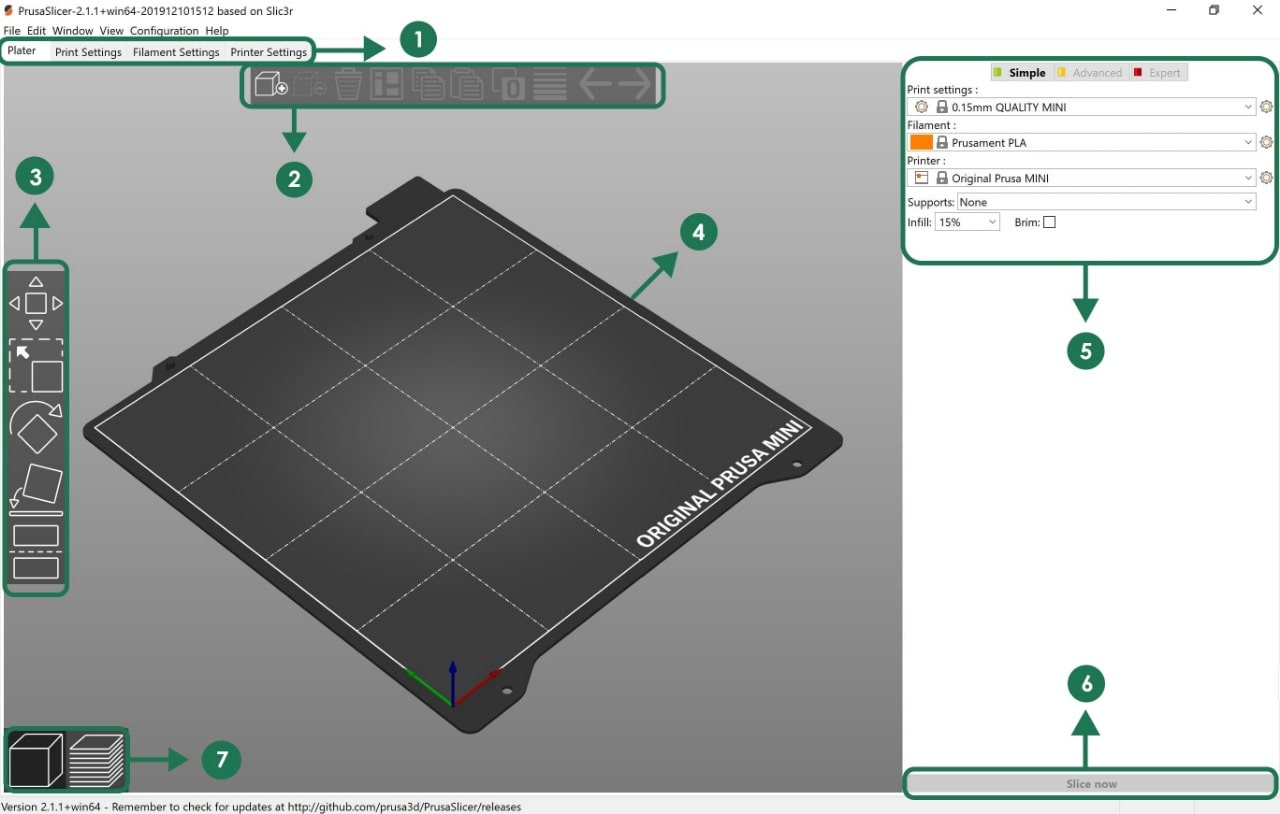
The main parts :
1. Opens detailed settings of print, filament and printer.
2. To load or delete models into PrusaSlicer.
3. Move, Scale, Rotate, Place on Face and Cut tools.
4. Model preview on the plate.
5. Switch between Simple / Advanced / Expert mode in order to change the following: Quality / Speed setting of a print.
6. Slice and generate a G-code button.
7. Switch between 3D editor and layers preview.
How do you use PrusaSlicer software ?
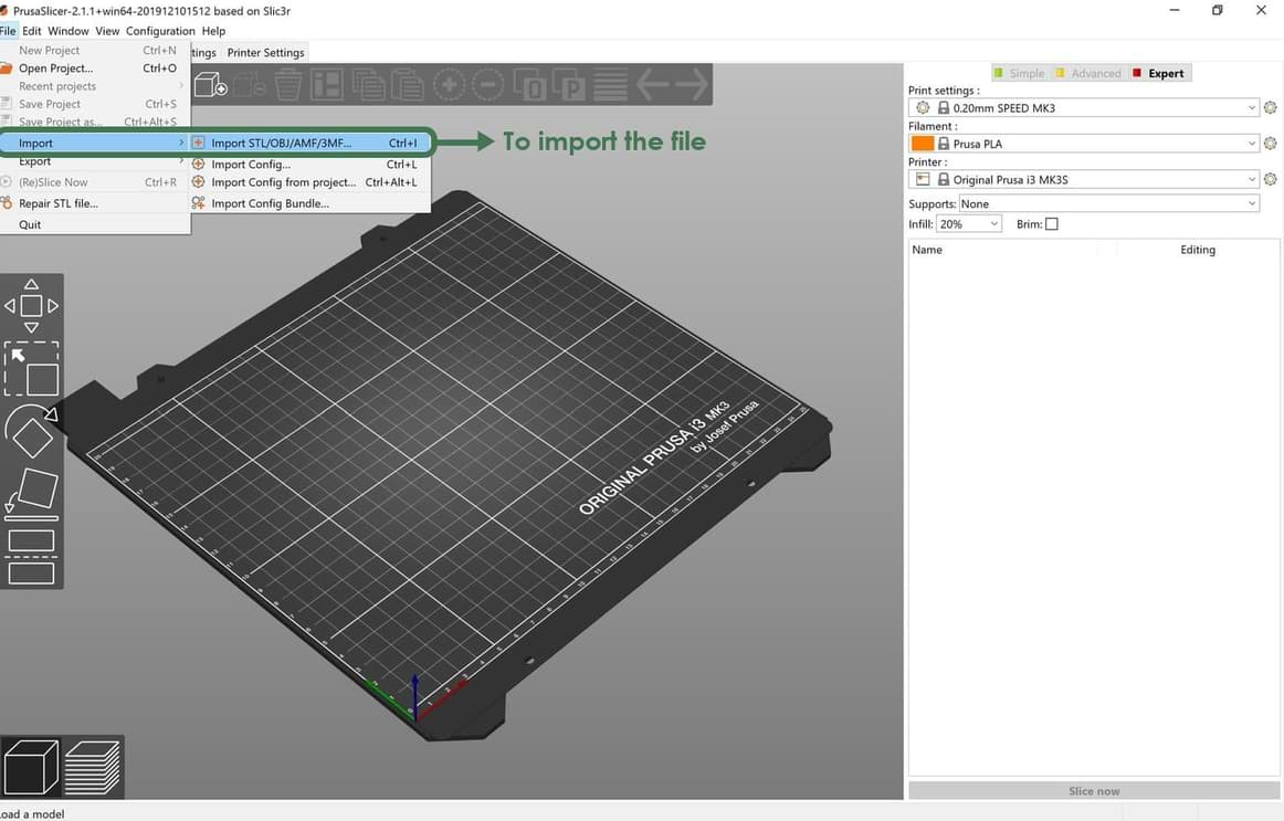
1. Go to File > Import the STL file.
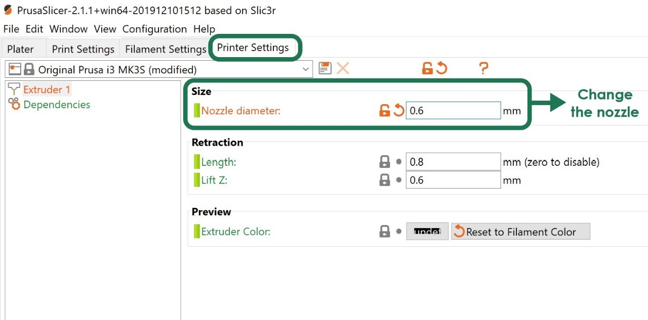
2. Change the settings:
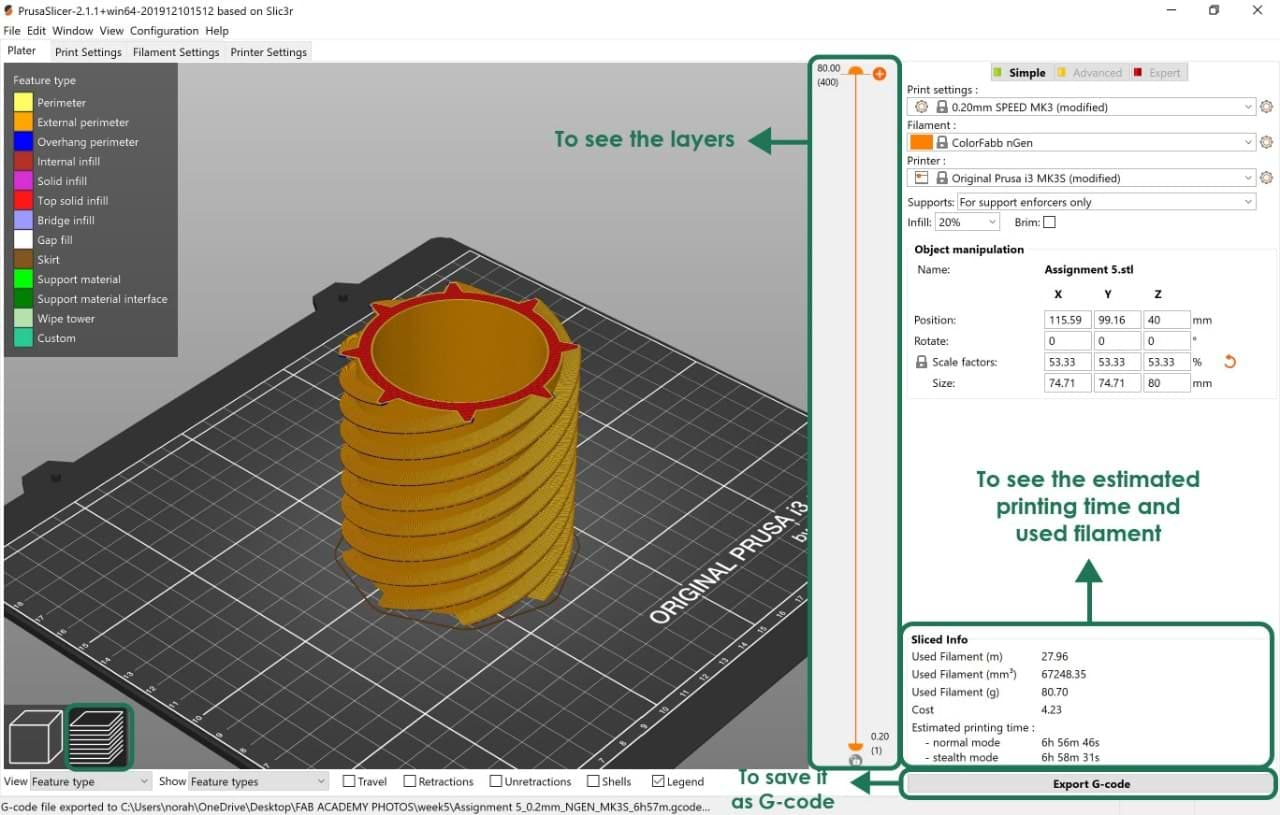
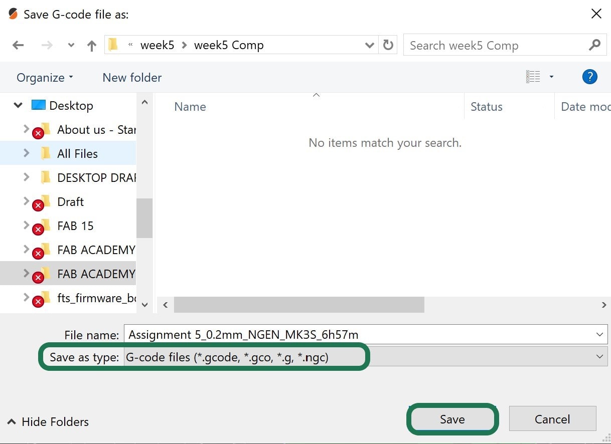
3. To preview the layers before printing, go to > Slice now > Export G-code.
Let's Print!
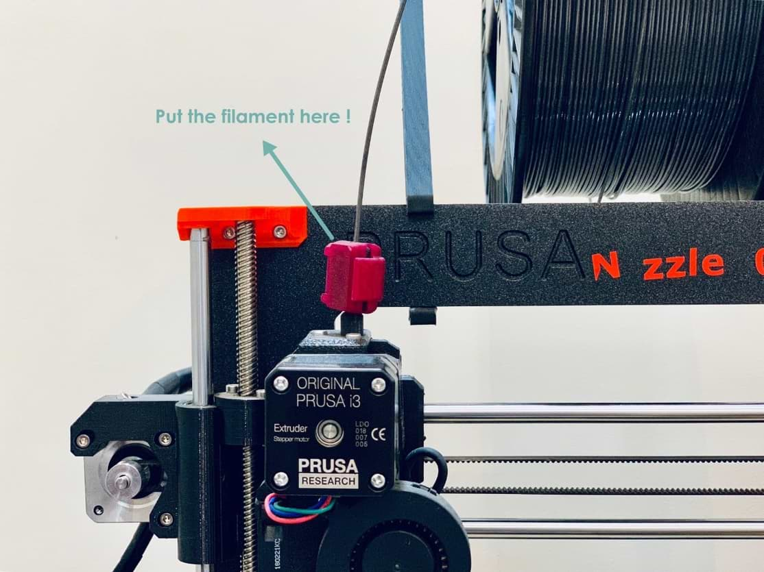
How do you use a Prusa 3D Printer?
1. Turn on the power switch.
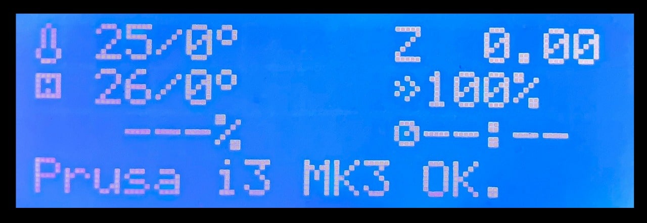
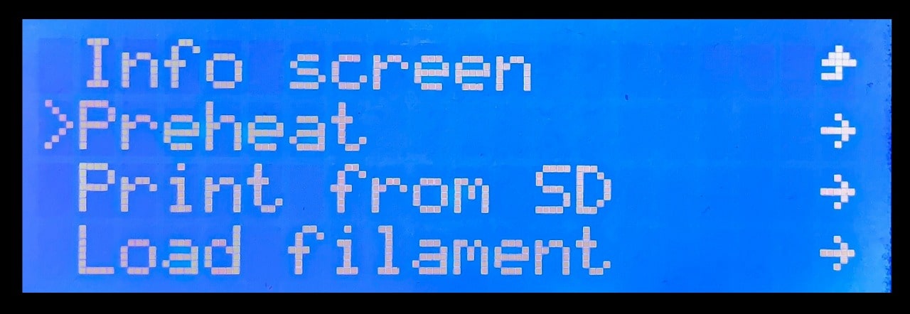
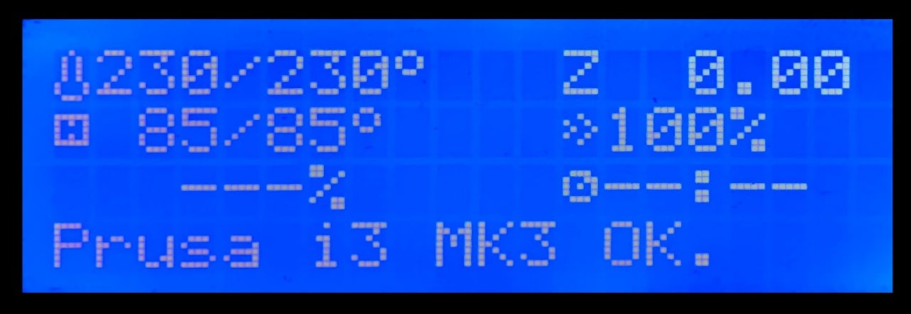
2. Load the filament ( I used ColorFabb nGen gray color ) > Preheat to load.
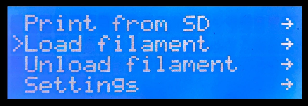
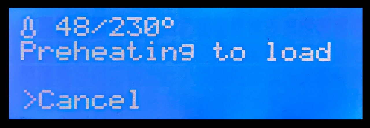
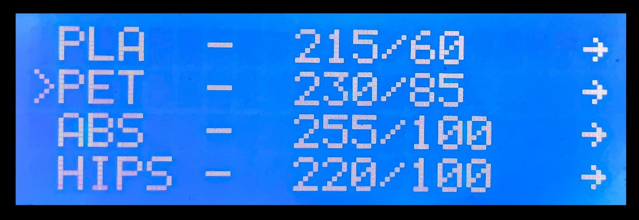
3. To start printing > Go to preheat > Choose the filament > nozzle temperature = 230 / heated bed = 85.
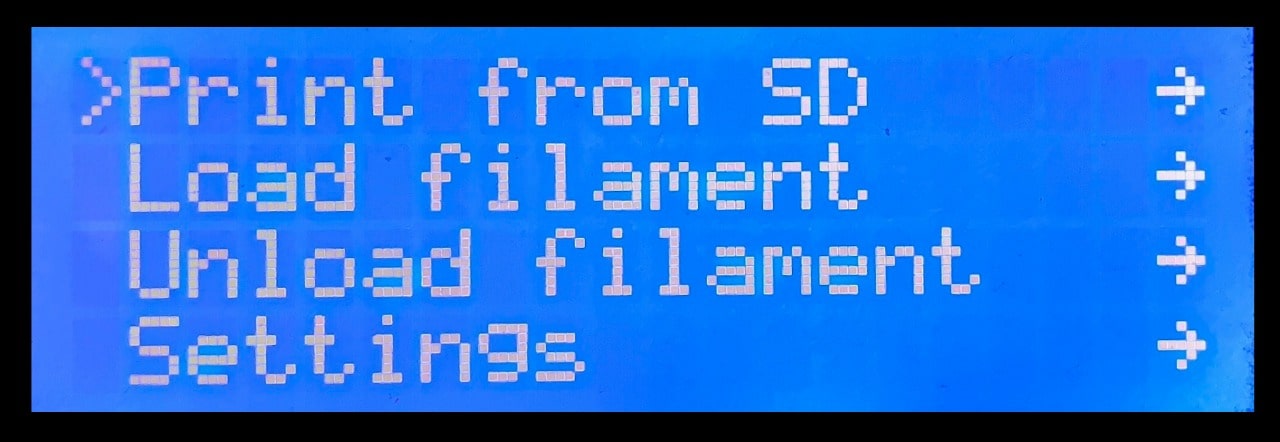
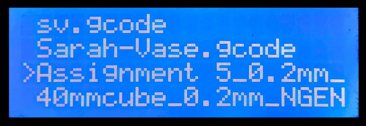
4. To select the G-Code file > Go to print from SD Card > Choose the file.
5. The printer will start printing when the temperature reaches the same degree.
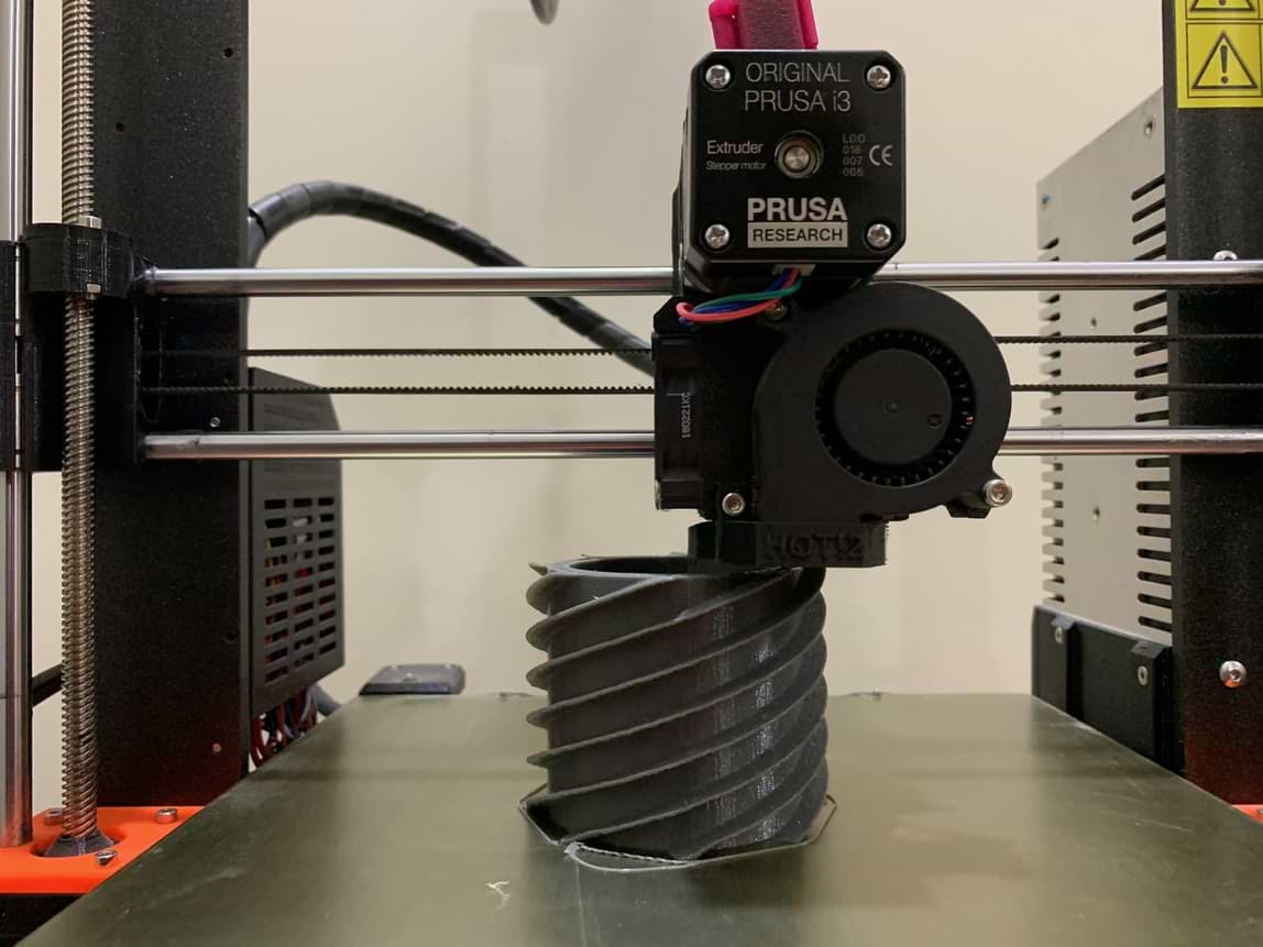
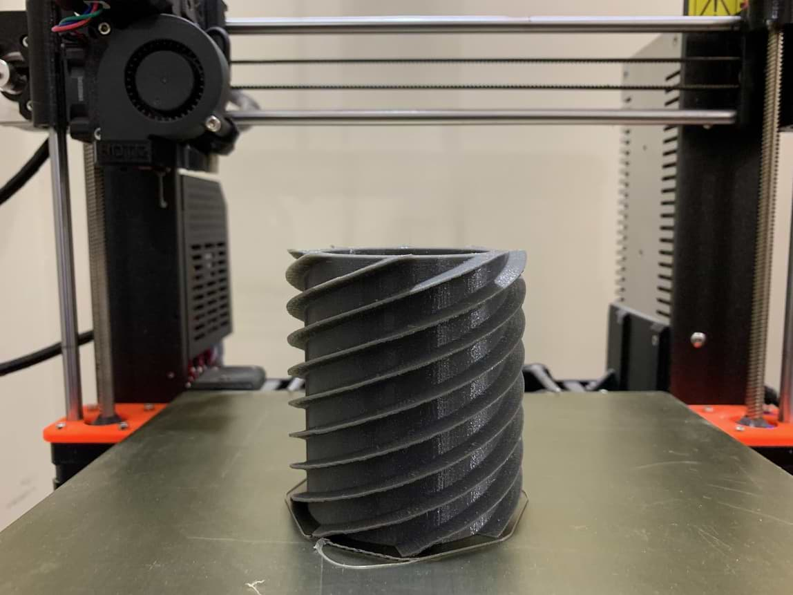
Wooow! This is the final result !!
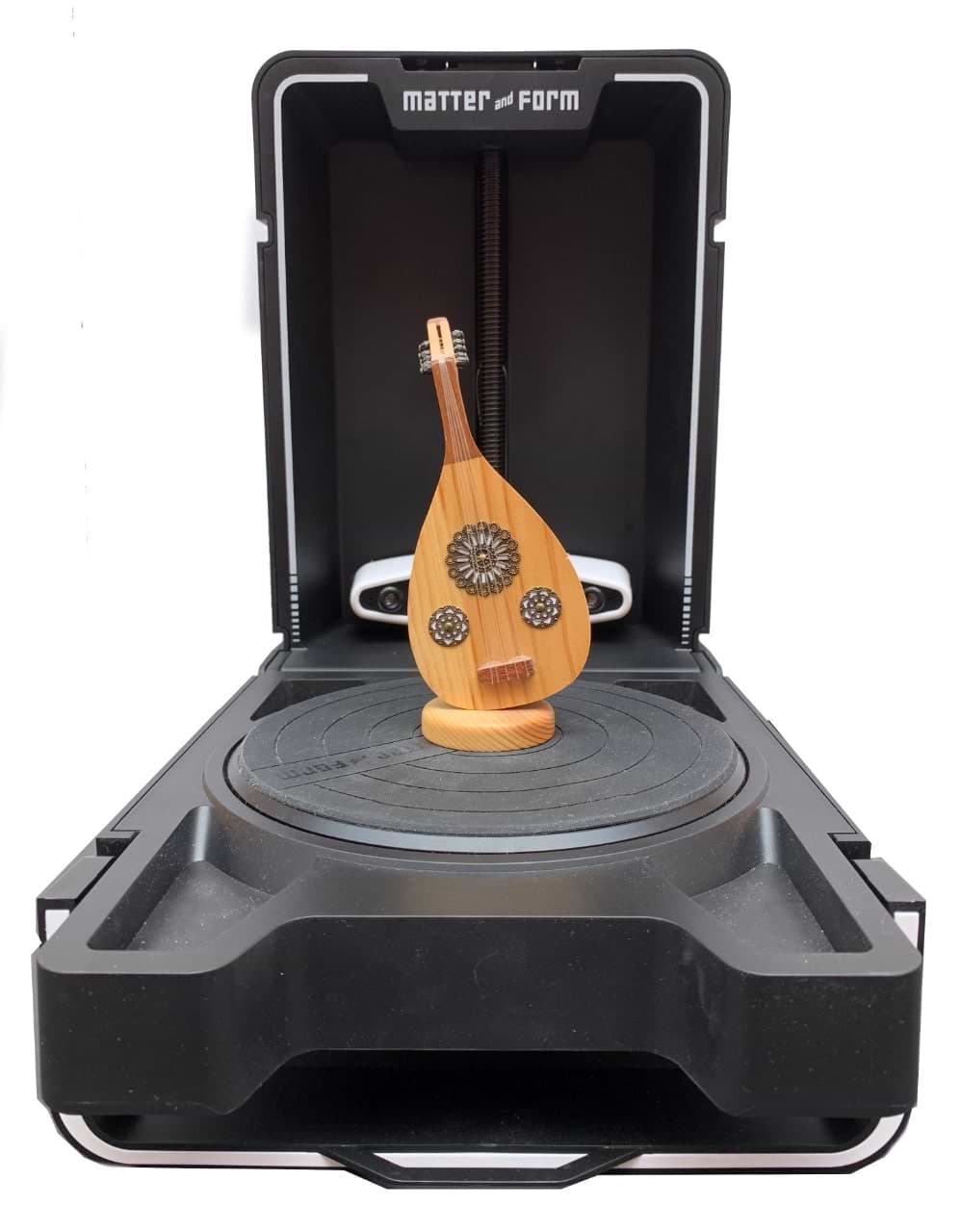
Let’s Scan !
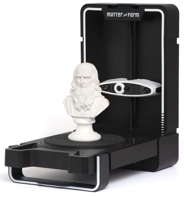
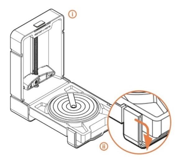
In TalentS LAB, we have Form and Matter 3D Scanner. This is my first time using a 3D scanner. really easy to use this machine even for a first timer.
Specifications :
SCAN ACCURACY
MAXIMUM OBJECT SIZE AND WEIGHT
SCANNER SIZE AND WEIGHT
SOFTWARE
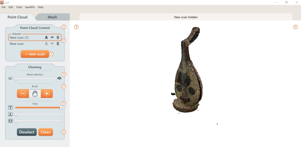
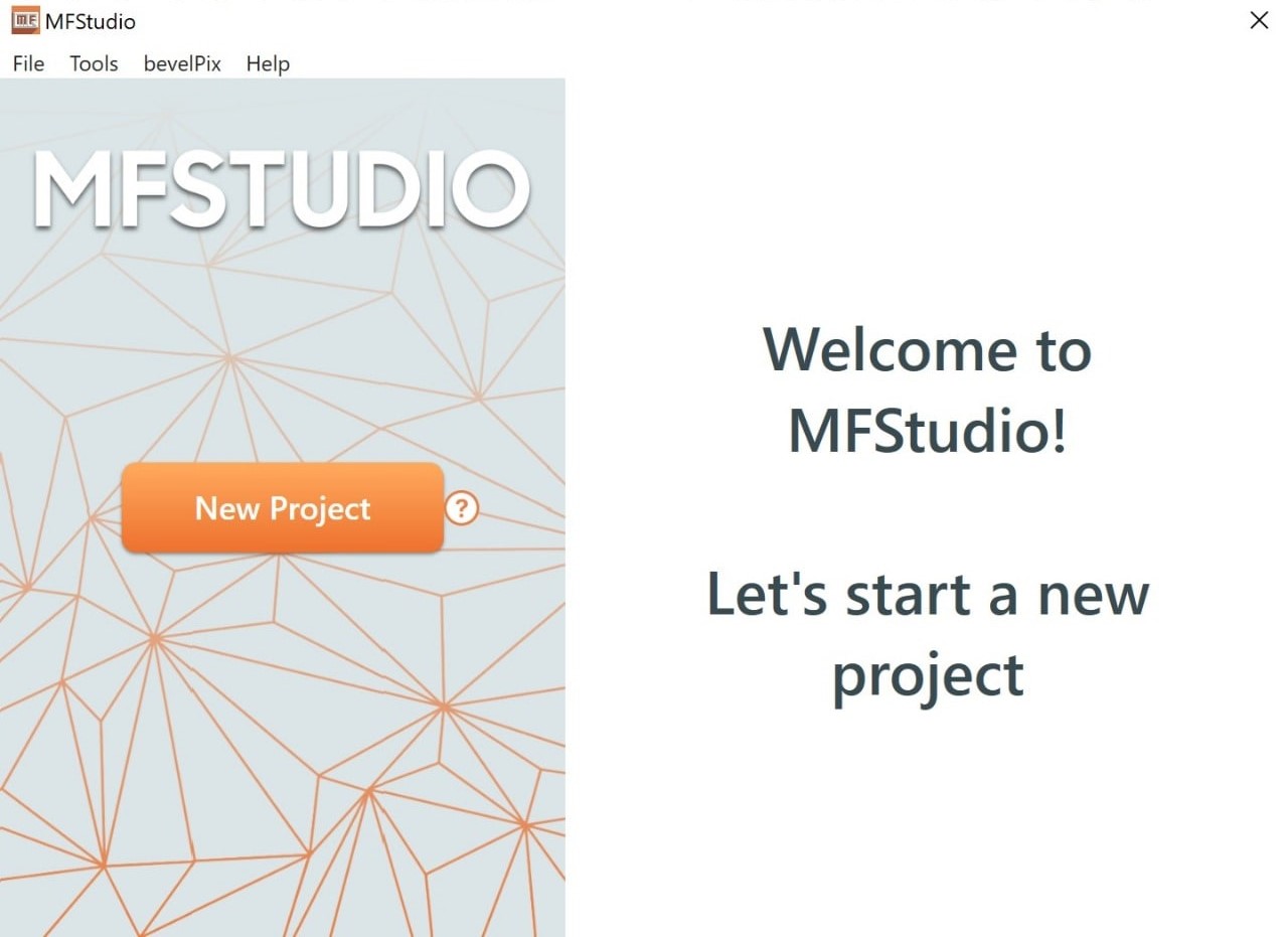
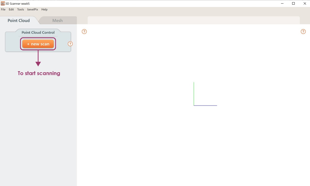
To start scanning the object I will use MF Studio software.
How do you use it ?
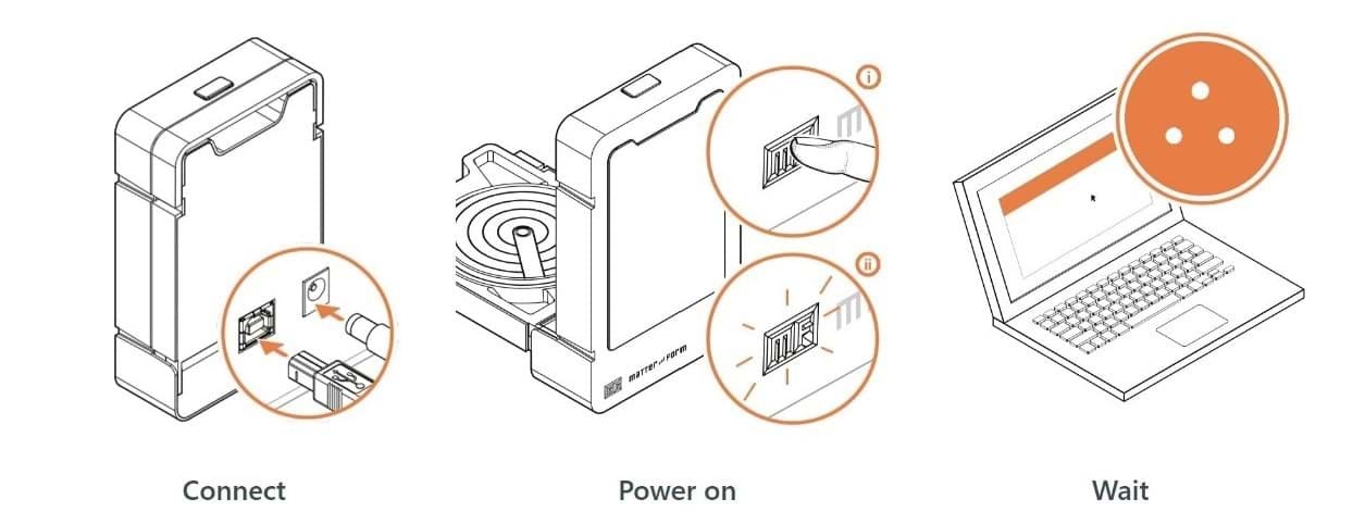
1. Connect the power cable of the scanner and turn it on.
2. Open MF Studio software.
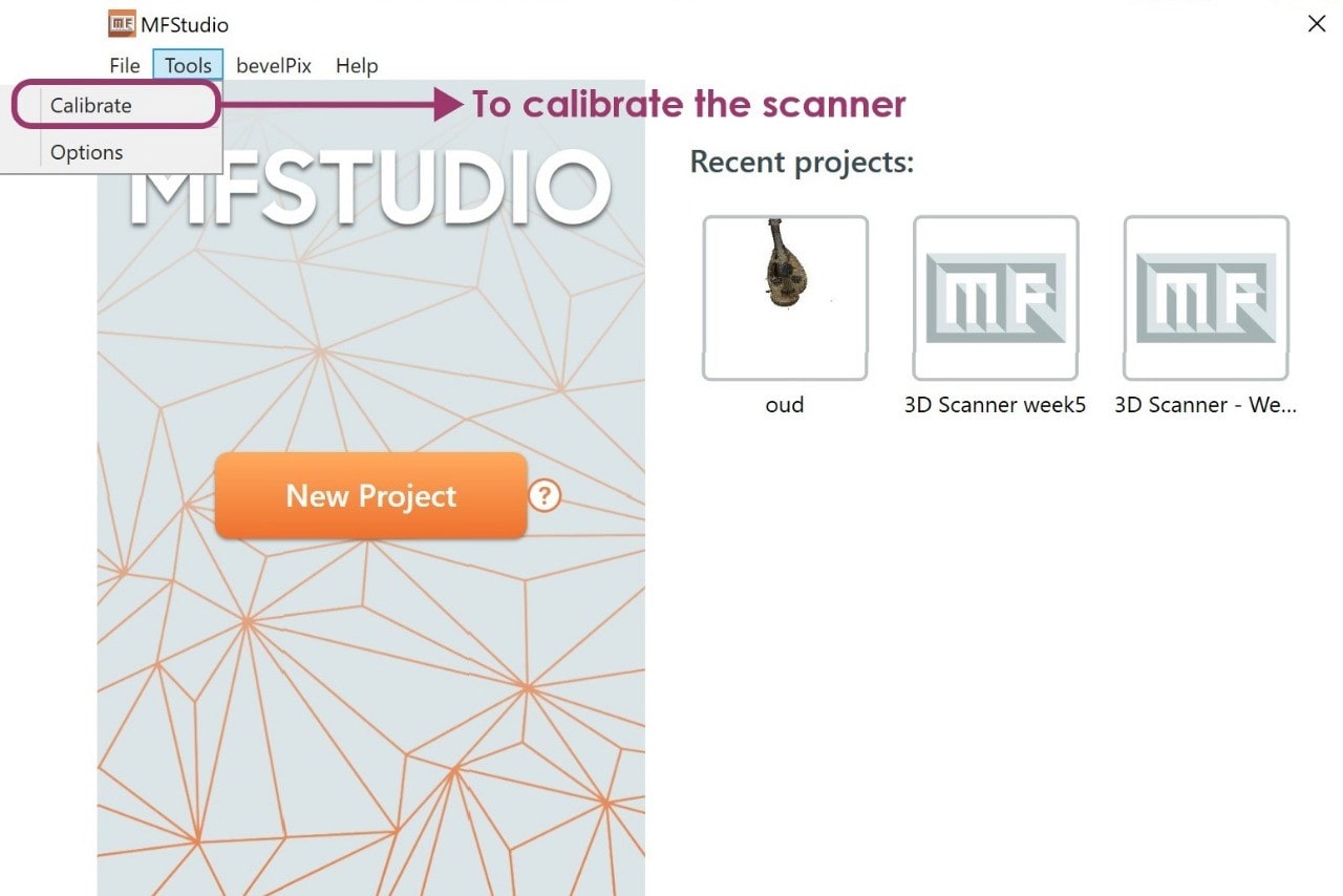
3. Go to Tools > Calibrate.
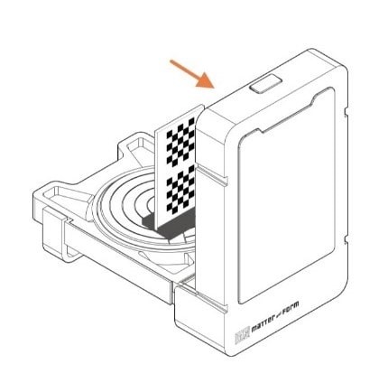
4. Place the scanner in area where the lighting is ambient > Then click on continue.
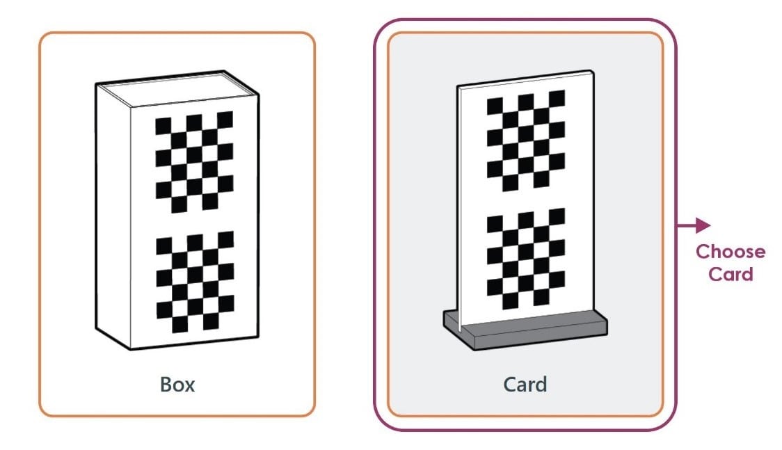
5. To calibrate the scanner > chose card > Attack the base to the card.
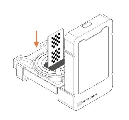
6. Put the card in the center on the scanner > Click on calibrate.

7. Put the card toward the camera > Click on continue.
8. Move the card 2cm toward the camera > Click on continue.
Wow! It’s Done!
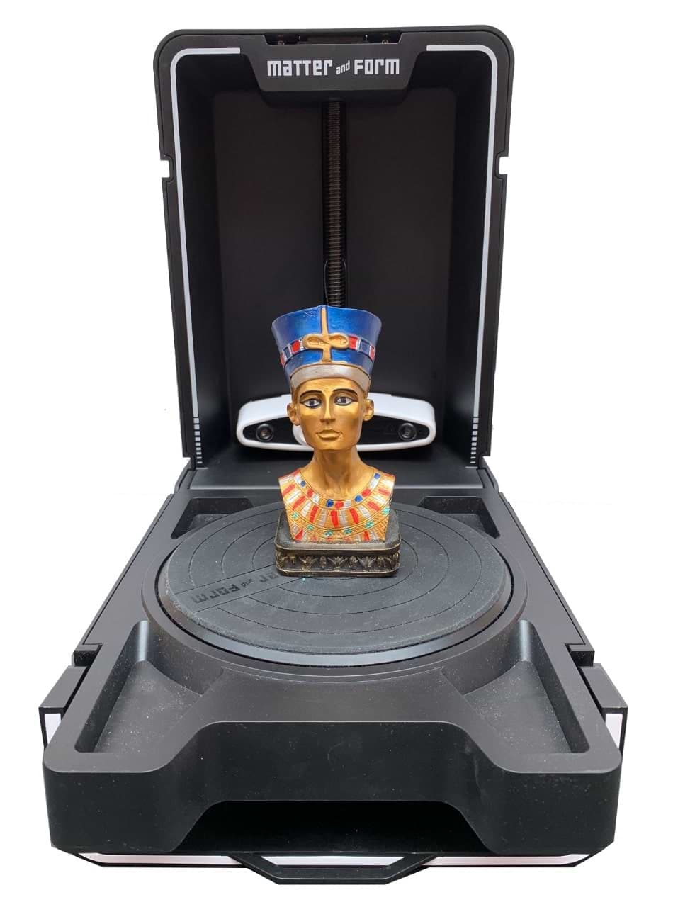
Now, let’s Scan !
I bought this souvenir when I visited Egypt last year to attend the Fab15 conference. It’s Nefertiti ! I decided to scan this 3D object with it.
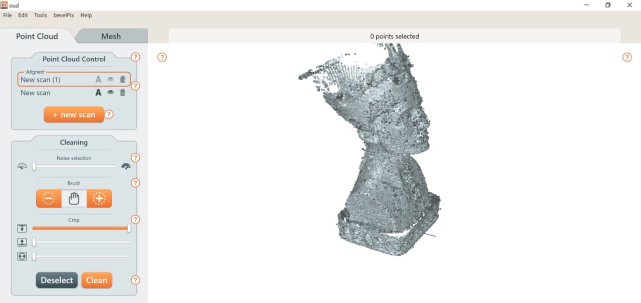
I also scanned another object to test the machine.