This is a new topic !! It looks interesting !!
Networking and communications impact our daily life. The fact that the importance of network technology in our daily life is undeniable has inspired scientists to make improvements from time to time through their invented tools and devices for us to use, just to make our lives easier. Technology can help not just with the present but also approximating the future. I am so excited to dig deeper in this topic to learn how networking and communications work!
In this assignment, we must use two different boards to communicate with each other.
We are supposed to design, build, and connect wired or wireless node(s) with network or bus addresses. I searched about communications protocols and networks with microcontrollers . I think that I got enough information to start this assignment!
First, I’m going to define networking and communication.
What is networking and communication ?
Communication data refers to the transmission of digital data between two or more computer devices. A data network allows computers to exchange data by using either wire or wireless media.
The best example of a computer network is the Internet.
A computer network has four types:
What are the protocols ?
A networking protocol determines how data is transmitted between different devices. It also allows connected devices to communicate and interact with each other. The purpose of networking protocol is to enable the devices to understand the electronic signals they send to each other over network connections. Without protocols, devices would lack this function.
Network protocols are the reason we can easily communicate with people all over the world. Nowadays, we can not live without networking!
As humans we can communicate with each other by using different languages. Similarly, machines like the Arduino boards communicate using specific communication protocols. We can classify the protocols into two categories :
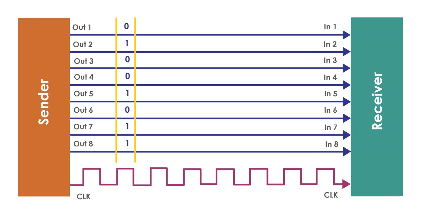
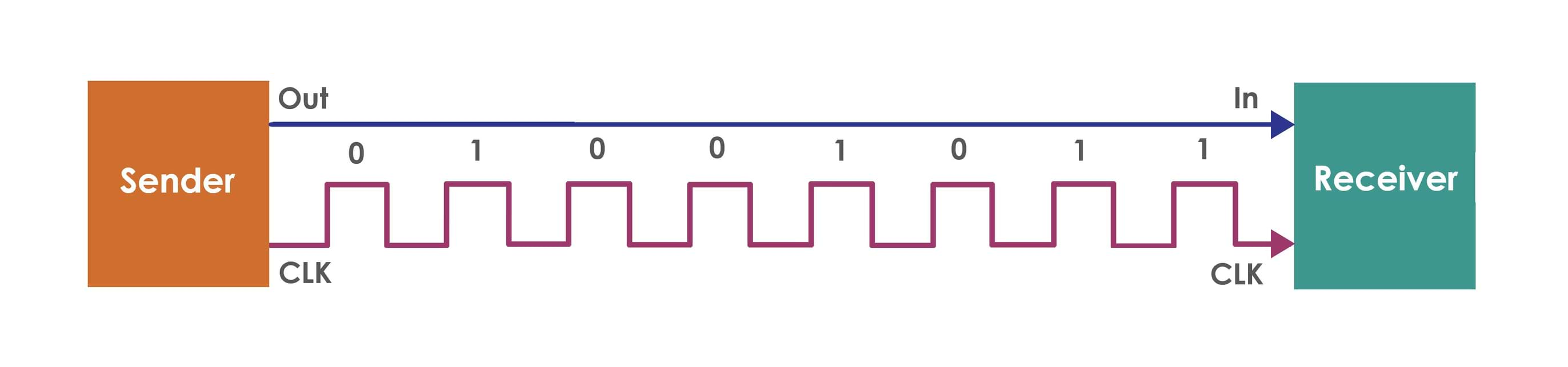
There are standard serial wired communication protocols such as :
There are standard serial wireless communication protocols such as :
In this assignment, I’m going to focus on I2C protocol to communicate the Arduino boards with each other.
Why did I choose the I2C protocol ?
What is I2C communication protocol and how does it work?
I2C Communication is a serial protocol which has two signals, along wires with a power and ground connection. They will be connected across two devices. The first device acts as master and the other device acts as a slave.
The two signal wires are :
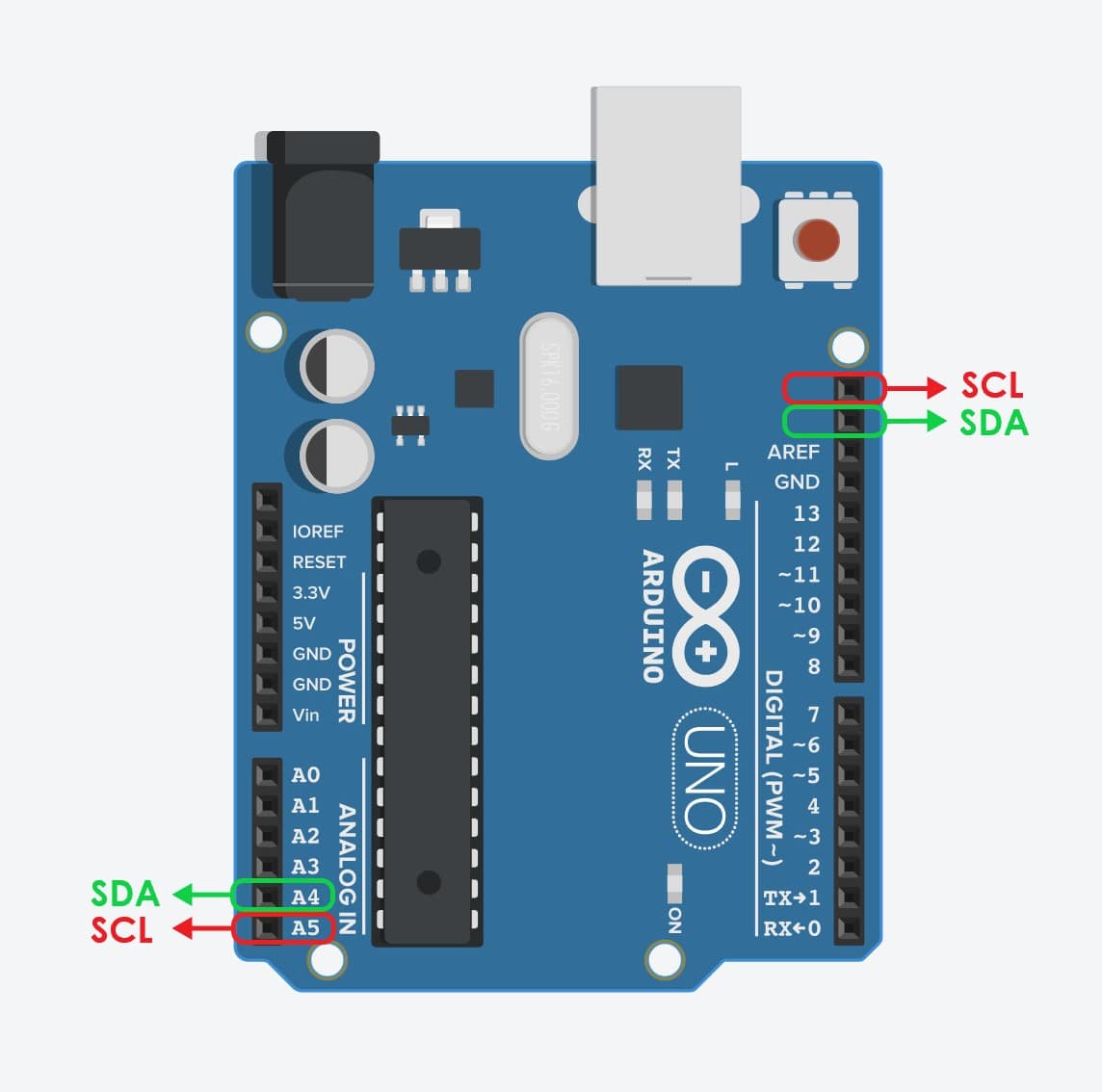
Arduino I2C Pins :
The Arduino Uno board has only one I2C module, but it provides these SDA and SCL line at two different locations. To connect these two signals in the Arduino boards, we can use the following pins:
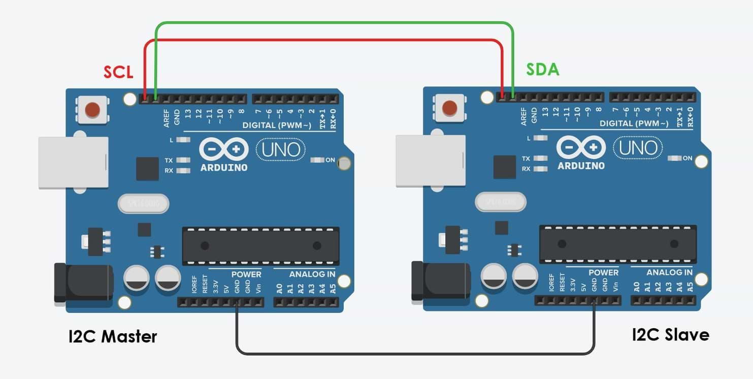
Master and Slave Devices
How does master and slave devices work ?
The master device will be programmed to control the bus and supply the clock signal in order to give order. The slave device will receive the order and react.
Arduino Wire Library
With I2C protocol we are going to use a built-in Arduino library called the Wire Library. This library can configure the Arduino to become either a master or slave.
I2C functions for Arduino:
Wire.write (data) :
It will be completed soon.
Arduino Boards Connection Test :
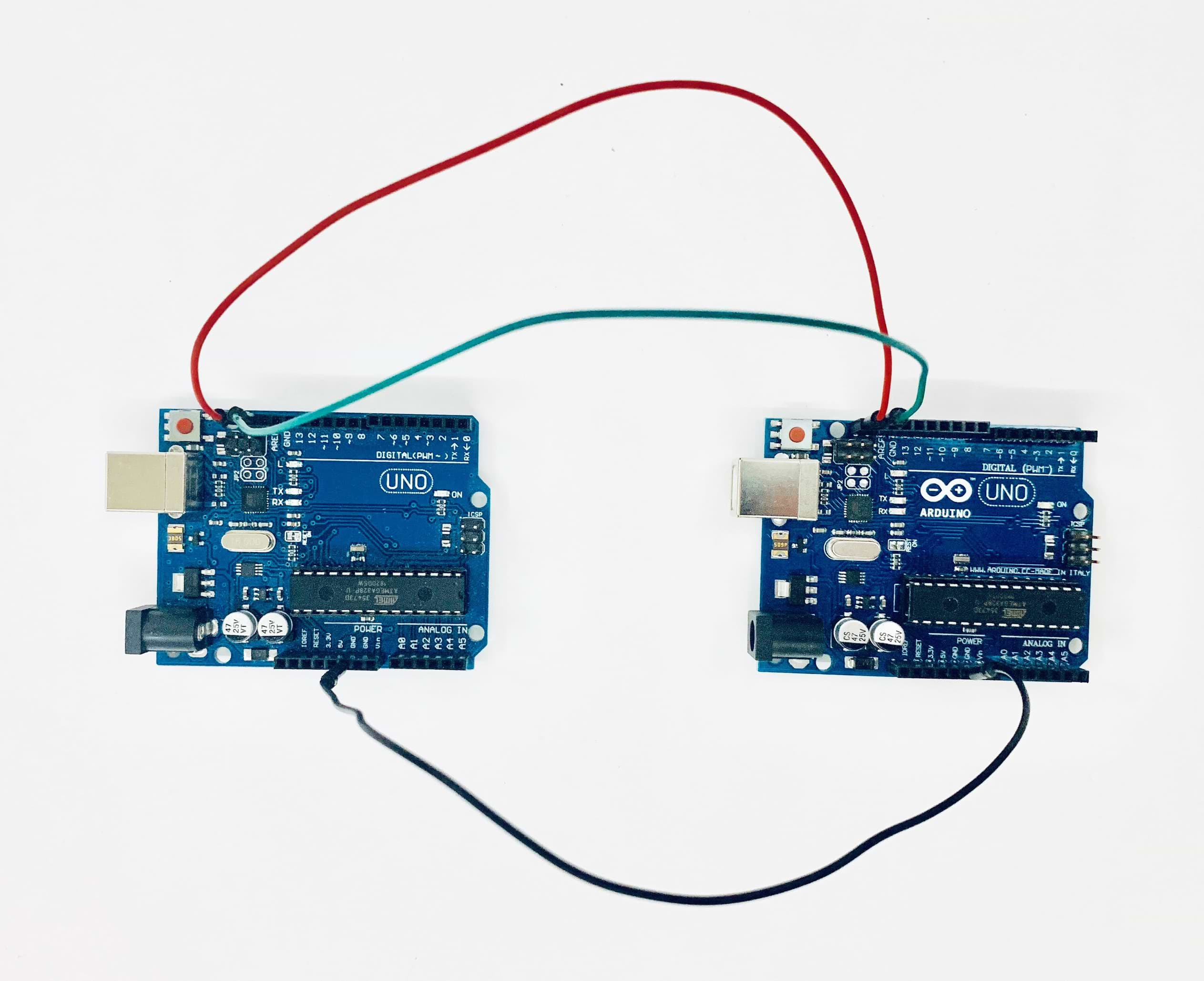
I’m going to connect the two Arduino boards as follow :
Programming :
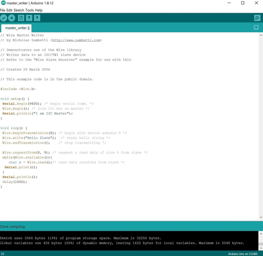
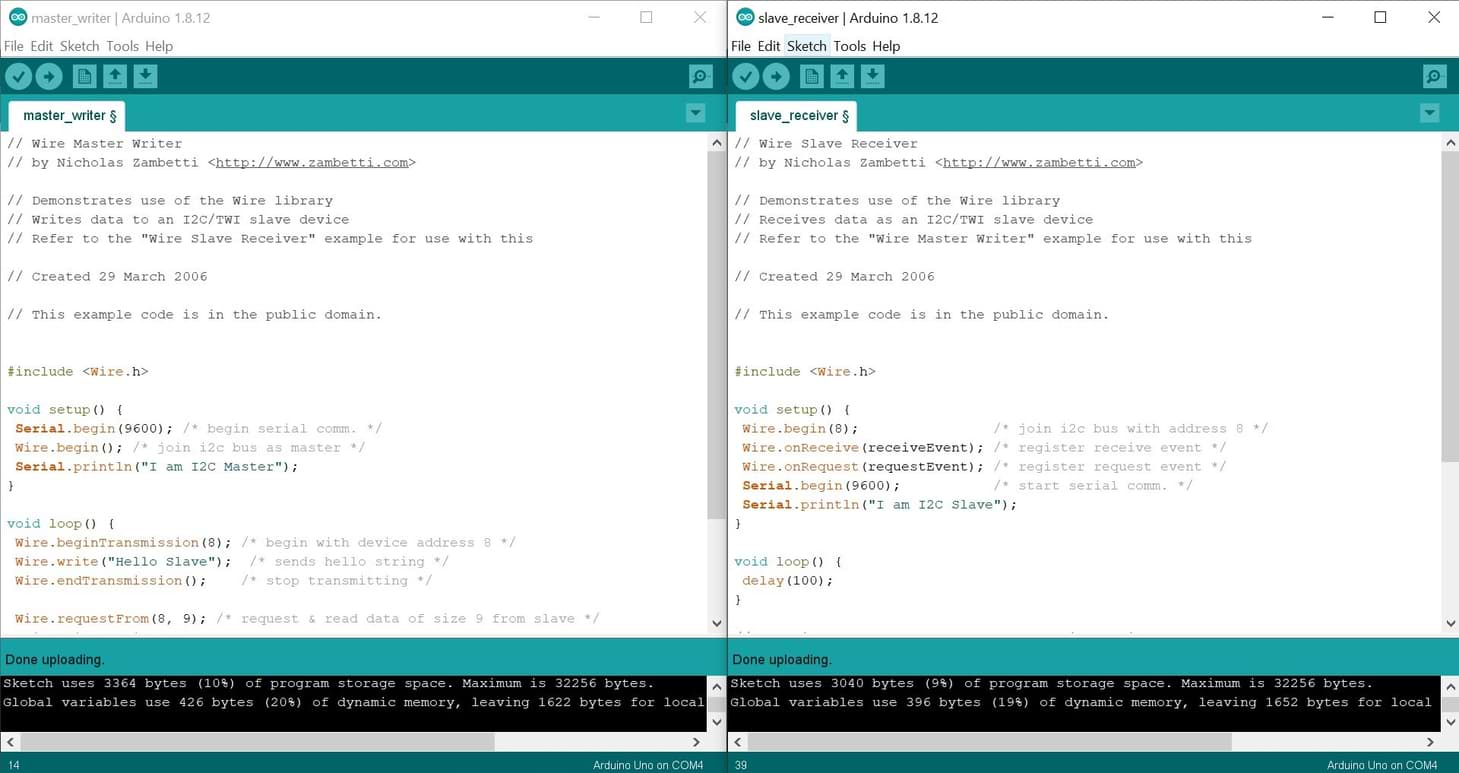
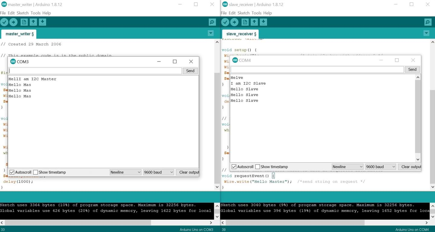
I’m going to program the two Arduino boards by sending a “Hello Slave” message from the master arduino to the slave and the slave will respond back to the received message with “Hello Master”.
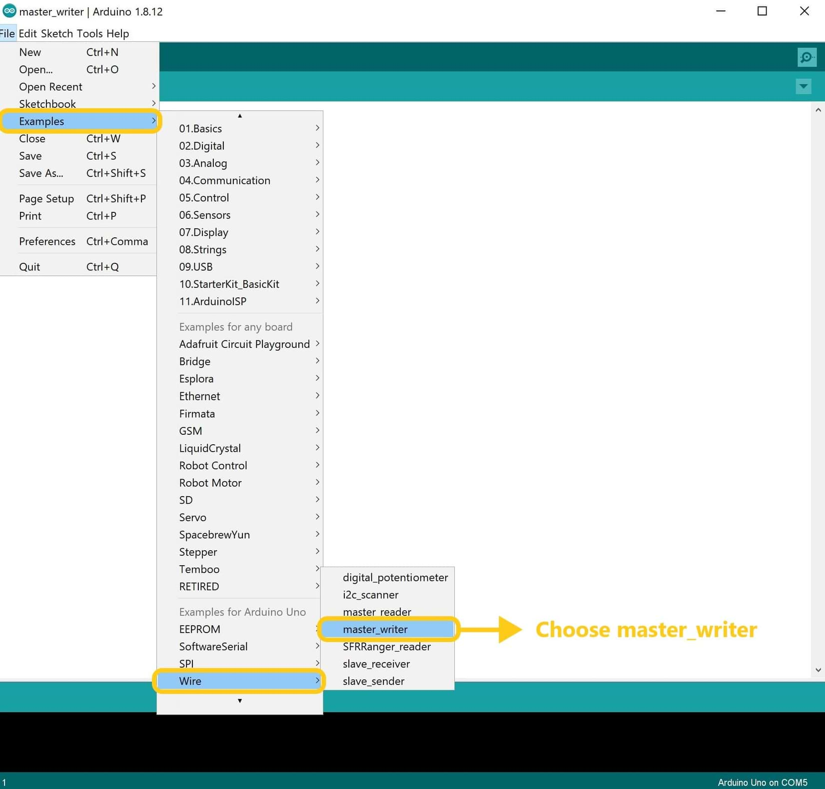
From Wire library, we are using master_writer for Arduino as master and slave_receiver for Arduino as a slave.
To program the master Arduino :
1. Open Arduino IDE page > Go to File > Example > Then choose master_writer.
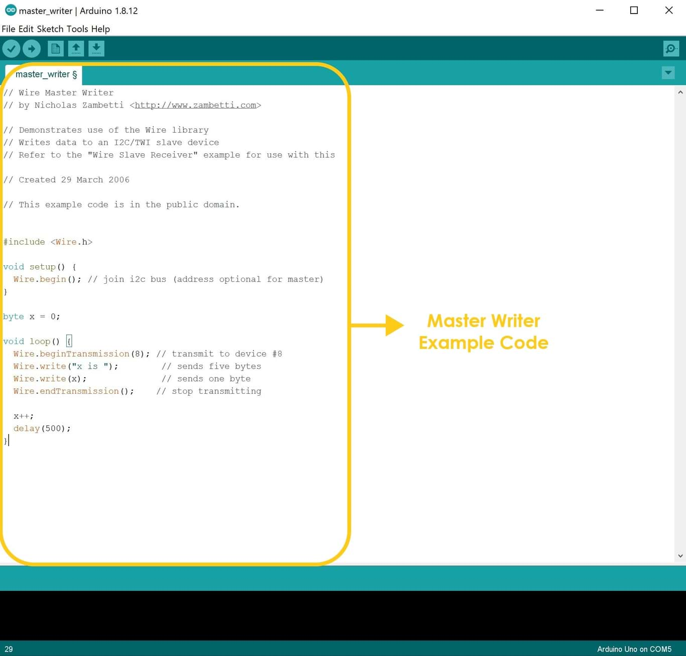
2. Write the following code in the code area.
3. Connect the USB to the computer port > Then go to tools and choose the port > Verify and upload the code.
4. Open the serial monitor to start the communication.
To program the slave Arduino :
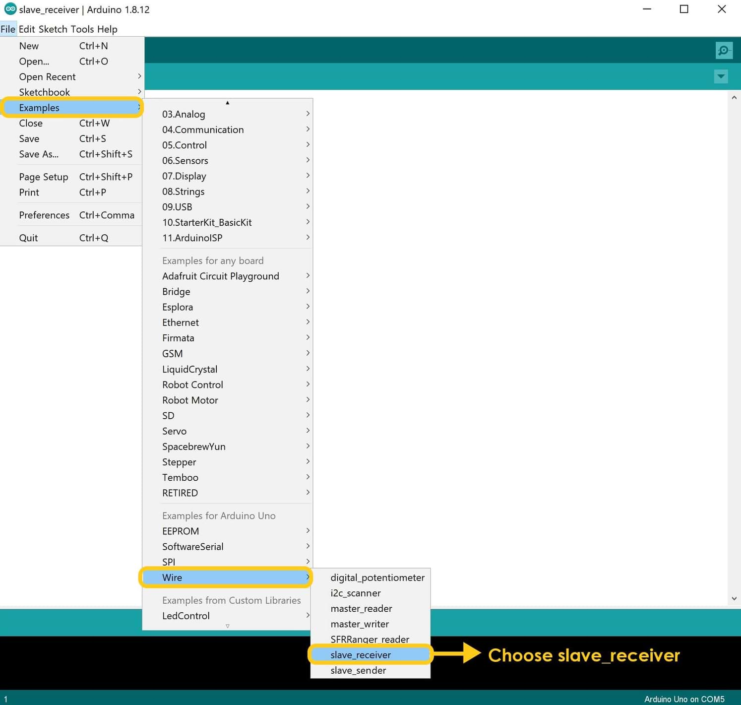
1. Open a new Arduino IDE page > Go to File > Example > Then choose slave_receiver.
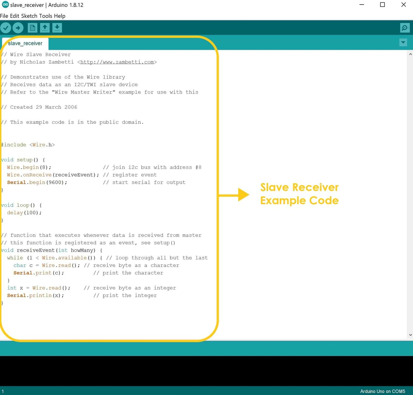
2. Write the following code in the code area.
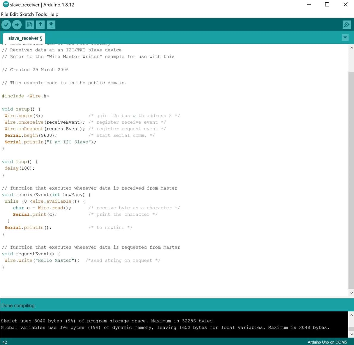
3. Connect the USB to the computer port > Then go to tools and choose the port > Verify and upload the code.
4. Open serial monitor to start the communication.
Let’s test the communication :
Now, I’m going to make another application by adding input and output devices. I will use the following:
In this application, the master arduino will send a sound to the slave arduino. And the LEDs in the slave arduino will detect the sound and turn ON. If the master arduino does not send a sound to the slave, the LEDs will keep OFF.
Wait !!! I did not explain the sound sensor in the previous assignments. So, I did some searches to know more about this output device. Let’s learn about it !
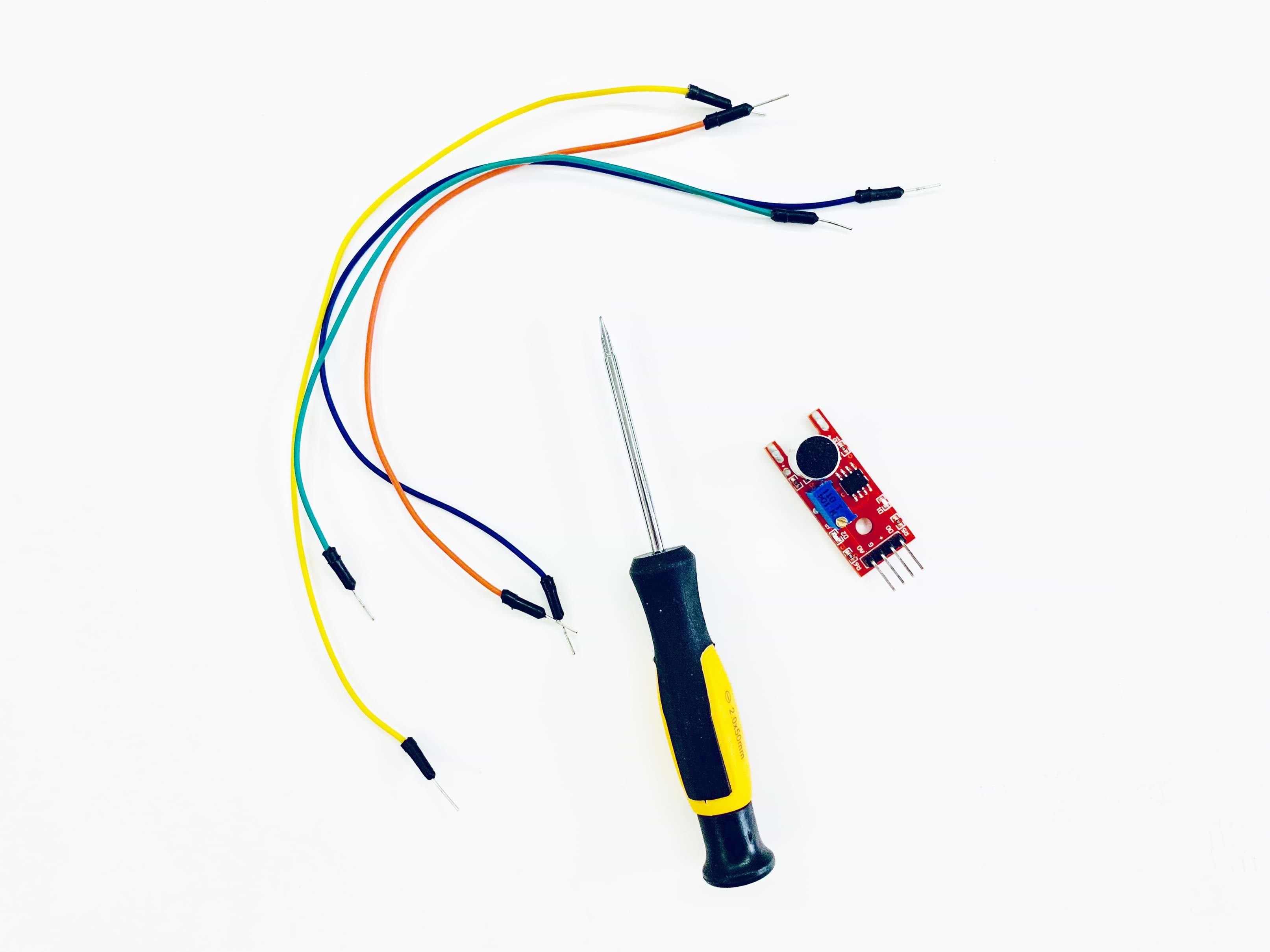
What is a sound sensor ?
The sound sensor is one type of module used to detect the intensity of sound. It has a built-in capacitive electret microphone which is highly sensitive to sound.
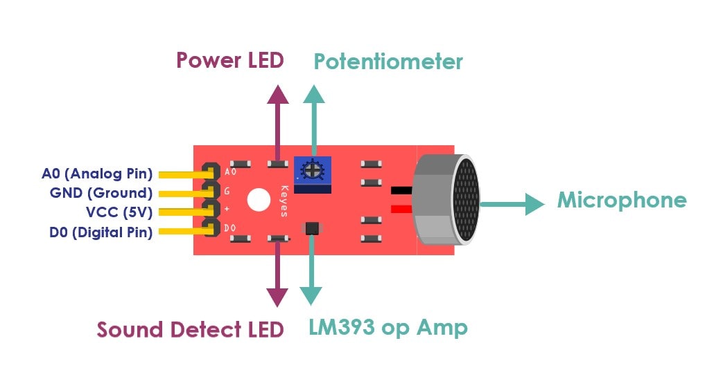
- CW = More Sensitive.
- CCW = Less Sensitive.
Let’s start !
In the test we will use the following componants:
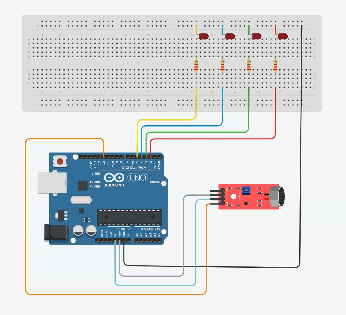
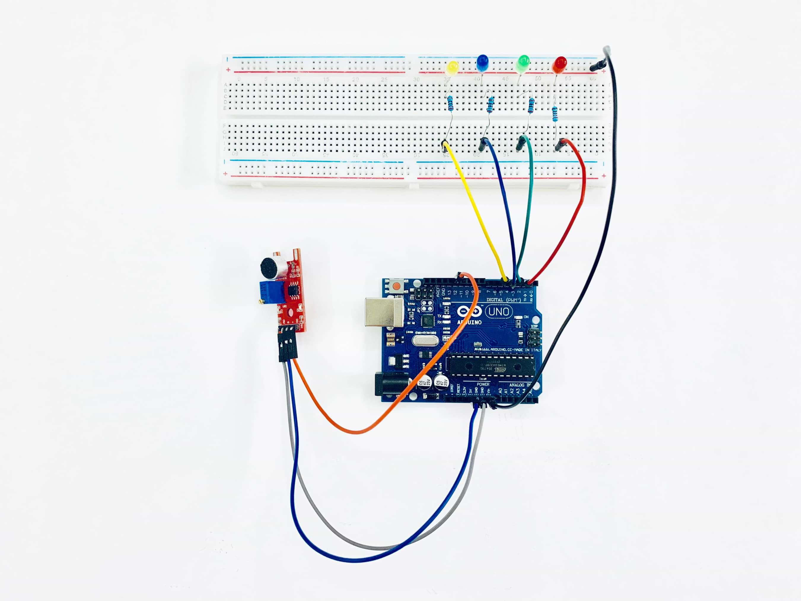
First, I’m going to connect the sound sensor and leds and upload the code in one Arduino board to make sure that it works
.The Connection :
The Programming :
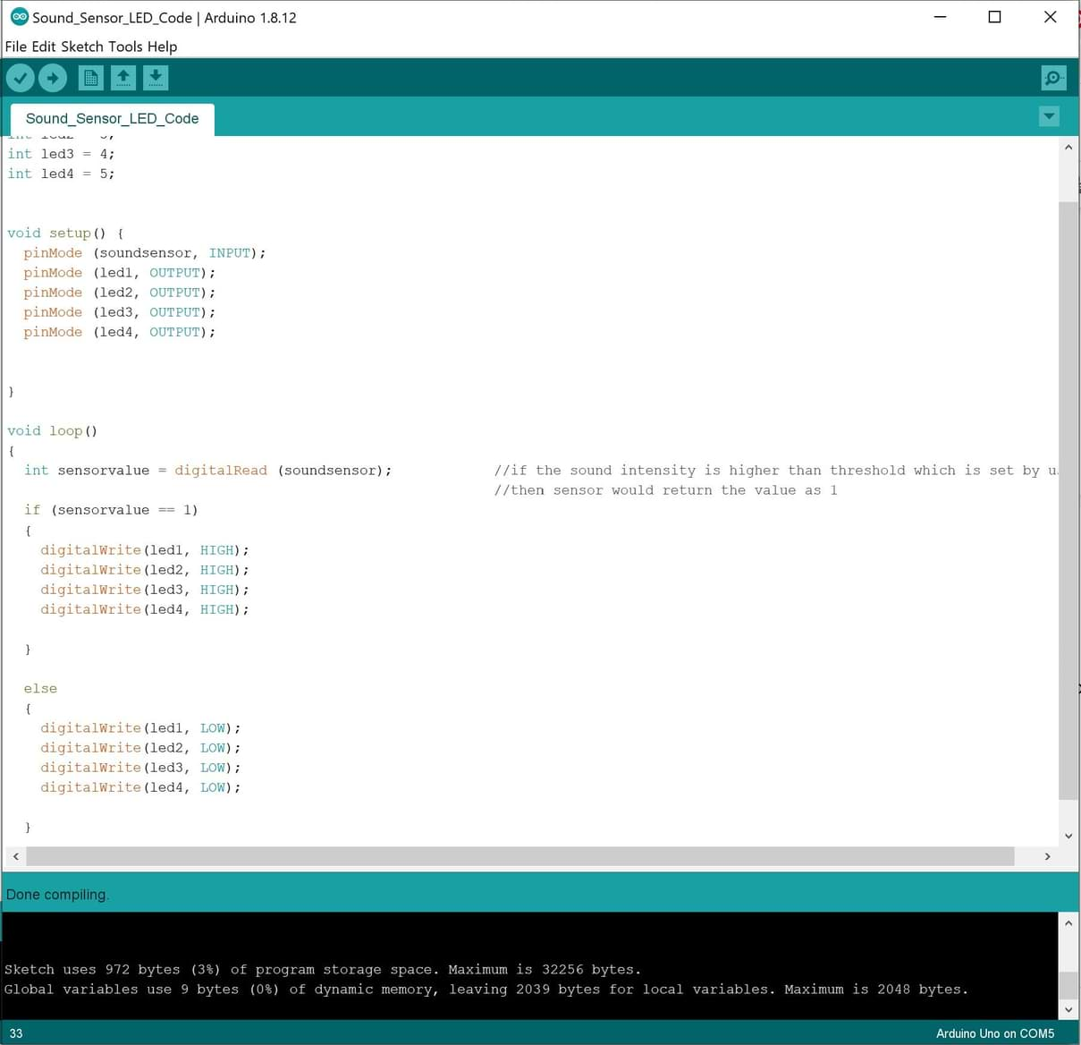
In this code, I’m going to do the following :
1. Defining the pin numbers void setup.
- int soundsensor = 12;
- int led1 = 2;
- int led2 = 3;
- int led3 = 4;
- int led4 = 5;
2. Defining the pinmood of the sound sensor and LEDs.
- pinMode (soundsensor, INPUT);
- pinMode (led1, OUTPUT);
- pinMode (led2, OUTPUT);
- pinMode (led3, OUTPUT);
- pinMode (led4, OUTPUT);
3. Defining the sound value. If the sound intensity is higher than threshold which is set by us, then the sensor would return the value as 1. The LEDs will turn ON if the (sensorvalue == 1), And they will turn Off if there is no sound.
I faced an issue while testing the sensor, the LEDs turned on all the time and they did not detect the sound. I searched about this problem and I noticed that the sound detector LED in the sensor is on, I have to change the direction of the potentiometer to change the sensitivity. I used a screwdriver to turn the direction of the screw until adjusting the sensitivity of the LED to detect the sound.
By the way, Today is a special day of Muslims. It’s Eid Al Fitr which is held to celebrate the end of fasting. It marks the end of Ramadan. So, I decided to play a song that related to this special event!!
It works!
Now, let’s connect two Arduino boards !
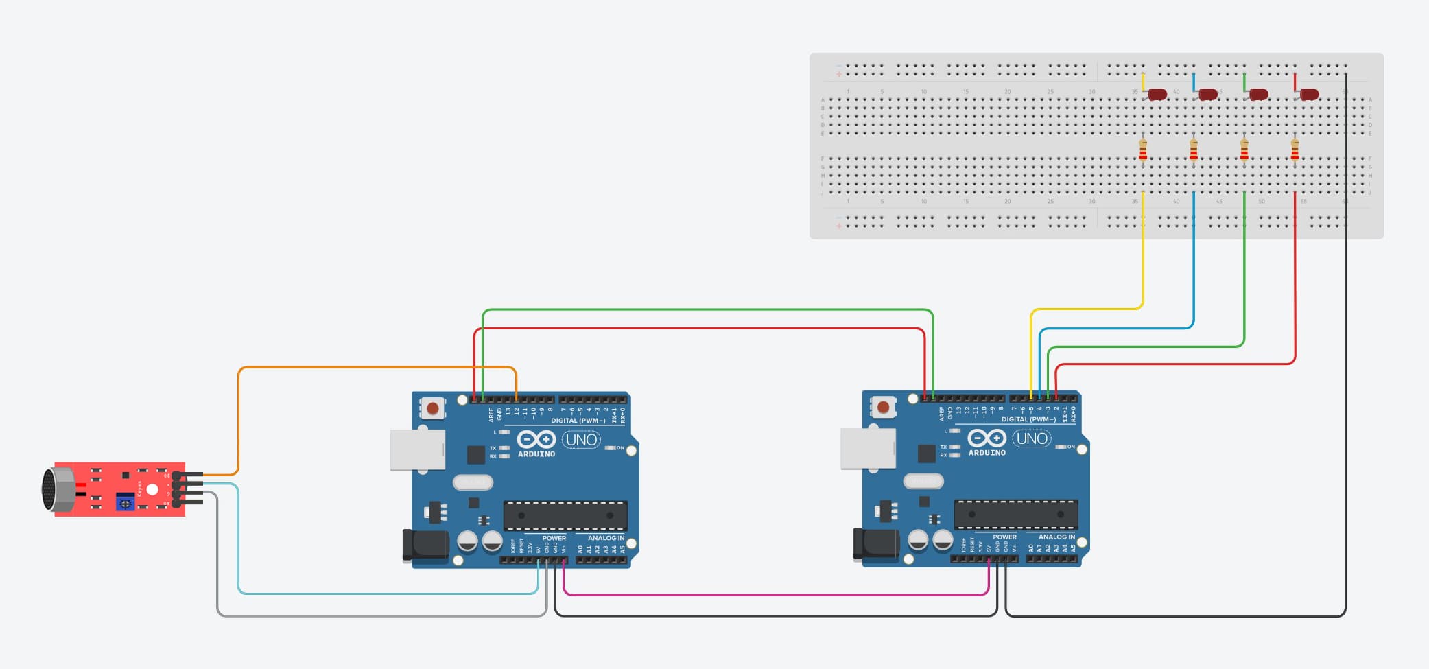
I’m going to use two Arduino boards to communicate with each other. The first Arduino will be the master which is connected with the sound sensor and the second Arduino will be the slave which is connected with the LEDs.
The connection :
Arduino Board (Master) will control the sound sensor.
To connect the sound Sensor Pins:
Arduino Board (Slave) will control the LEDs.
To connect the LEDs:
To connect the master Arduino to slave Arduino :
In my laptop, I have just one USB port. So, I couldn’t connect two USB ports at the same time to test the master and slave Arduino. To solve this problem, I used a VIN pin which is an input voltage to the Arduino board when it's using an external power source. I wired up the (vin pin) in the master Arduino to the (vcc pin) in the slave Arduino. Then, I connected one USB from the slave board to the laptop port. Now, (vin pin) supplies voltage to the master Arduino.
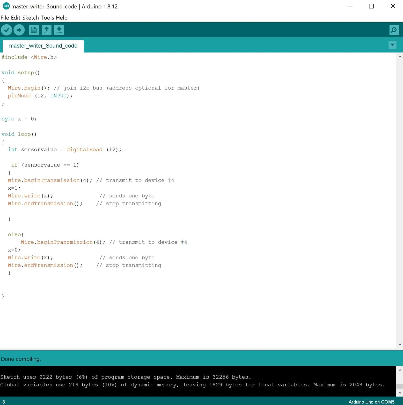
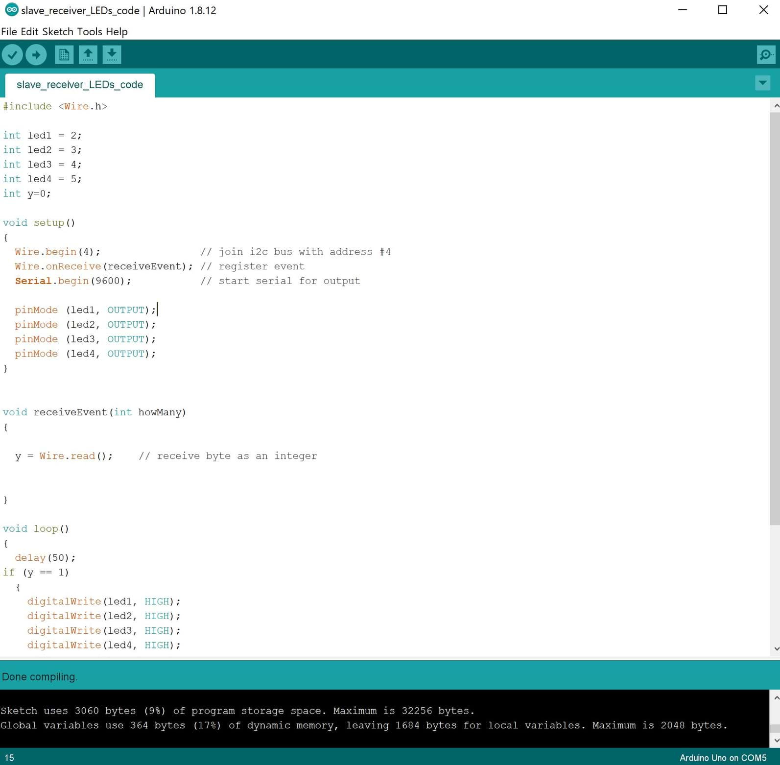
The Programming :
The Master Code :
The Slave Code :
Arduino Test :
PCB Test :
Due to COVID-19 lockdown, we did not have access to Talents lab to make the PCB until mid of July. Now, we finally got the access. I did many PCBs to use them in the electronics assignments and final project.
In this assignment, I have to use two PCBs to make the communication. I used 328p microcontroller.
To see the design and fabrication process of the boards you can check the following assignments :
Programming :
After finishing welding the PCBs, I started working on the connection to upload the code. First, I uploaded ArduinoISP to my Arduino then I connected the ISP wires to upload the code to the Master PCB then Slave PCB. I connected the sound sensor with the master board and LEDs with Slave PCB. I used wire.h library to implement I2C protocol between master and slave boards.
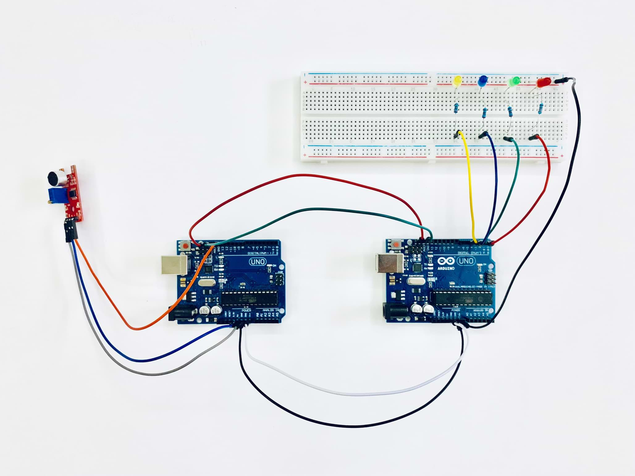
After uploading the code successfully. I started connecting the two boards with each other.
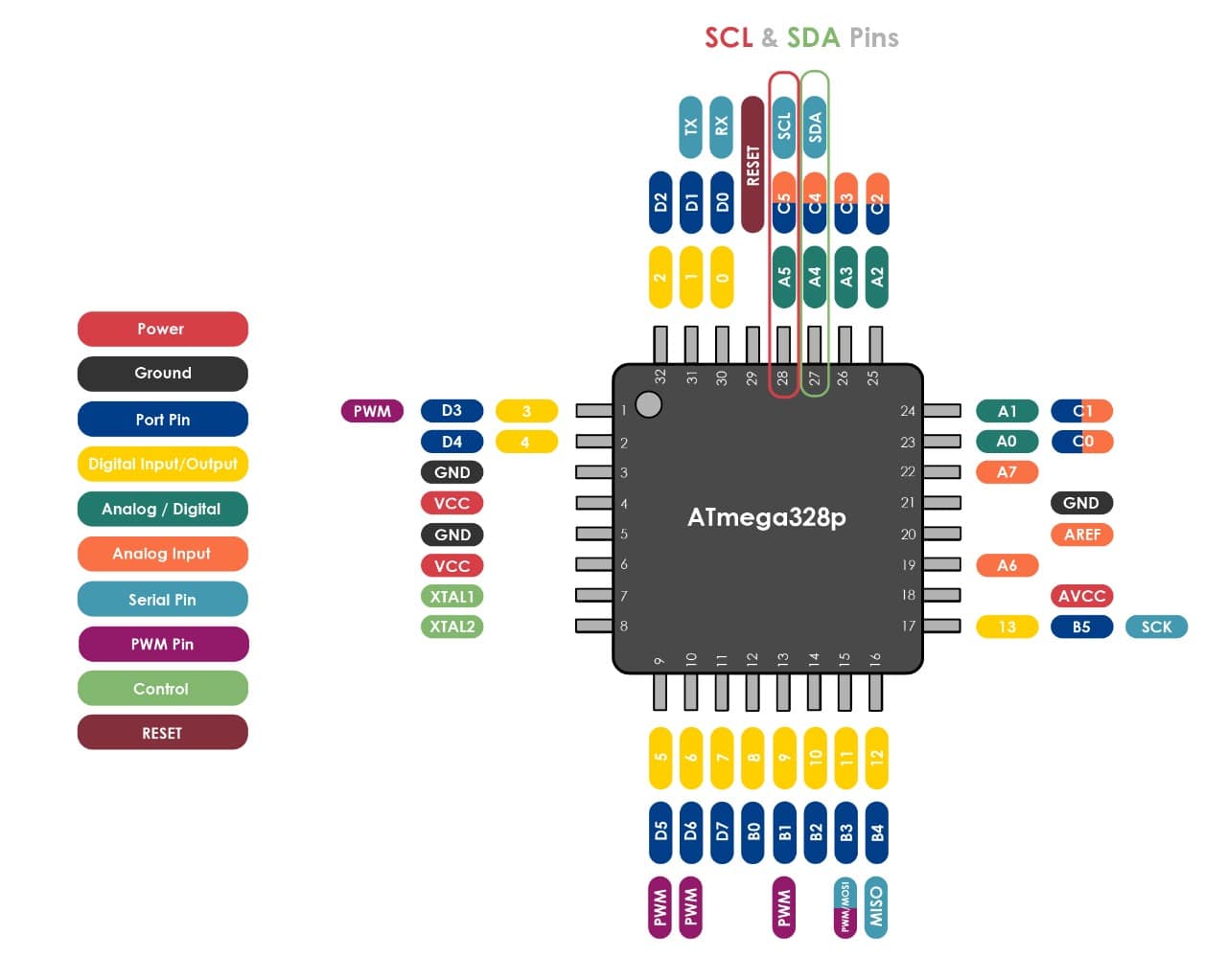
To connect the boards we need to connect 3 main pins ( SDA, SCL and GND ) to enable I2C communication. I checked the Atmega328p microcontroller diagram as shown in the photo below to find SDA and SCL pins location.
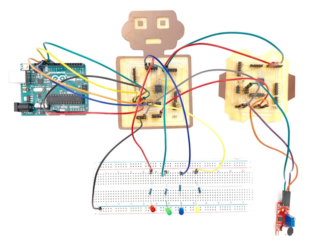
I connected the wires between the boards as follow :
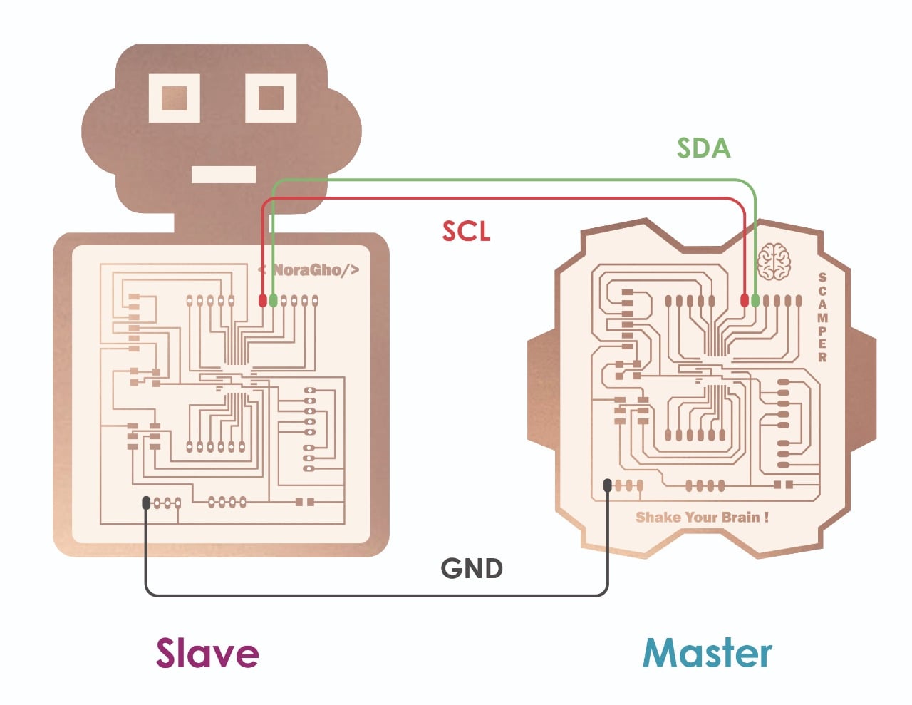
I connected the Slave board with Arduino to get power 5V pin and GND pin. Then, I connected the Arduino USB cable to the laptop. Also, I connected 5V in the Master board to 5V in the Slave board to power it up after powering the slave.
Finally ! It works !!!