Fianl Project
FINALLY !!! It is the last last last documentation!! I can not believe that !! It is the FINAL PROJECT !! Time to GRADUATE Wahooo !
One of the main requirements in FAB Academy is to make a final project and present it to Prof. Nail. I am going to talk about my final project in detail starting from the idea until the final product. It is an amazing journey. I hope that you like the final result.
Are You Excited?
YES, نعم, OUI, はい, SI
All people around the world should be excited at this moment =) !
Let’s Start!
Shake Your Brain !
Concept
With the use of the golden circle, I will be using three simple questions to represent the idea of my final project.
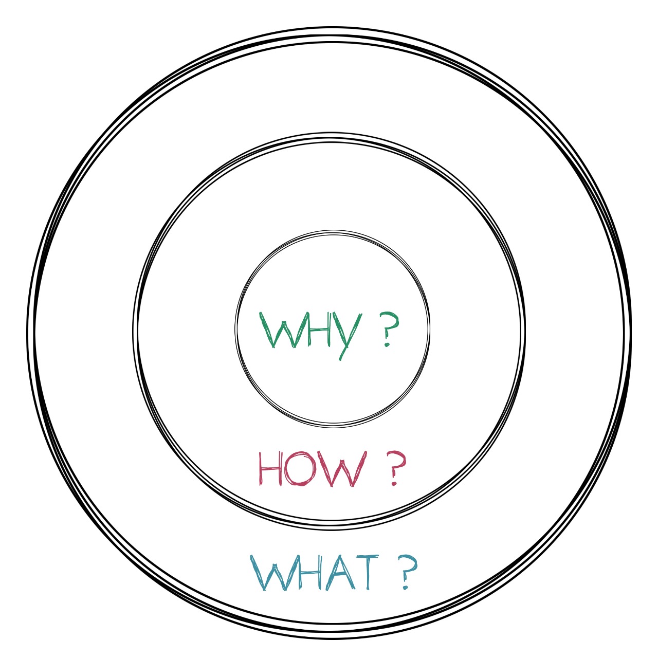
Why?
I am working for National TalentS Company which operates many learning programs and FABLABs. I have been working as an operation manager and technical expert in many different learning projects . We usually have short periods in such learning programs, and we have always faced a problem or the other when we are trying to get ideas to make different prototypes from the students during the program.
How?
To solve this problem I designed a kit to make this stage of the programs more fun for the students by playing and thinking at the same time to generate the ideas faster !
Also, I faced the same problem while working on FAB Academy assignments and final project. It’s so hard to start the assignment with a unique and creative idea.
What?
If you’re trying to create something new, or just trying to improve a design, it’s all about asking the right questions. Sometimes it can be hard to find new ideas or you might find yourself stuck on a new assignment. In these cases it’s really helpful to have some methods, or guidelines, to help you out, and get the creativity started again!
For the final project, I decided to make a kit/device called Shake Your Brain!
What is Shake Your Brain ?
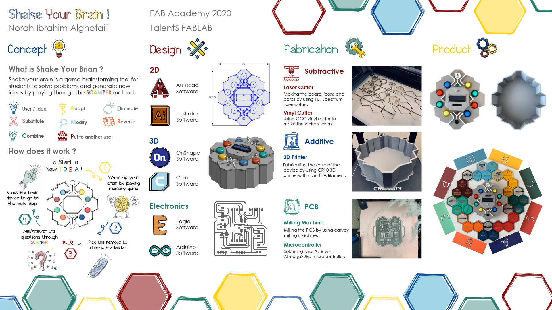
It is a game, a brainstorming tool for students to solve problems and generate new ideas by playing through the SCAMPER method.
Have you ever heard about the SCAMPER method?
SCAMPER is a creative, easy-to-use brainstorming technique that helps generate new ideas or improve existing ones.
The SCAMPER method has 7 phases:
S = Substitute: To think about substituting part(s) of your product or process for something else.
C = Combine: How can you combine two or more parts of your product, problem, or process so as to achieve a different product, problem, or process to enhance synergy.
A = Adapt: What can I adapt to my product, problem, or process? Think about which parts of the product or process you could adapt so as to solve your problem.
M = Modify: Think about changing part or all of the current situation or product. Alternatively, distort the product in an unusual way.
P = Put to Another Use: It’s time to work out how you may be able to put your current product or idea to other uses and purposes.
E = Eliminate: Think of what might happen if you were to eliminate, simplify, reduce, or minimise z parts of your idea.
R = Reverse: How can I change, reorder, or reverse the product or problem? What would I do if I had to do this process in reverse?
How does the project work?
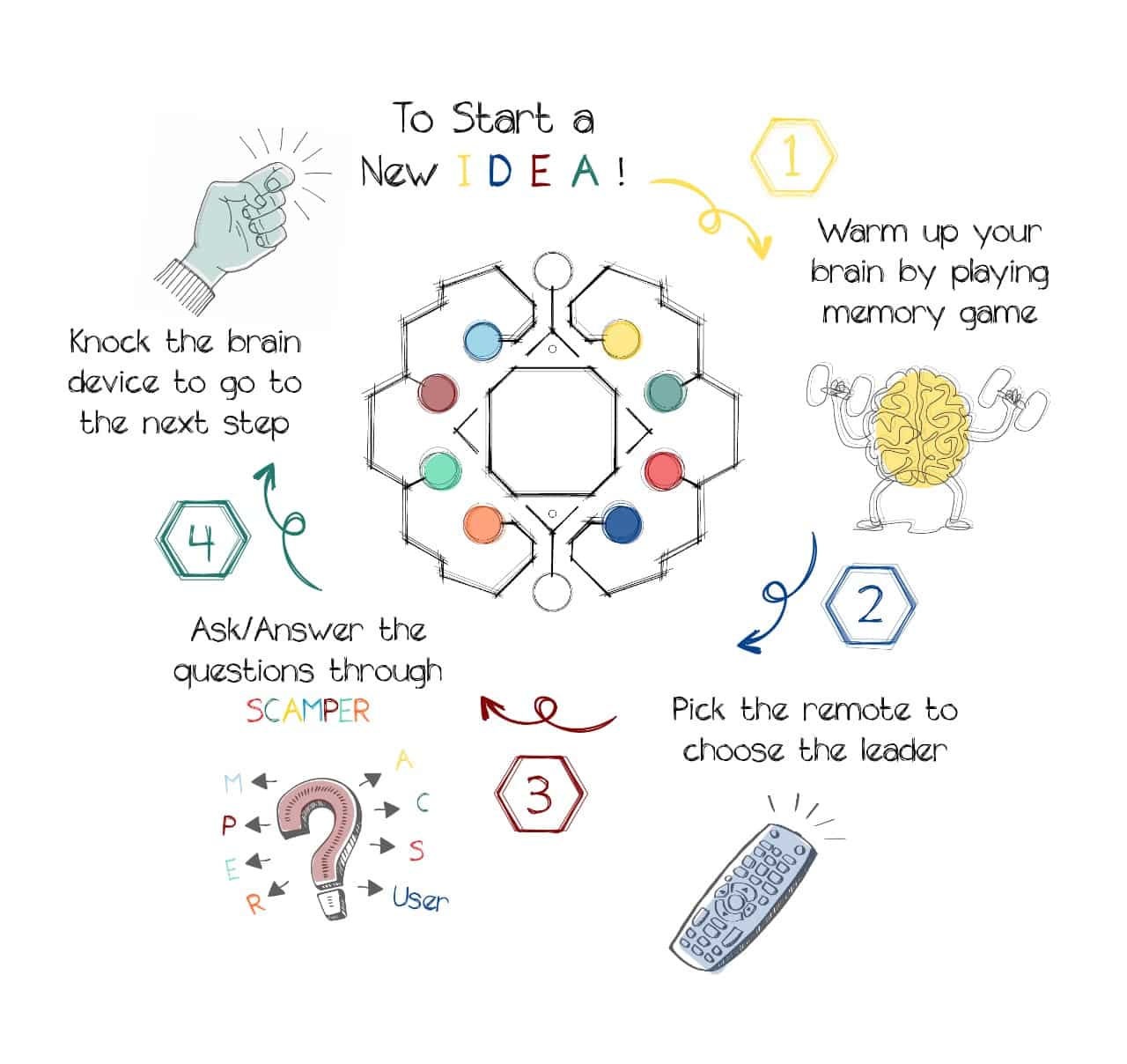
The students will start the journey with the following steps :
1. Warm-up your brain:
Warming up the brain improves learning ability, and the attention span improves. In this stage, the student will play a “Memory Game” and the timer will start for 10 minuits.
2. Pick up the remote to select the leader:
Now, The students will use the remote control and select any number randomly. The student who chooses the right number will be the leader who guides the round by asking the questions and sketching the ideas.
3. Choose a product and user:
After selecting the leader, the students will choose an existing product, service or idea they want to improve or which could be a great starting point for future development. Also, they will identify the user who will use this product.
4. Starting SCAMPER method:
At this stage, the leader will start the first round by using different cards and asking serial questions that help students to analyze and dig deeper with problem-solving. The students/players will answer the questions by sketching or writing on the cards; then, they build them together to finalize the idea. Each round will have a different leader.
5. Knock the brain:
The students will knock the brain device once they finish the round to go to the next step.
The User Guide:
MAKE The Final Project:
To MAKE the final project, we were asked to incorporate 2D and 3D designs, additive and subtractive fabrication processes, electronics design and production, embedded microcontroller interfacing and programming, system integration, and packaging.
Let’s MAKE It!
2D Design
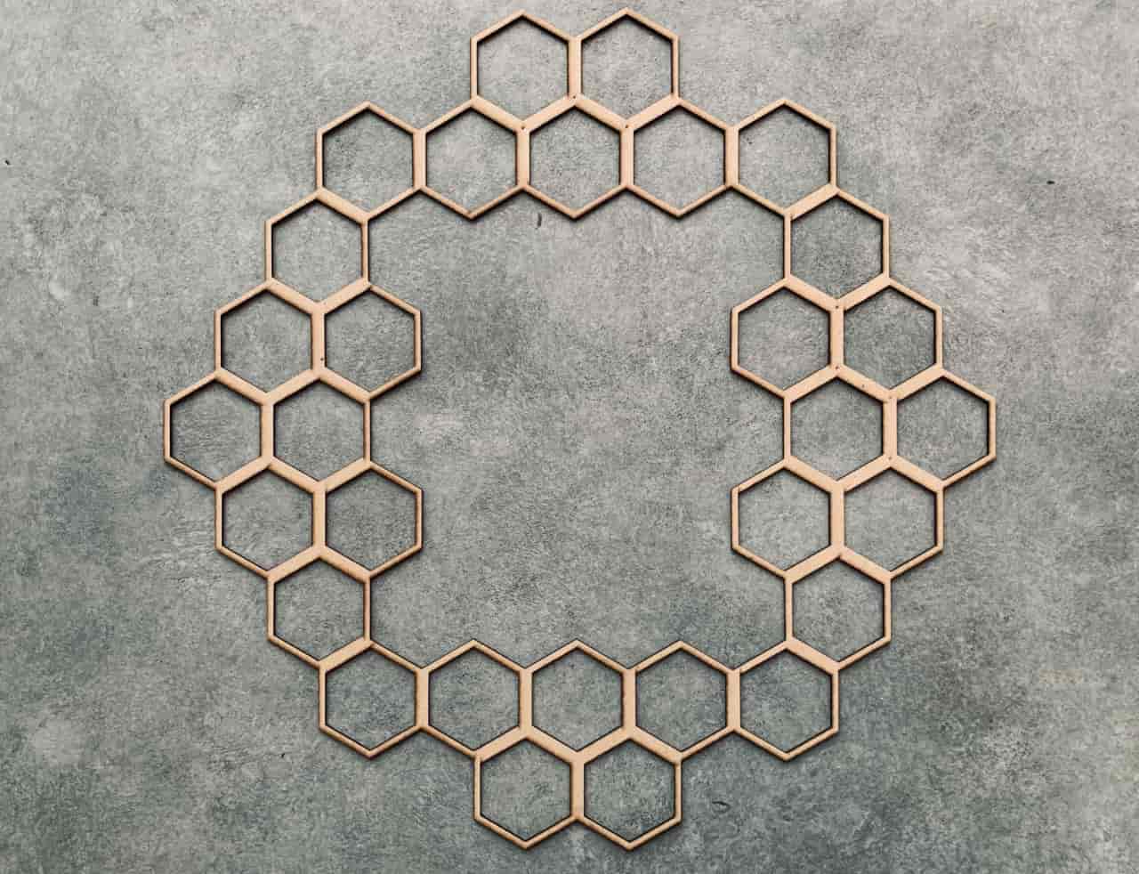
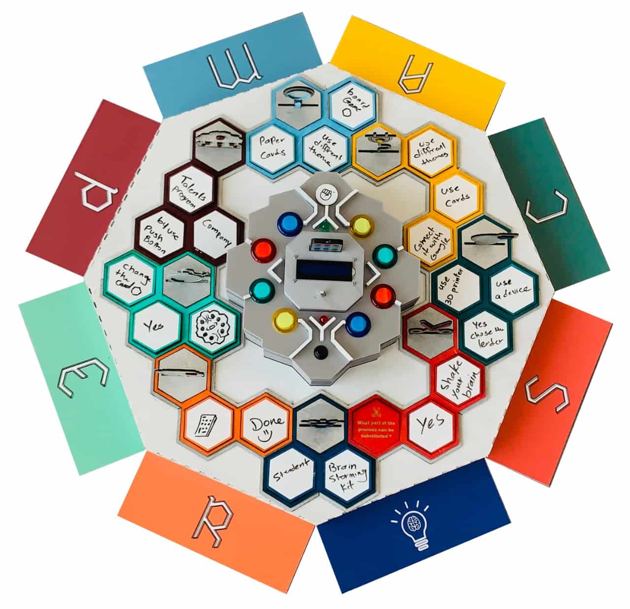
In the 2D part I am going to design a board game that allows the students to sit around and play. Also, I will design the cards that contain all the questions. I am going to use Autocad software to design them. I decided to make the shape of the board polygon with 8 sides. Each side will express one round of the game. Also, I decided to put the device in the center of the board, and the cards will be around it.
Design the board sheet:
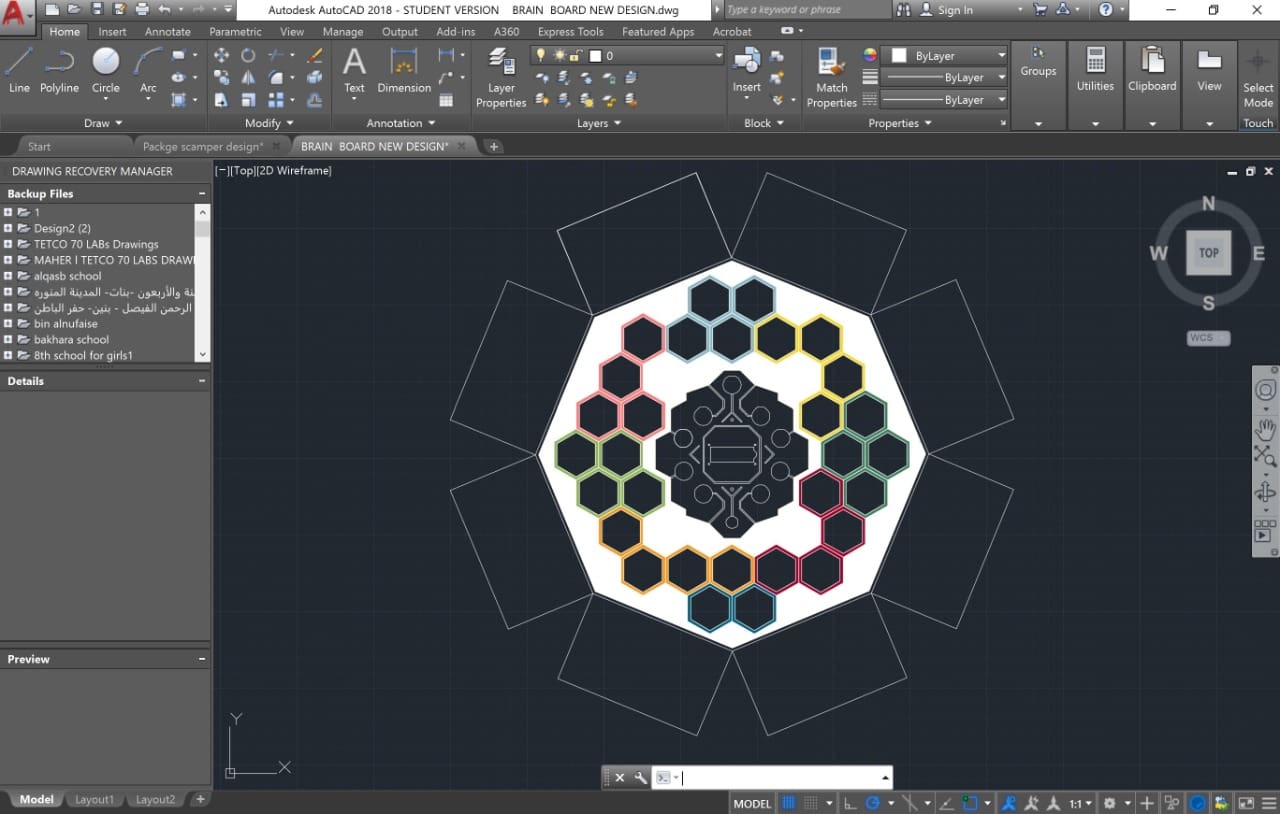
I used Illustrator software to design the bottom part of the board which is the board sheet. This design expresses the messy ideas in the brain. Also, it contains the letters of the SCAMPER on each side. The students will put the cards on the sides at the beginning of the game.
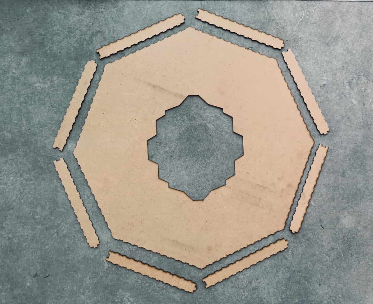
Design the polygon box:
To design the game board, I did the following:
1. Open Autocad software > draw a polygon with 8 sides > Then make a joint to be a polygon box.
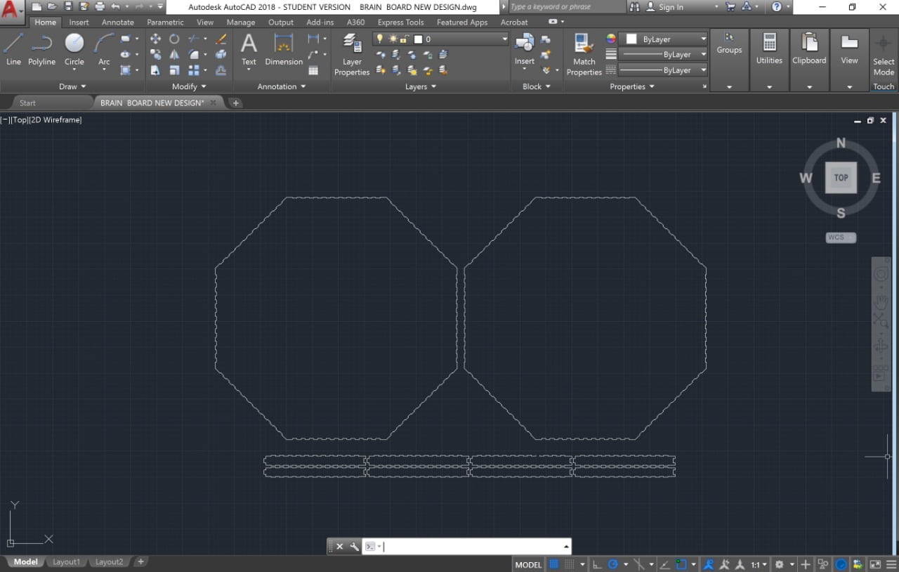
2. Draw the outline shape of the device.
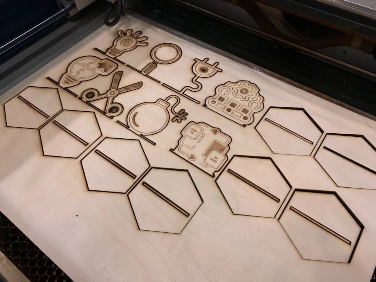
3. Draw the cards shape and write the text.
Subtractive Fabrication
Laser Cutter :
It is time to fabricate the designs. I used a full spectrum laser cutter to cut the game board and cards by using wood material.
Vinyl Cutter :
I used a whiteboard sticker to allow the students to draw their sketches and erase it at any time.
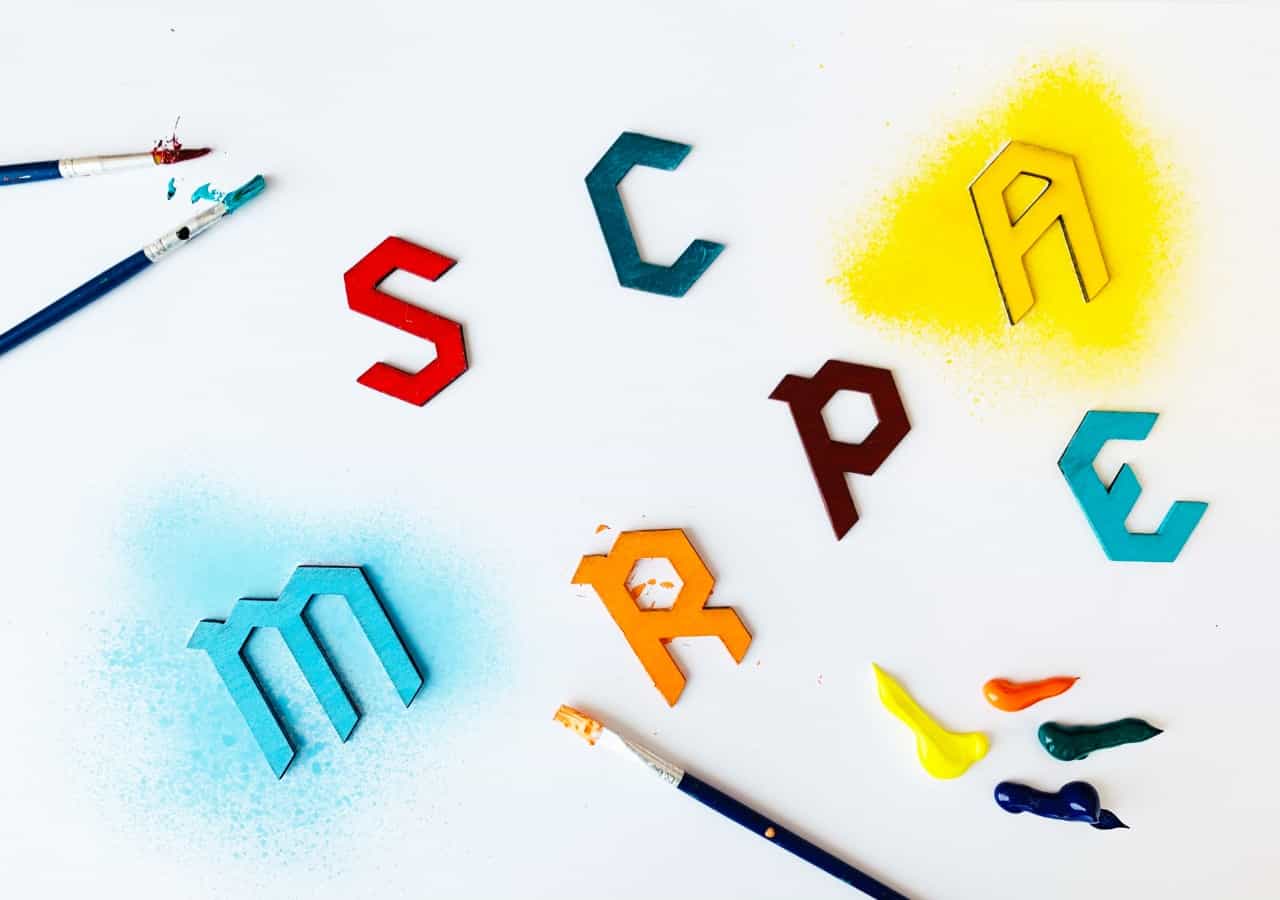
Finishing :
I used colors and spray to do some touches to make the final result of the project perfect. I decided to make each round with a different color to show the players the different stages of the game.
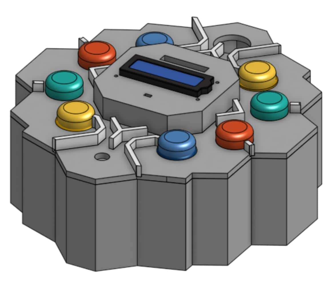
3D Design
In the 3D design, I am going to design the device as a 3D object by using OnShape software. To design the device, I got the inspiration from the shape of the brain. The device will contain 3 parts:
Before I started the design, I took the measurements of all the electronic components that I am going to use in the device to make sure that all the components will be fit in the device.
Now, I am going to design the object :
1. Open a new sketch > Draw the shape by using a line > Then extrude the shape with thickness = 8 cm.
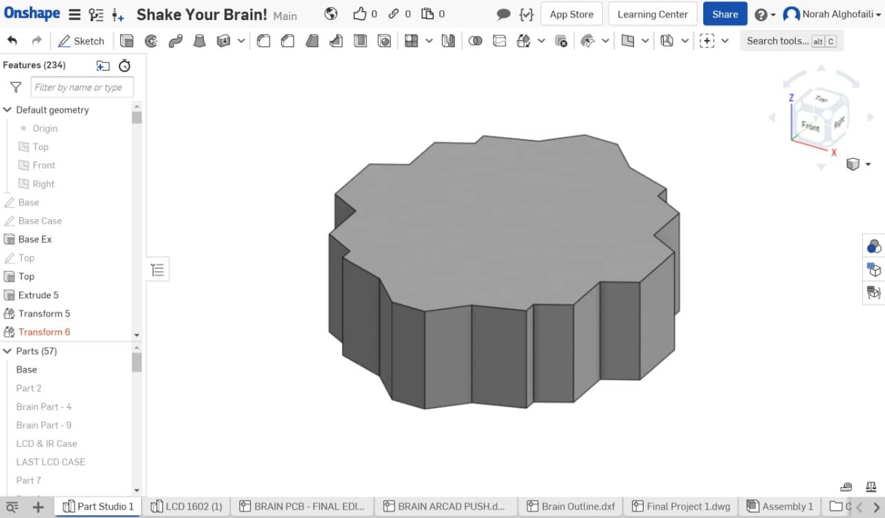
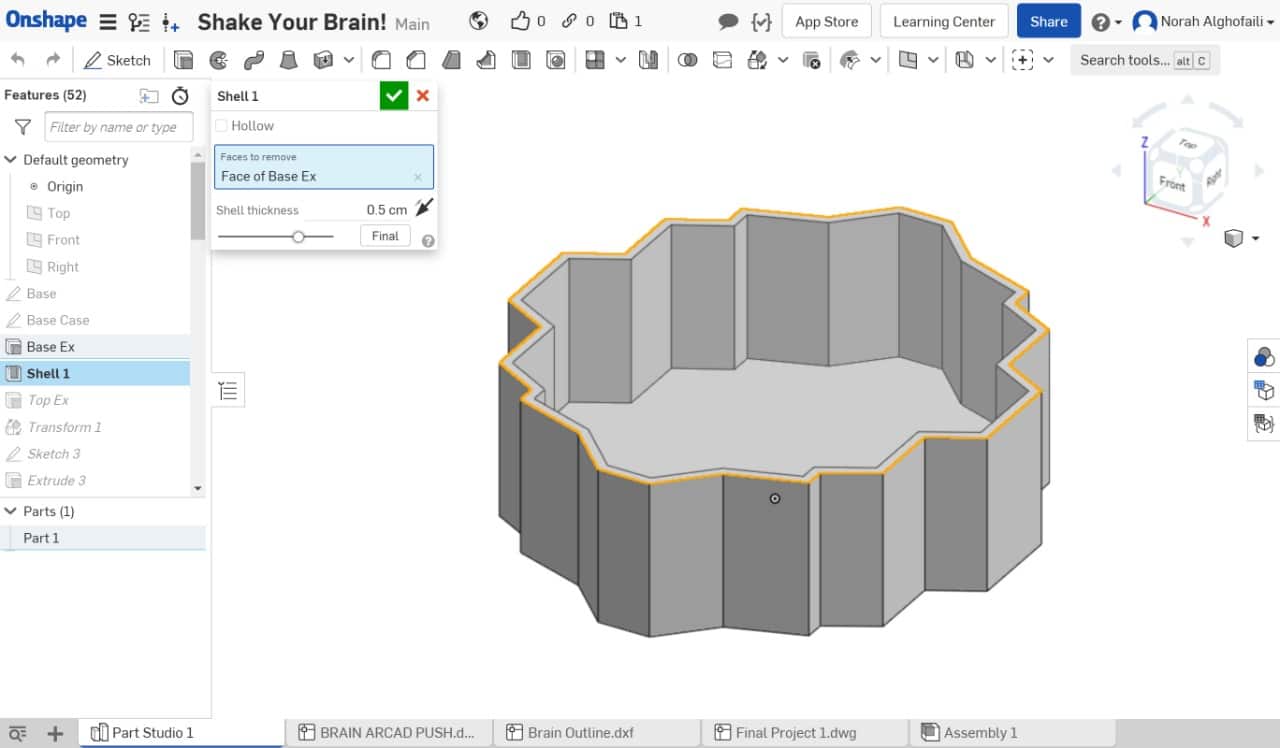
2. Select the object > Go to shell > Make the shell thickness 0.5 cm.
3. Now start a new sketch to draw the top part.
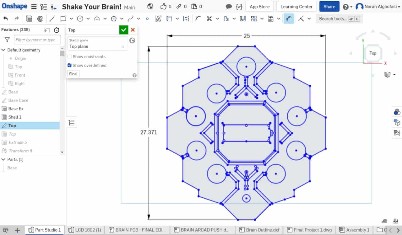
4. Then extrude the top shape with thickness = 0.5 cm.
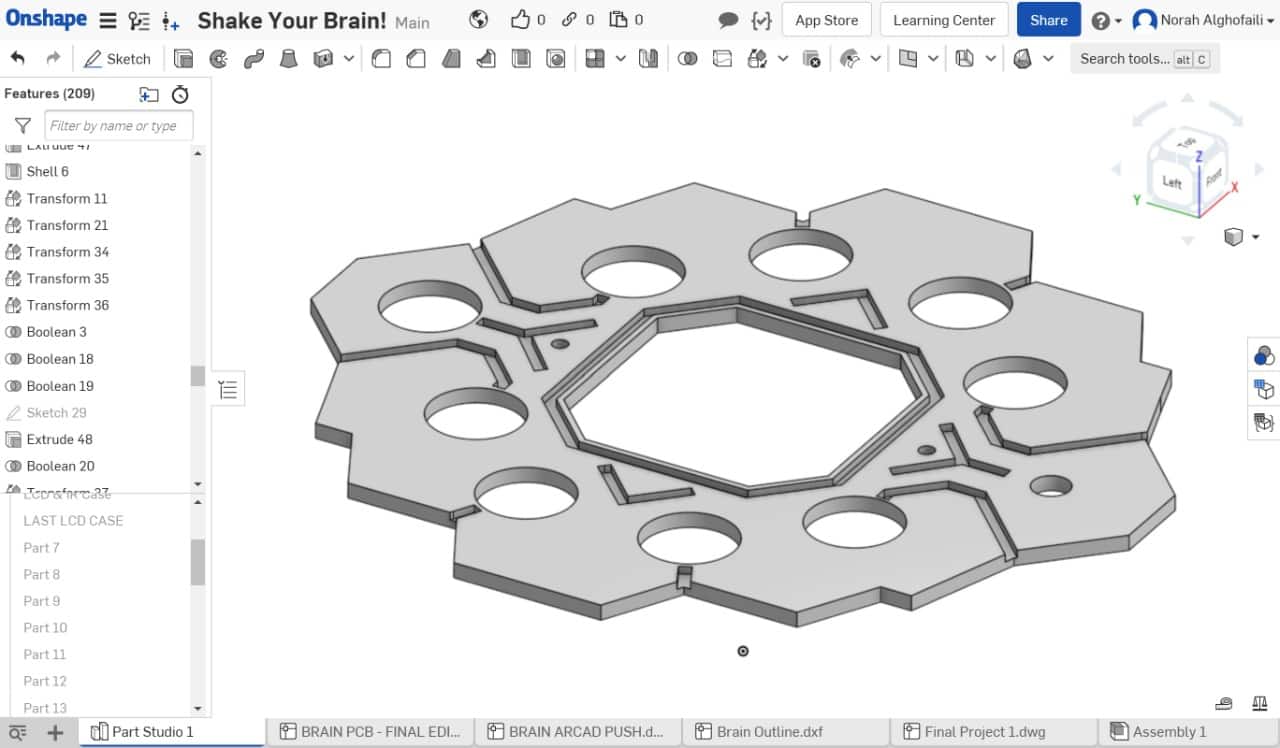
5. Now start a new sketch to draw the LCD case.
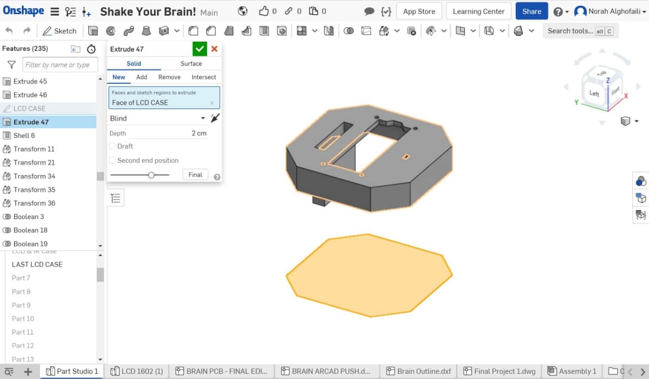
This is the final result of the device.
Now, I am going to export all the design parts as STL files to print them.
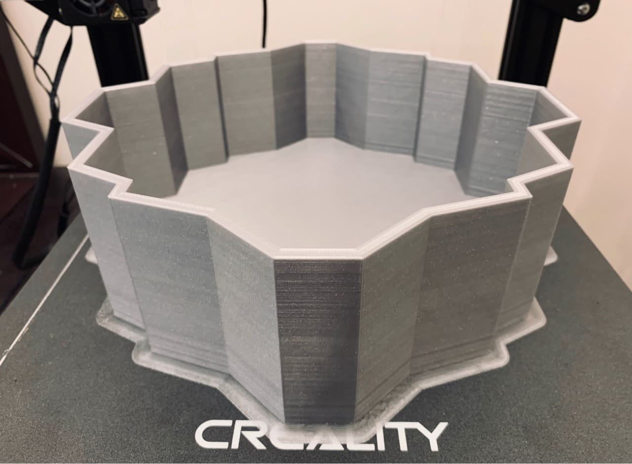
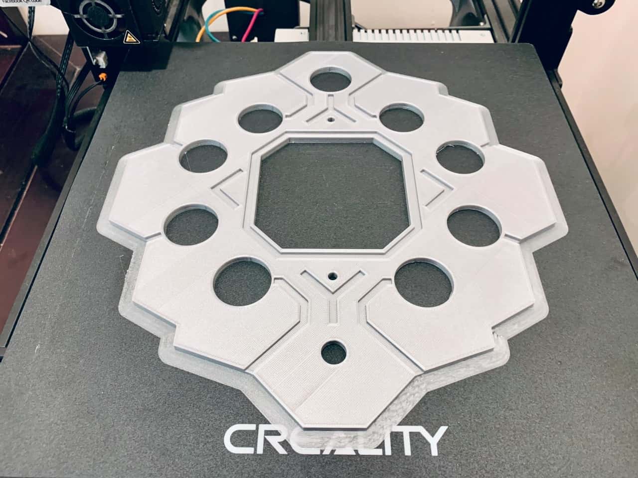
Additive Fabrication
Time to use the 3D printer! In this project, the object dimensions are too big 27 x 25 cm. So, I could not use the Prusa 3D printer to print it. I am going to use a CR10 3D printer. This printer has a plate with dimensions ( 30×30×40 cm ).
To print the design in CR10, I have to import the STL files to Cura software.In the LCD case part, I put support density = 5 for the remote part.
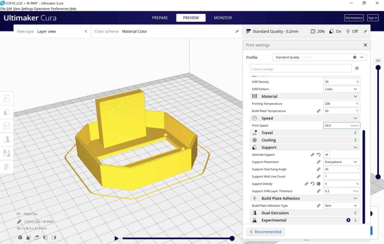
Then, I removed the support part by using a pliers tool.
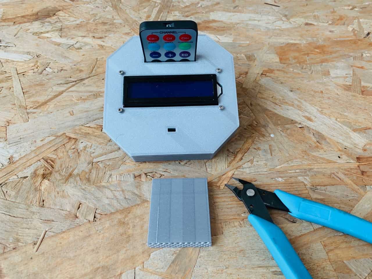
The bottom part object will take 34 hours to print!! wow.
The top part:
Electronics:
Electronics Design
In the electronics part, I am going to explain the process of designing my final PCB and all the electronic components that I decided to use to make the system.
Before designing the PCB, I have to list the number of input and output devices that I expected to use in my project to know exactly how many pins that I need to use.
The input and output devices that are needed in this project are:
Input devices :
Output devices:
Input and output ( LEDs & Pushbuttons ):
8 Arcade Push Buttons: 16 pins, 8 GND , 8 VCC.
So, the total pins that we need are:
Designing the PCB:
I used eagle software to design my microcontroller board, and I decided to use Atmega 328p as I have a significant number of inputs and outputs.
What is ATMEGA328P microcontroller?
ATMega328P Microcontroller is a high performance, low power controller from Microchip.
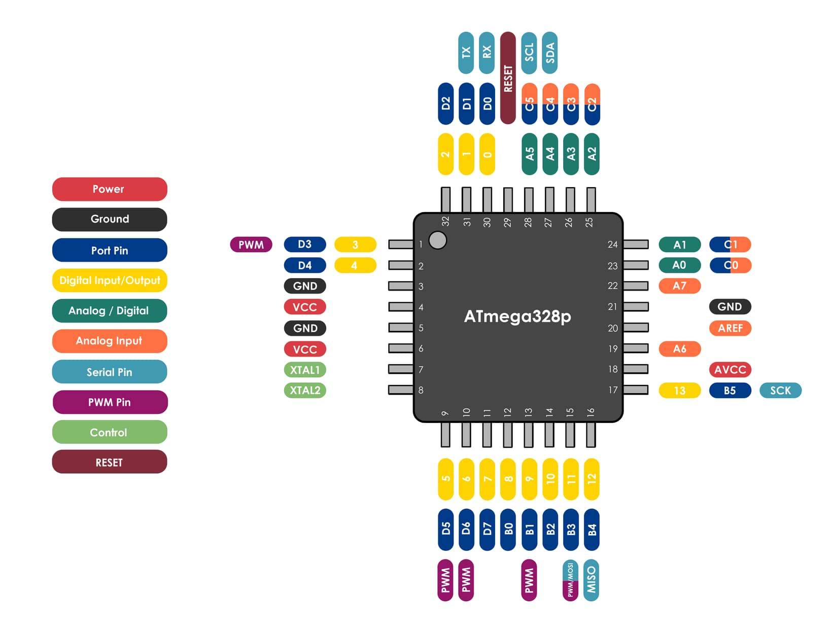
I read the datasheet of this microcontroller, and I noticed that ATMEGA328P has 18 pins, as we can see in the above sketch. So, it is not enough. I asked my instructor what I should do in this case. He advised me to make two boards; then, we will make communication between them by sending high and low voltage levels. (The ground was common between two boards).
Eagle Software:
To know more about Eagle software, take a look at Design Assignment.
In the schematic window, we have to insert all the required components, then label and organize them. The components that I am going to insert are :
Microcontroller
The 3 main components required with ATMEGA328P to allow us to upload the code are:
Headers for:
Board Window
After finishing the schematic design I clicked on the board icon to move into the board window and then started organizing and connecting the components together with no intersections using wires icon.
After finishing the drawing, I exported it as an image. Then, I am going to import it in Inkscape to trace the image and design an outline for the PCB.

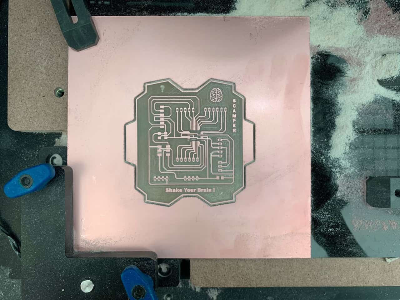
Milling the PCB:
Easel software:
Now, I am going to import the PCB drawing to the easel software to mill and cut the PCB.
Trace:
Milling Settings:
Bit : 1/64 in = 0.015 in, but I prefer 0.012 in
Depth : 0.2 mm
Depth per pass : 0.1 mm
Dots
Dots Cutting Settings :
Bit : 0.016 in
Depth = 1.8 mm
Depth per pass = 0.3 mm
Outline
Outline Cutting Settings:
Bit : 1/32 in = 0.031 in
Depth : 1.8 mm
Depth per pass : 0.3 mm
After doing the setting, I clicked on Carvey to start mill the board. This is the hardest part because we have a short time, and milling the boards takes a lot of time.
The bits that I am going to use are:
This is the milling bit:
The cutting bit:
Now, Start Carvy !
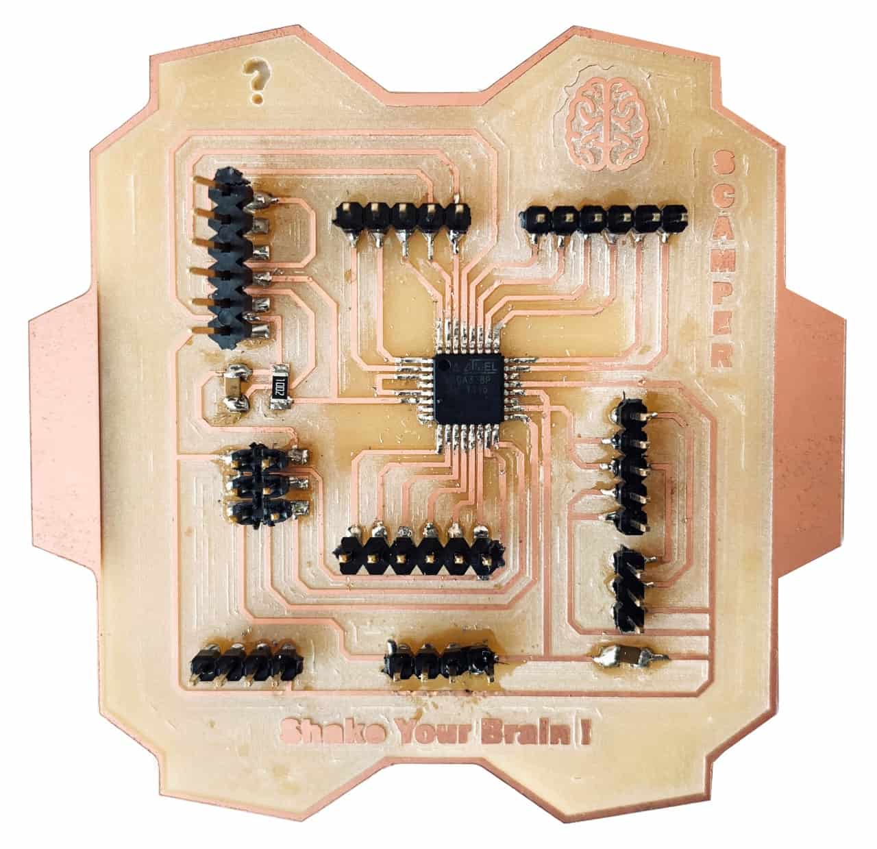
Soldering the components:
After that, I collected the components needed and soldered them.
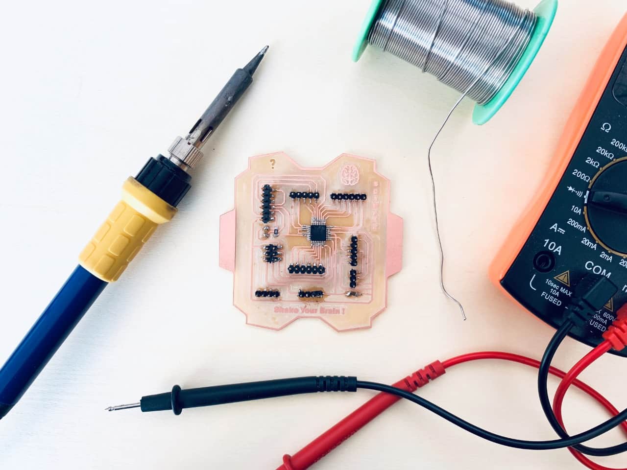
Hero shot!
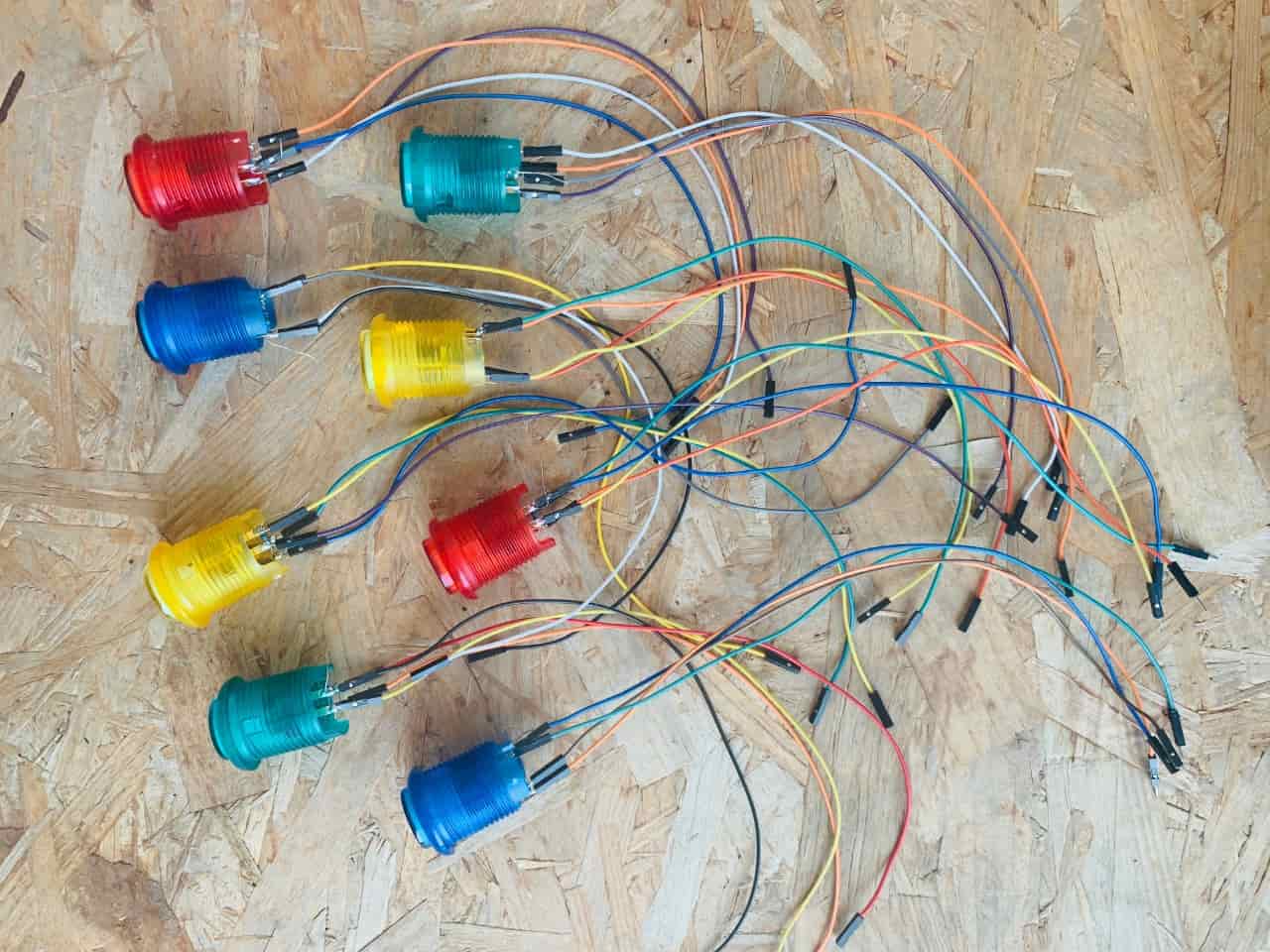
Also, I used the soldering to solder the Arcade LED Push Buttons.
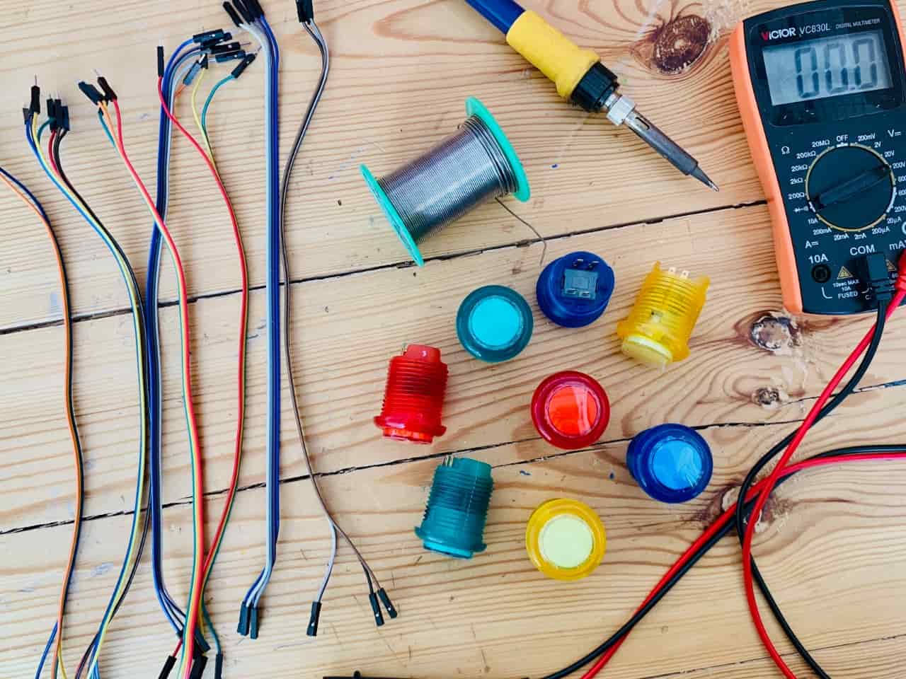
How to solder this Arcade LED Push Buttons ?
Testing the PCB:
Now, the PCB is ready! Once the soldering is done, I tested the board by uploading a simple test using Arduino as ISP to make sure that it works correctly without any shortcuts.
Blinking Code:
Uploading the code :
There are some steps I have to follow to upload the code to the microcontroller:
1. Connect the PCB with the Arduino by using female to male jumper wires between the ISP pins in the board and the Arduino. The pins that I am going to use are:
1. To make the Arduino as ISP > Open Arduino IDE software > Go to Tools > Then programmer > Choose Arduino as ISP.
2. To make the Arduino as ISP > Open Arduino IDE software > Go to Tools > Then programmer > Choose Arduino as ISP.
3. Then go to Tools > Board > Choose Arduino Pro or Pro mini.
4. Go to tools > Processor > Choose Atmega328P (3.3V, 8 MHz).
5. Connect the USB to the Arduino and computer port > Go to tools > Port > Choose the port for ex : ( COM6 ).
6. To upload the code > Go to sketch > Choose upload using programmer.
The test has been done successfully! Wahooo.
Let's start to connect the components!
Before connecting all the components to the PCB, I am going to do a quick test of the connection and code with Arduino to make sure that the system is working!
Preparing the code:
As the code is sequentially executed, I wrote down the commands to do the game's sequence. I started testing the parts separately and then connected them and integrated the code.
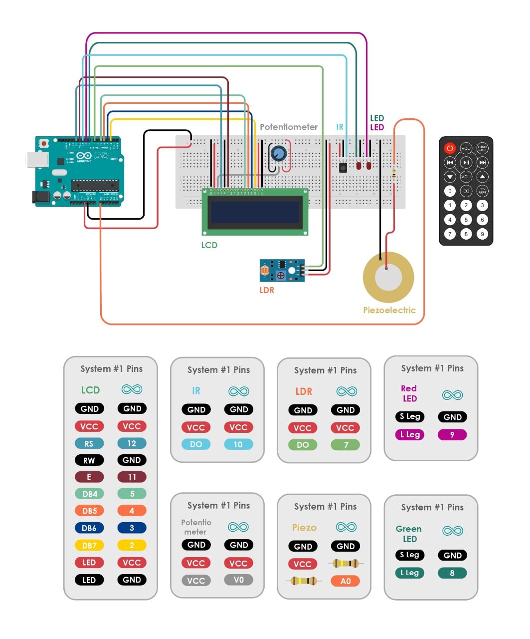
The first system components:
I talked about LCD screen and Potentiometer in output assignment. I will explain some new components.
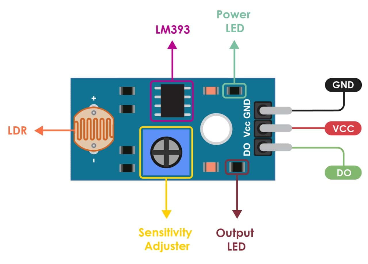
What is LDR Sensor ?
The LDR Sensor Module is used to detect the presence of light / measuring the intensity of light. The output of the module goes high in the presence of light and it becomes low in the absence of light. The sensitivity of the signal detection can be adjusted using potentiometer.
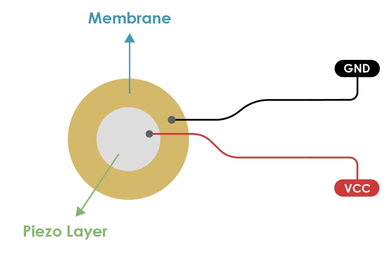
What is Piezoelectric Sensor ?
A sensor that utilizes the piezoelectric effect, to measure changes in acceleration, strain, pressure, and force by converting them into electrical charge is called as a piezoelectric sensor.
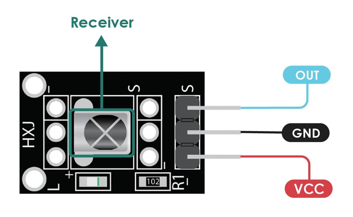
What is IR Receiver Module ?
IR receiver is hardware that sends information from an infrared remote control to another device by receiving and decoding signals. This code is then used in order to convert signals from the remote control into a format that can be understood by the other device.
IR Sensor Code :
As I am planning to use the IR Module. First, I connected IR to my board to extract the code for each IR remote control buttons what I need to use now are:
I did connect the following circuit.
Then, I uploaded the following code:
Then, I opened the serial port to start showing the code of each button.
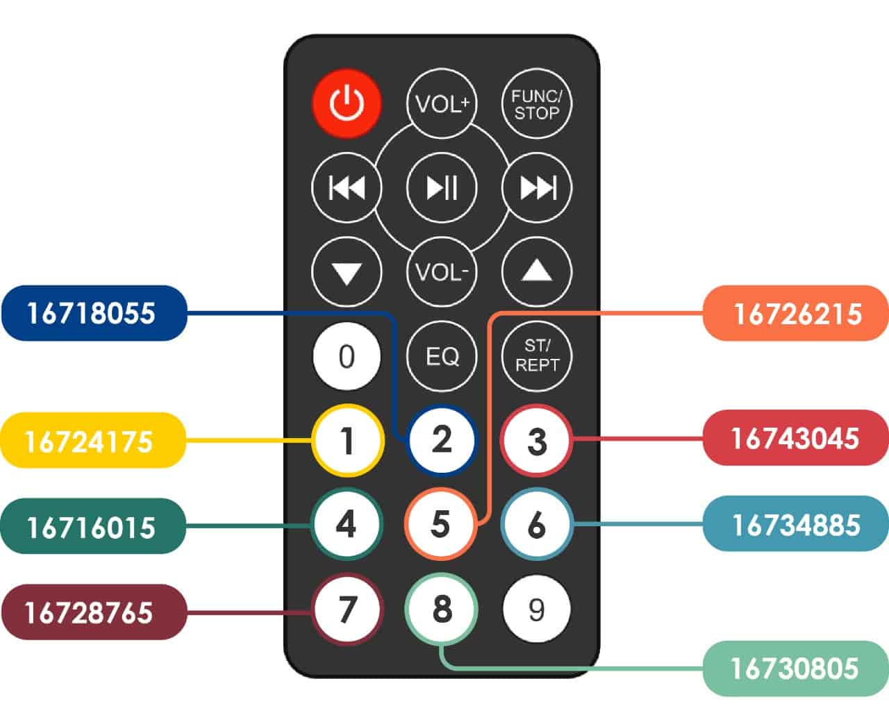
I picked the number from 1 to 8. so, the codes will be used in my main code.
The First System Connection :
The First System Code :
#include#include #include "pitches.h"
int IRpin = 10;
IRrecv irrecv(IRpin);
decode_results results;
int x=1;
int y=1;
int z=1;
const int rs = 12, en = 11, d4 = 5, d5 = 4, d6 = 3, d7 = 2;
LiquidCrystal lcd(rs, en, d4, d5, d6, d7);
In the void setup() section :
void setup() {
irrecv.enableIRIn();
lcd.begin(16, 2);
lcd.print("Shake Your Brain");
delay(4000);

pinMode(7,INPUT);
pinMode(8,OUTPUT);
pinMode(9,OUTPUT);
pinMode(A1,INPUT);
pinMode(A2,INPUT);
pinMode(A0,INPUT);
pinMode(6,OUTPUT);
In the void loop() section :
void loop() {
lcd.clear();
lcd.setCursor(0, 0);

lcd.print("Time to warm up");
for (int i=20 ; i>=0 ; i--){
    lcd.clear();
 lcd.setCursor(0, 0);

  lcd.print("Time to warm up");
    lcd.setCursor(0,1);
    lcd.print(i);


    if(digitalRead(A1)==1){
      digitalWrite(9,HIGH);
    }
    else{
      digitalWrite(9,LOW);
    }

    if(digitalRead(A2)==1){
      digitalWrite(8,HIGH);
    }
    else{
      digitalWrite(8,LOW);
    }
    delay(1000);
if(i<=3 && i>0){
      digitalWrite(8,HIGH);
      delay(1000);
       digitalWrite(8,LOW);
      delay(1000);
if(i==0){
      for(int y=5; y>=0; y--){
       digitalWrite(8,HIGH);
      delay(100);
       digitalWrite(8,LOW);
      delay(100);}
lcd.clear();
    lcd.setCursor(0, 0);


  lcd.print("Pick the Remote");
    lcd.setCursor(0, 1);

  lcd.print("To choose Leader");
while(x==1){

  if (irrecv.decode(&results))
    {

      irrecv.resume();
    }
if (results.value == 16726215)
     {
       lcd.clear();
    lcd.setCursor(0, 0);

  lcd.print("U R the Leader");
digitalWrite(9,HIGH);
delay(3000);
digitalWrite(9,LOW);


x=0;

     }
     else{
      digitalWrite(8,HIGH);
delay(3000);
digitalWrite(8,LOW);
      }
     }

     delay(2000);
lcd.clear();
    lcd.setCursor(0, 0);

  lcd.print("First step");

    delay(2000);


    lcd.setCursor(0, 1);

  lcd.print("Choose User/Idea");

     delay(2000);
while(y==1){
        lcd.clear();

 lcd.setCursor(0, 0);

  lcd.print("Choose User/Idea");
      lcd.setCursor(0, 1);
 lcd.print("Knock once done");
 delay(100);
if(analogRead(A0) > 300){
  y=0;
  lcd.clear();
    lcd.setCursor(0, 0);

  lcd.print("Good Job");
  delay(3000);
while(z==1){
 lcd.clear();
    lcd.setCursor(0, 0);

  lcd.print("Build Your Idea");
  delay(150);
if(digitalRead(7)==1){
    lcd.clear();
    lcd.setCursor(0, 0);

  lcd.print("You Are Done!");

   delay(150);
  lcd.setCursor(0, 1);
    lcd.print("Congrats!");
  delay(5000);
 lcd.clear();
    lcd.setCursor(0, 0);

  lcd.print("You are about to");
   lcd.setCursor(0, 0);

  lcd.print("Start new Idea!");
  delay(3000);
  z=0;
The second system components:
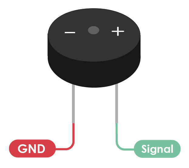
What is Buzzer ?
The buzzer consists of an outside case with two pins to attach it to power and ground.
The second system connection:
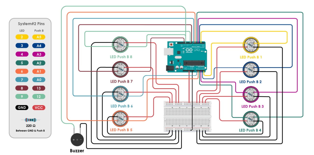
The second code:
#include "pitches.h"
int LED1 = 2;
int PBU1 = A5;

int LED2 = 3;
int PBU2 = A4;

int LED3 = 4;
int PBU3 = A3;

int LED4 = 5;
int PBU4 = A2;

int LED5 = 6;
int PBU5 = A1;

int LED6 = 7;
int PBU6 = A0;

int LED7 = 8;
int PBU7 = 13;

int LED8 = 9;
int PBU8 = 12;

int LEDG = 10;
int LEDR = 11;
int x =1;
int y =1;
int z =1;
In the void setup( ) section :
//Serial.begin(9600);
  pinMode(LED1, OUTPUT);
  pinMode(LED2, OUTPUT);
  pinMode(LED3, OUTPUT);
  pinMode(LED4, OUTPUT);
  pinMode(LED5, OUTPUT);
  pinMode(LED6, OUTPUT);
  pinMode(LED7, OUTPUT);
  pinMode(LED8, OUTPUT);
  pinMode(LEDG, OUTPUT);
  pinMode(LEDR, OUTPUT);

  pinMode(PBU1, INPUT);
  pinMode(PBU2, INPUT);
  pinMode(PBU3, INPUT);
  pinMode(PBU4, INPUT);
  pinMode(PBU5, INPUT);
  pinMode(PBU6, INPUT);
  pinMode(PBU7, INPUT);
  pinMode(PBU8, INPUT);
digitalWrite(2, HIGH);
digitalWrite(3, HIGH);
digitalWrite(4, HIGH);
digitalWrite(5, HIGH);
digitalWrite(6, HIGH);
digitalWrite(7, HIGH);
digitalWrite(8, HIGH);
digitalWrite(9, HIGH);
Assembly
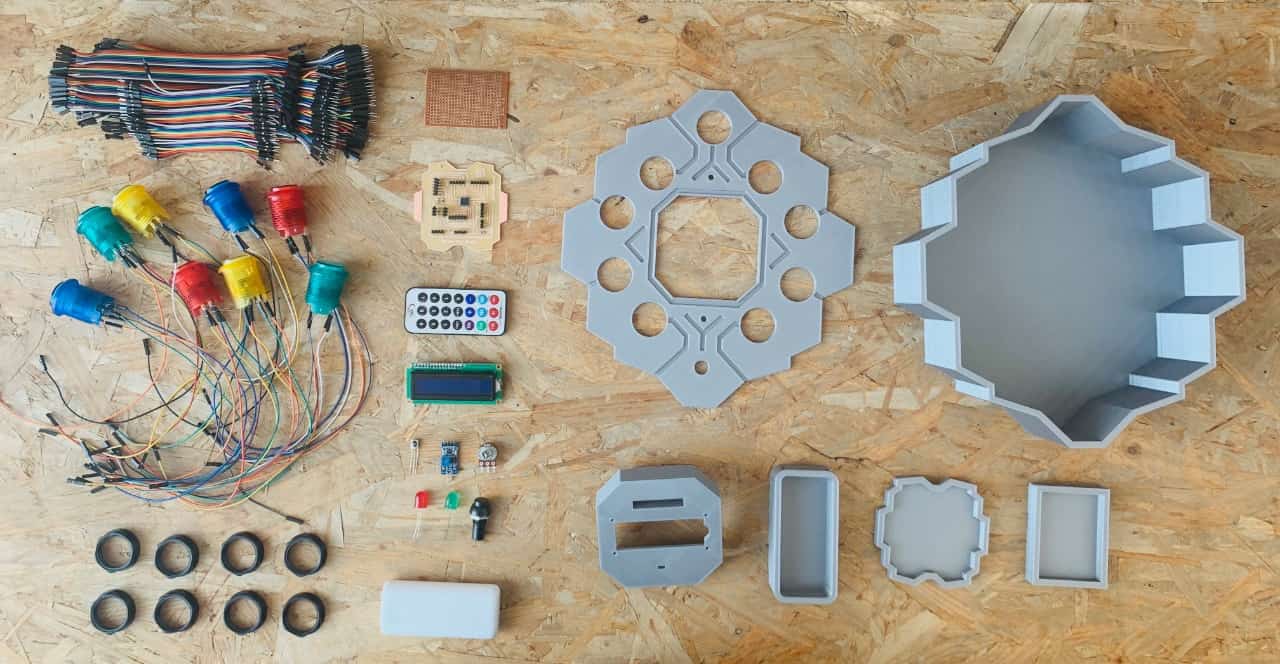
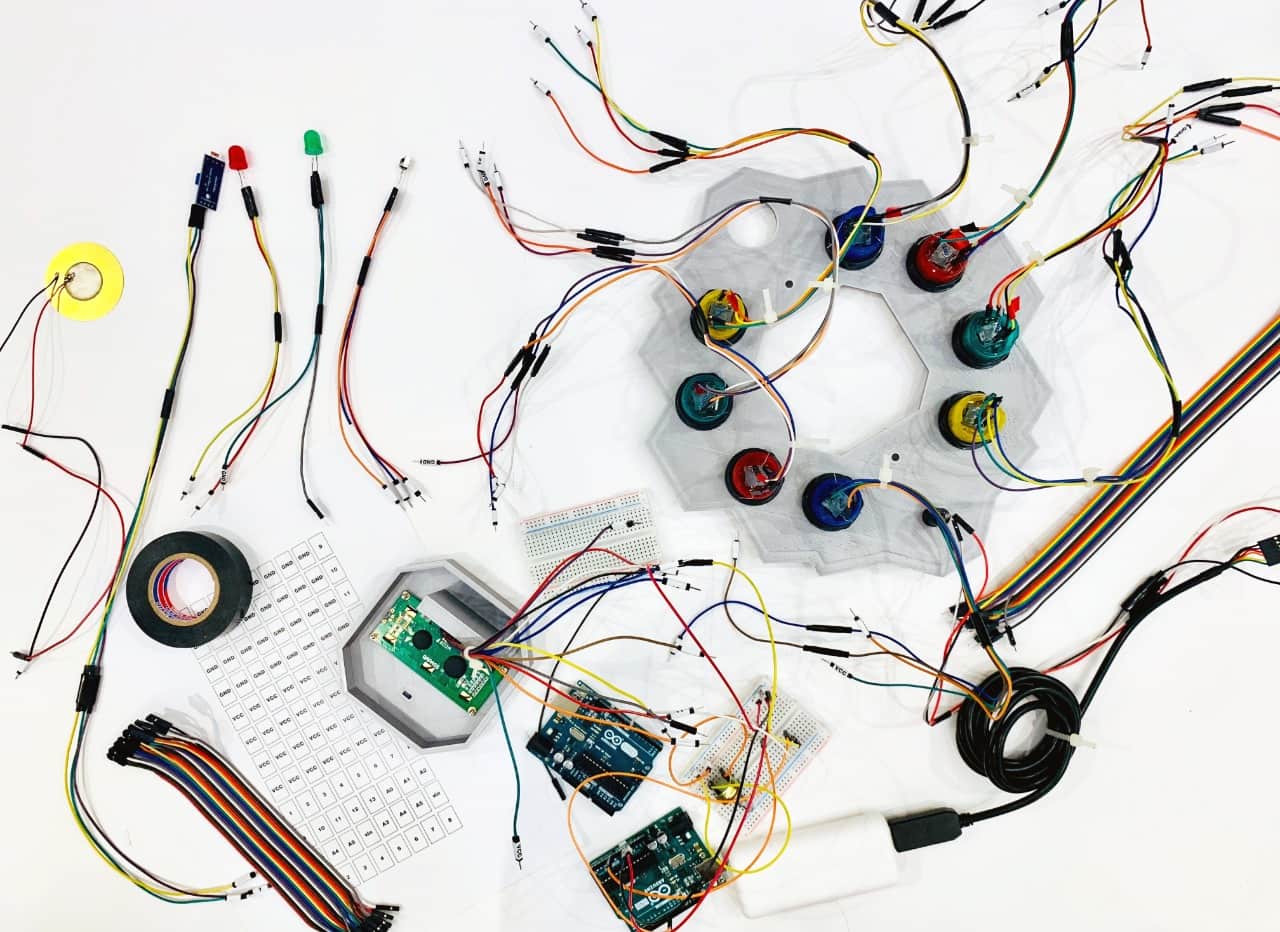
TOO MANY WIRES I CAN NOT CONTROL THEM!!! RELAX NORAH YOU WILL FIND SOLUTION!!
I have a lot of wires, and I got really lost while connecting the components. I am trying to organize the wires by doing labels and sticking them to both sides of the jumper wires to know the exact pin number.
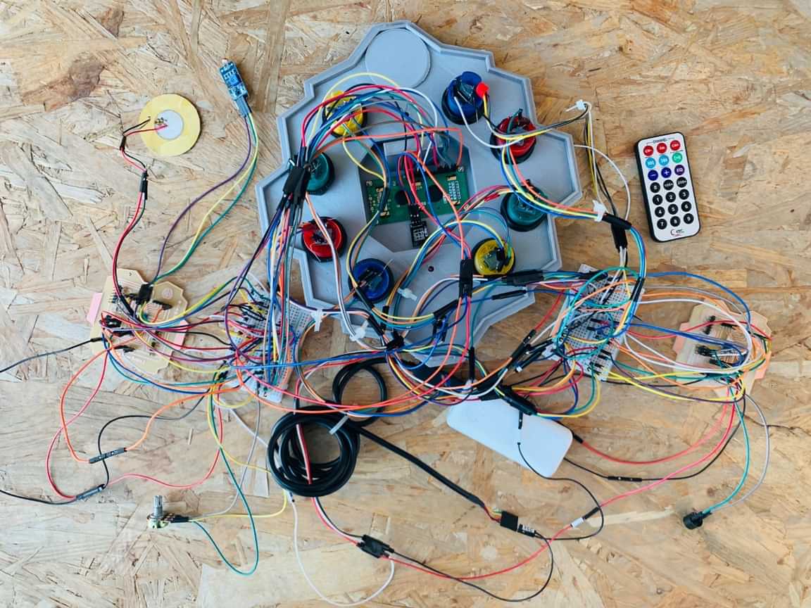
Final test and connection :
I connected all the components to the boards by following the datasheet of the microcontroller. Then, I uploaded the code to the microcontrollers and tested them. After that, I moved the microcontroller boards and components inside my project, and It was a bit difficult arranging the wires, but yah I MADE IT!
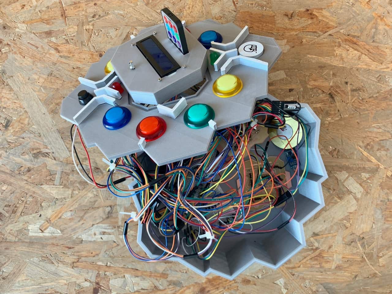
The Product
Final Poster
Final Video
Date : Monday - August 10, 2020
Time : 3:11 PM
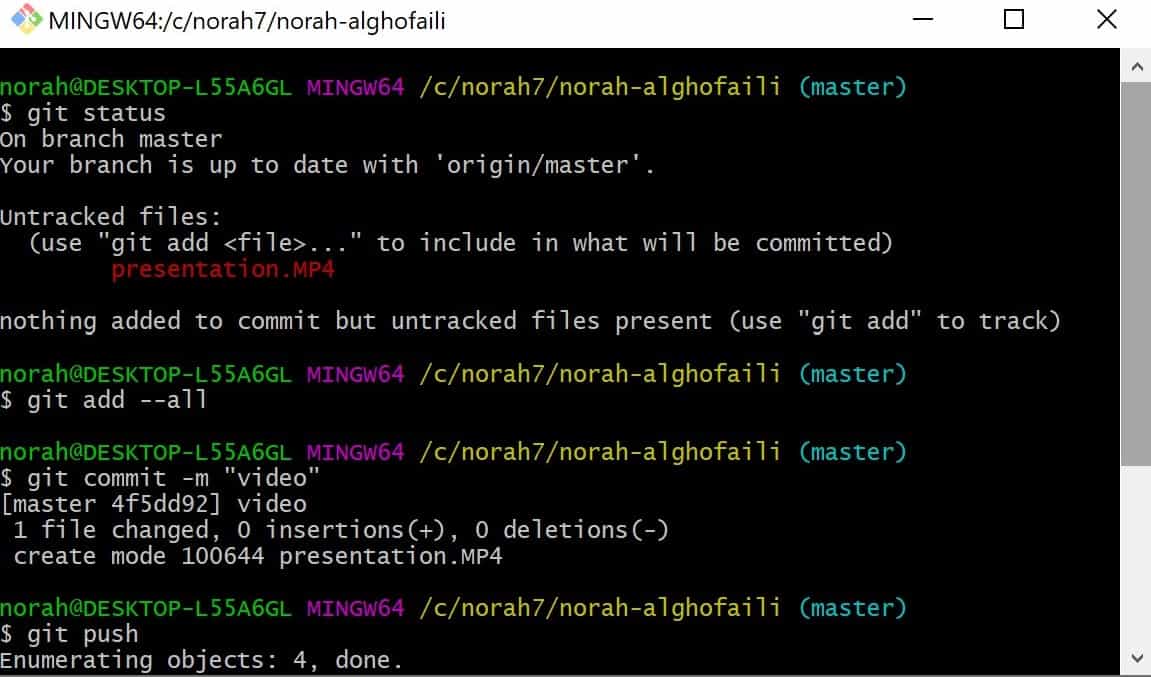
On this day, The journey of the final project has been done! Finally I pushed my final project!! I am so so so proud and happy!
Alhamdulillah.. Thank God!