< Embedded Programming />
Group Assignment
We have to compare the performance and development workflows for different microcontroller families.
You can check the group assignment in this link : Embedded Programning Group Assignment.
Individual Assignment :
This week, we are supposed to program the PCB board which we have made in the previous assignment Electronic Design by using different programming languages and programming environments.
The goal of this assignment is to read the datasheet for the microcontroller, and to summarize the information. It also aims to program the board that we have made.
What is an embedded system ?
An embedded system is a computer system. A combination of hardware and software ( computer processors, computer memory, and input/output devices) that is designed to make functions.Embedded system has microcontroller as the main part which controls all the operations required through them.
What is the purpose of embedded systems?
The purpose is to control the device and to allow a user to interact with it.
Where is the embedded system used ?
There are many examples of an embedded system in the appliances and devices we use. Examples are:
What is the difference between an Embedded System & a Computer ?
There are some basic differences between an embedded System and a Computer:
The Computer:
An Embedded System:
How do I get into embedded programming?
Datasheet Summary:
I read about the microcontroller that we were working on. It is called Attiny44. As a beginner, I did not understand a lot of information in the datasheet, but I tried to summarize the most important information.
The main features of Attiny44 :
Describing the pins
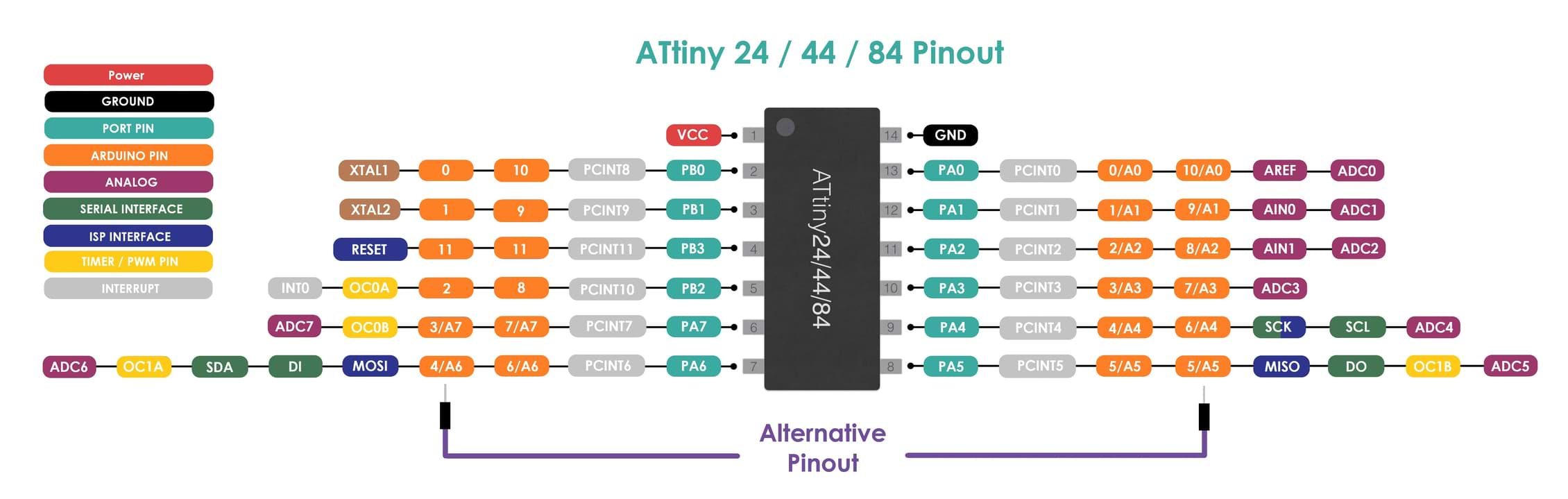
VCC : Supplies voltage. This is where I can connect the battery or any power source to energize the microcontroller chip.
GND : Ground. I connect this to the ground or negative from the power source to complete the circuit and power it up.
RESET : Reset input. This has a low activity, it means that I can reset once I send a low voltage level. The reset pin can also be used as a (weak) input/output pin.
There are two types of ports :
Port A (PA7:PA0) : Port A is an 8-bit bi-directional iInput/output port with internal pull-up resistors (selected for each bit). 8 bits means that the output voltage level can be described from 0-255 in decimal and will be equal to 0-5volts. Internal pull-up resistor means that I can connect a push button without using/adding external current limiting resistor, and I can utilize the internal one to protect the microcontroller chip.
Port B (PB3:PB0) : Port B is a 4-bit bi-directional iInput/output port with internal pull-up resistors (selected for each bit).
PCB Board Test
As you know, number of Covid-19 cases has increased in our cities, and so we have a 24 hour curfew. We couldn’t access our lab in order to solder the PCB board. In this case, I am going to use my small Arduino kit to test some programming languages.
The main components that I am going to use in this assignment are :
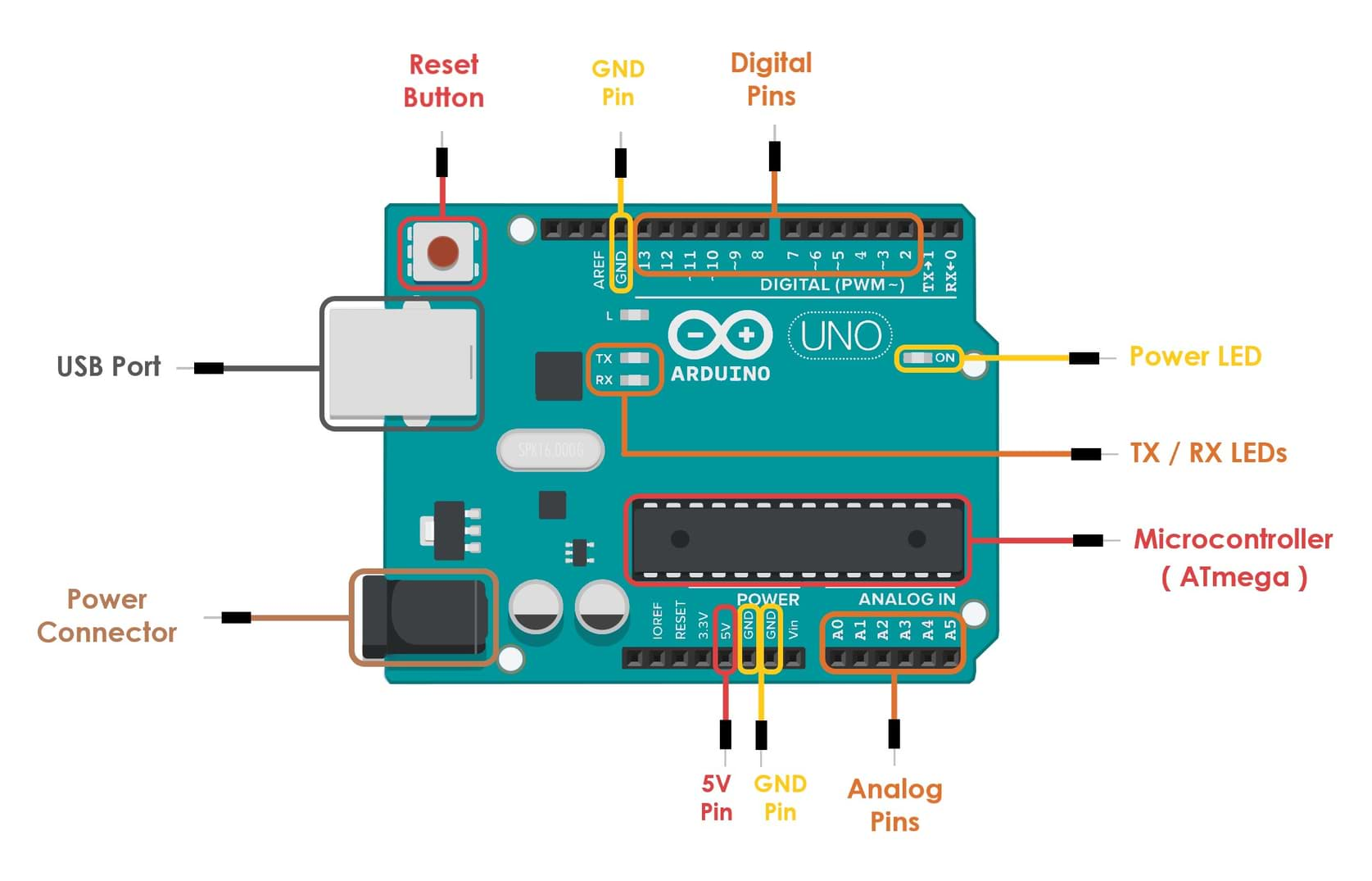
Arduino
Arduino is an open-source prototyping platform consisting of both a physical programmable circuit board and a software used for building electronics projects.
The Arduino Uno is a microcontroller board based on the ATmega328. It contains everything needed to support the microcontroller such as :
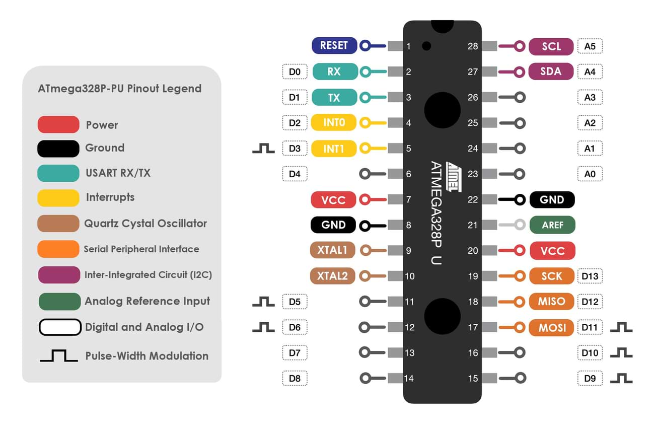
ATmega328 Microcontroller
The ATmega328 is a single-chip microcontroller created by Atmel in the megaAVR family. It is an 8-bit and 28 Pins AVR Microcontroller, manufactured by Microchip, follows RISC Architecture and has a flash type program memory of 32KB.
ATmega328 features:
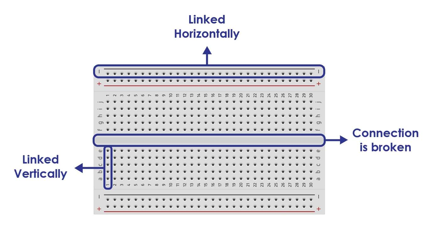
Breadboard
A breadboard is a platform used to build and test electronic circuits, usually without having to do any soldering.
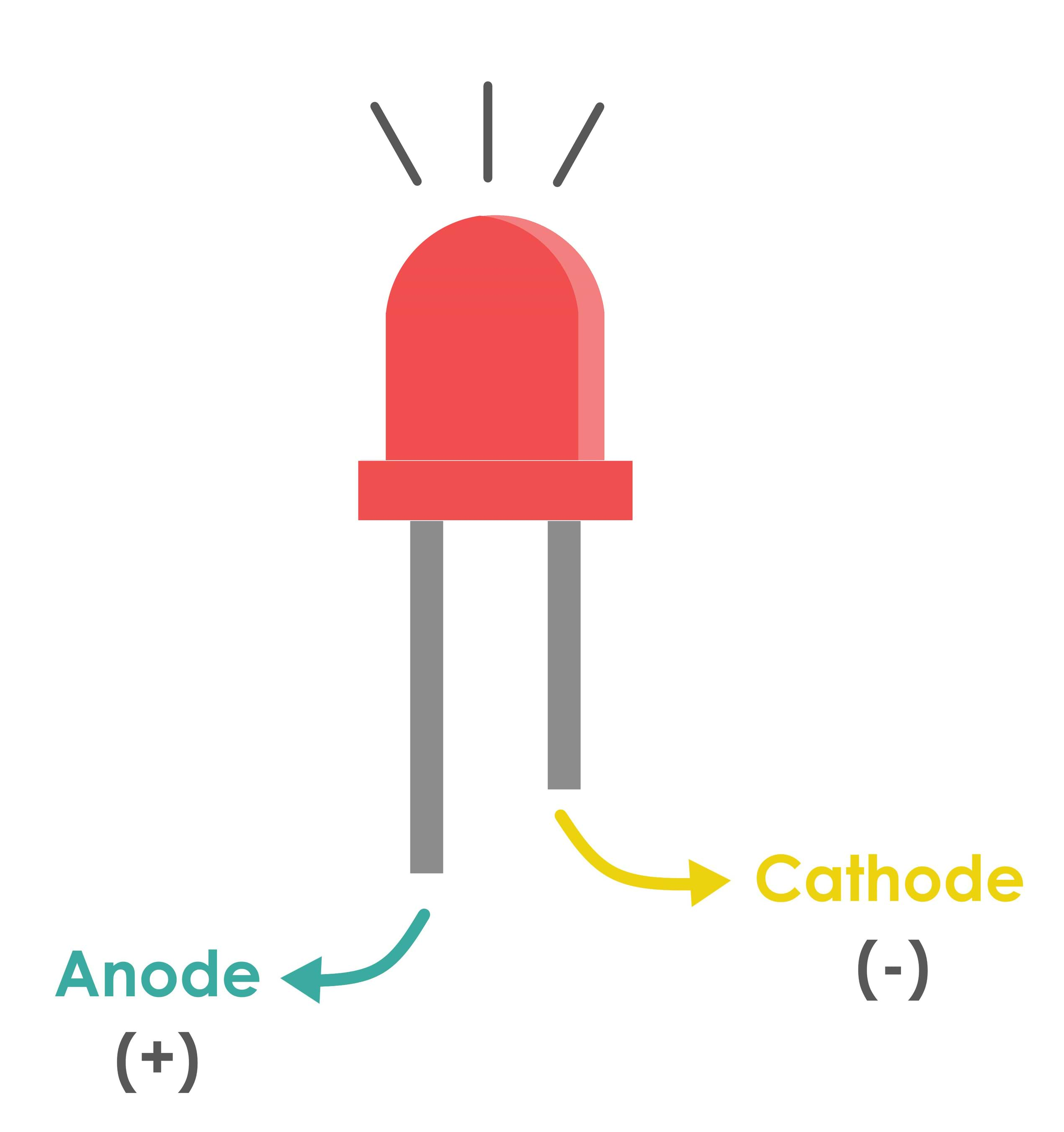
LED
LED is lighting emitting diodes. It consists of two legs ( Anode and Cathode ).
Anode : The longer leg (called the anode) is positive and must connect to the positive terminal.
Cathode : The shorter leg (called the cathode) must connect to the negative or ground terminal.
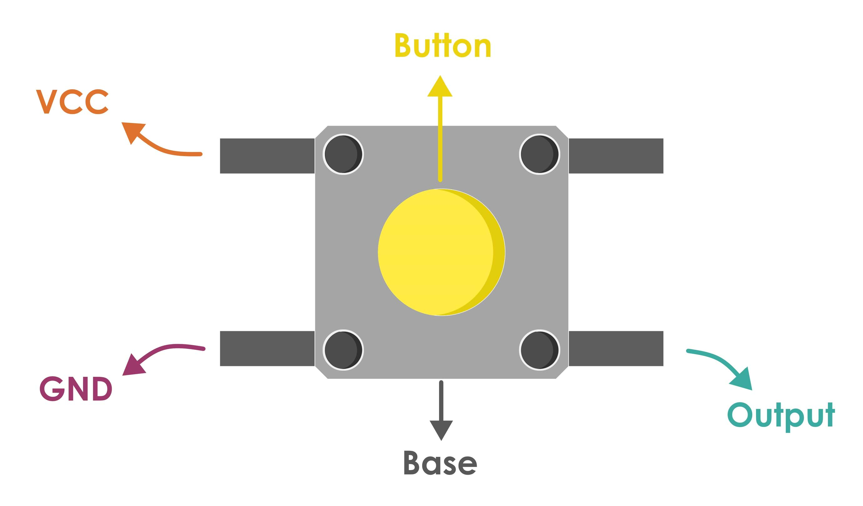
Push Button
A push-button is a simple switch mechanism to control some aspect of a machine or a process. It is easily depressed or pushed by the human finger.
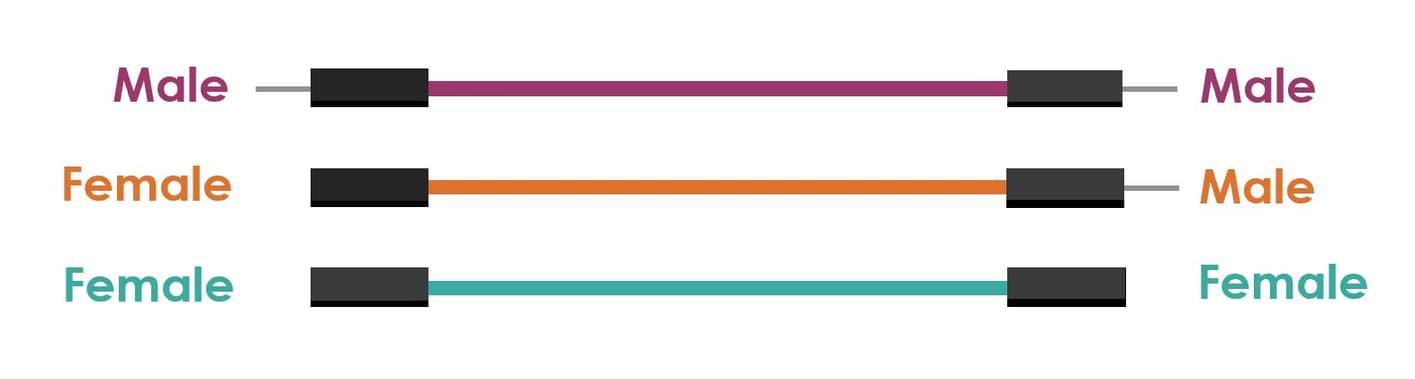
Jumper wires
Jumper wires are simply wires that have connector pins at each end. These wires help us to connect two points in the circuit by using a breadboard and easily change the connection as needed.
Jumper wires have three different types :
The difference between each is in the end point of the wire. Male ends have a pin protruding and can plug into things, while female ends do not and are used to plug things into.
Resistors
A resistor is an electrical component that limits or regulates the flow of electrical current in an electronic circuit. It can also be used to provide a specific voltage for an active device.
There are two types of resistors which have linear properties.
Fixed Resistors : It is a resistor which has a specific value and we can’t change the value of fixed resistors.
Variable Resistors : The values can be changed through a dial, knob, and screw or manually by a proper method.
In this assignment, I’m going to use the fixed resistor. There are many types of this type of resistor.
Let’s take a close look at a resistor.
Resistor Color Coding :
Every resistor has a set of color bands printed on its casing which tells us what the value of the resistor is. While there are resistors with 3,4,5 and 6 even 1 band, the most commonly found resistors have 4 bands.
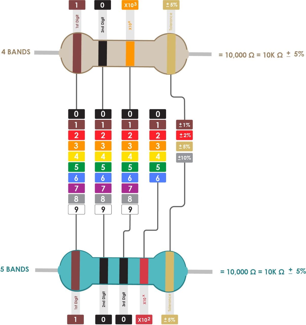
What is Tolerance ?
Tolerance is the percentage of error in the resistor's resistance, or how much more or less you can expect a resistor's actual measured resistance to be from its stated resistance.
Resistor Power Triangle :
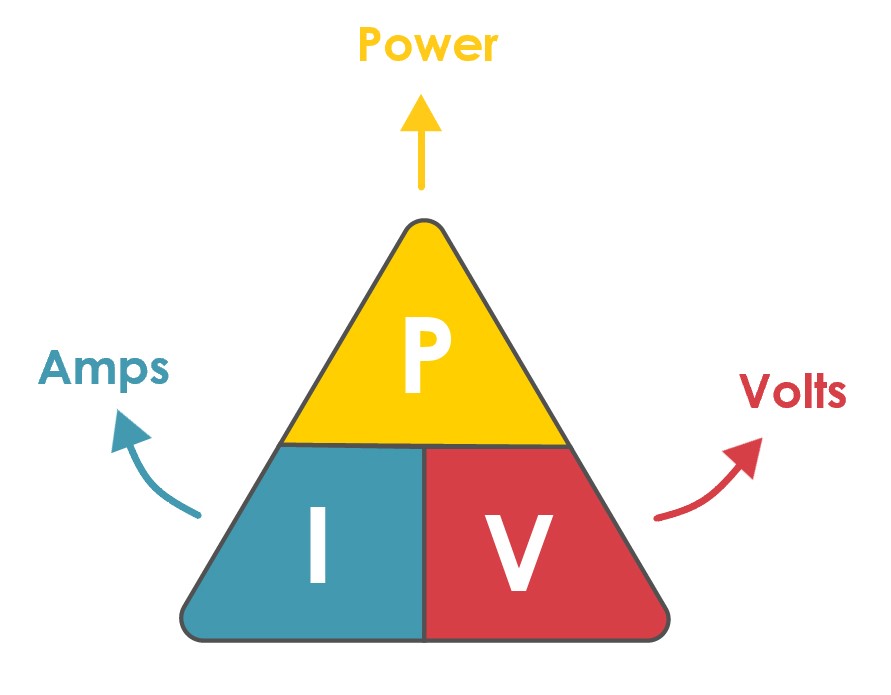
Using the Resistor Power Triangle is the best way to calculate the power dissipated in a resistor if we know the values of the voltage and current across it. Ohms law allows us to calculate the power dissipation given the resistance value of the resistor.
[ P = V x I ] Power = Volts x Amps
[ P = I2 x R ] Power = Current2 x Ohms
[ P = V2 ÷ R ] Power = Volts2 ÷ Ohms
Now, let's talk about the programming lnguages:
There are many different programing languages, some of which are:
Let's do it !
I’m going to use 3 different programming software and languages:
Programming by Using Mblock Software :

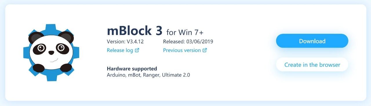
To download the software, click here: Mblock Software
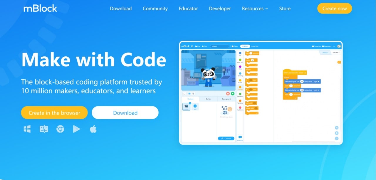
What is a Mblock Software ?
Mblock is a STEAM programming software package based on MIT's. It’s easy to learn and designed for kid’s programming.
How do you use it ?
The interface of Mblock is designed to look like a puzzle, where the user puts together different pieces (blocks) to build a program.
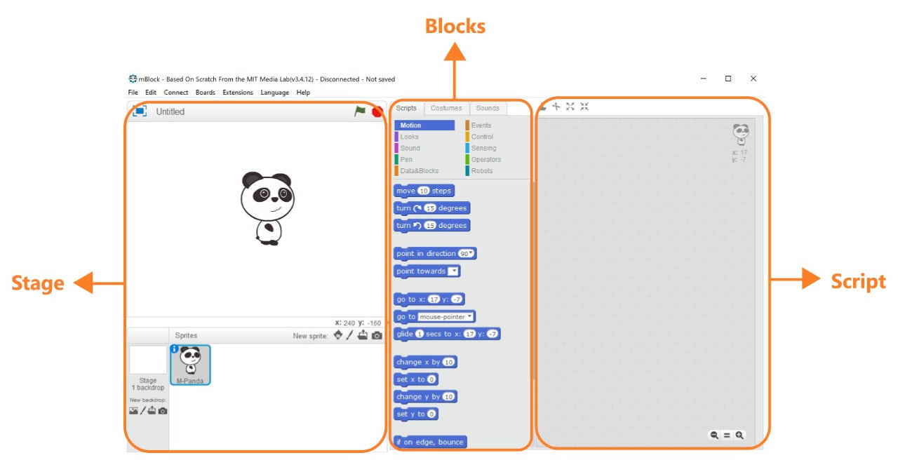
The main parts :
Stage : To see the outcome of what your code does and also access your devices, sprites, and backgrounds.
Blocks : There are many different color categories, such as motion, looks, sound, and pen. All these categories contain preset code blocks that you can drag and drop into the right side (Script).
Script : To build your program. Place your code to make your game. Anything that goes on this area affects the Stage.
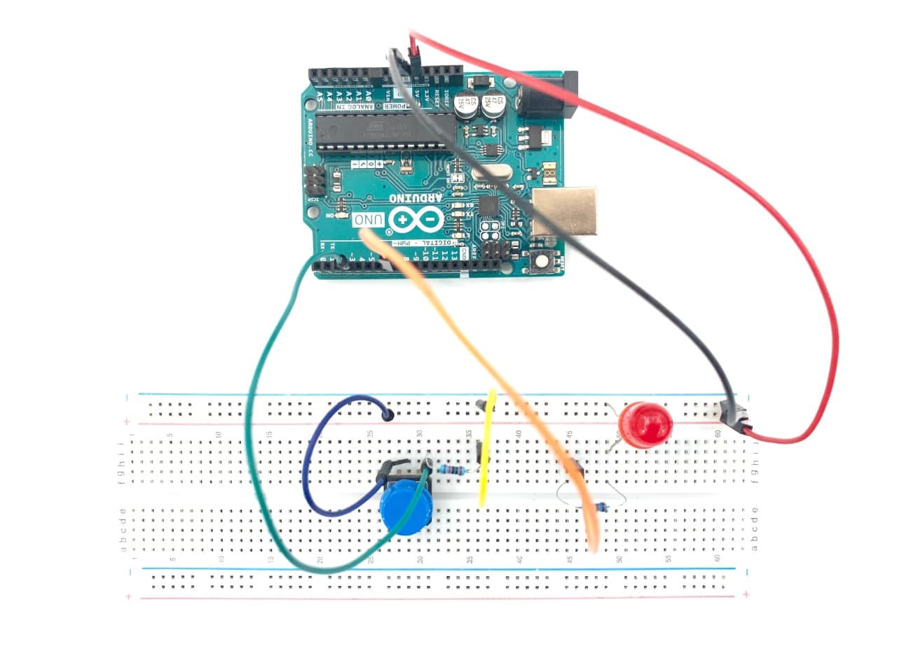
Push Button and LED Test :
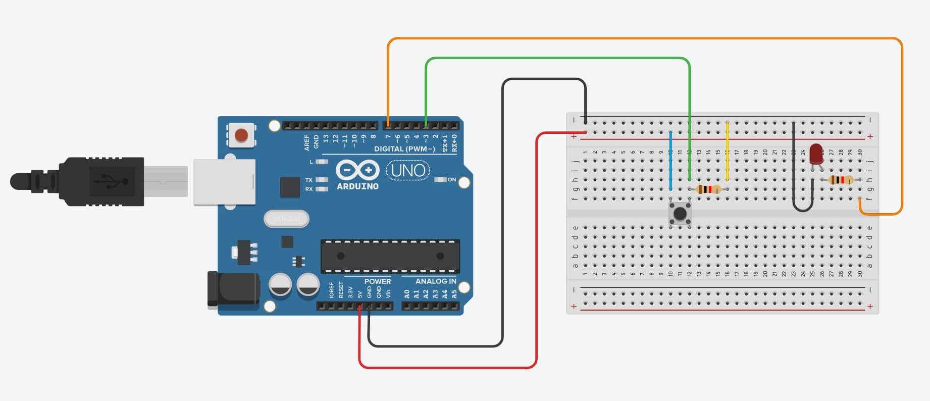
Let’s connect the components !
I will use the following components:
Now let’s program !
After connecting all the components, all you have to do is to follow these steps:
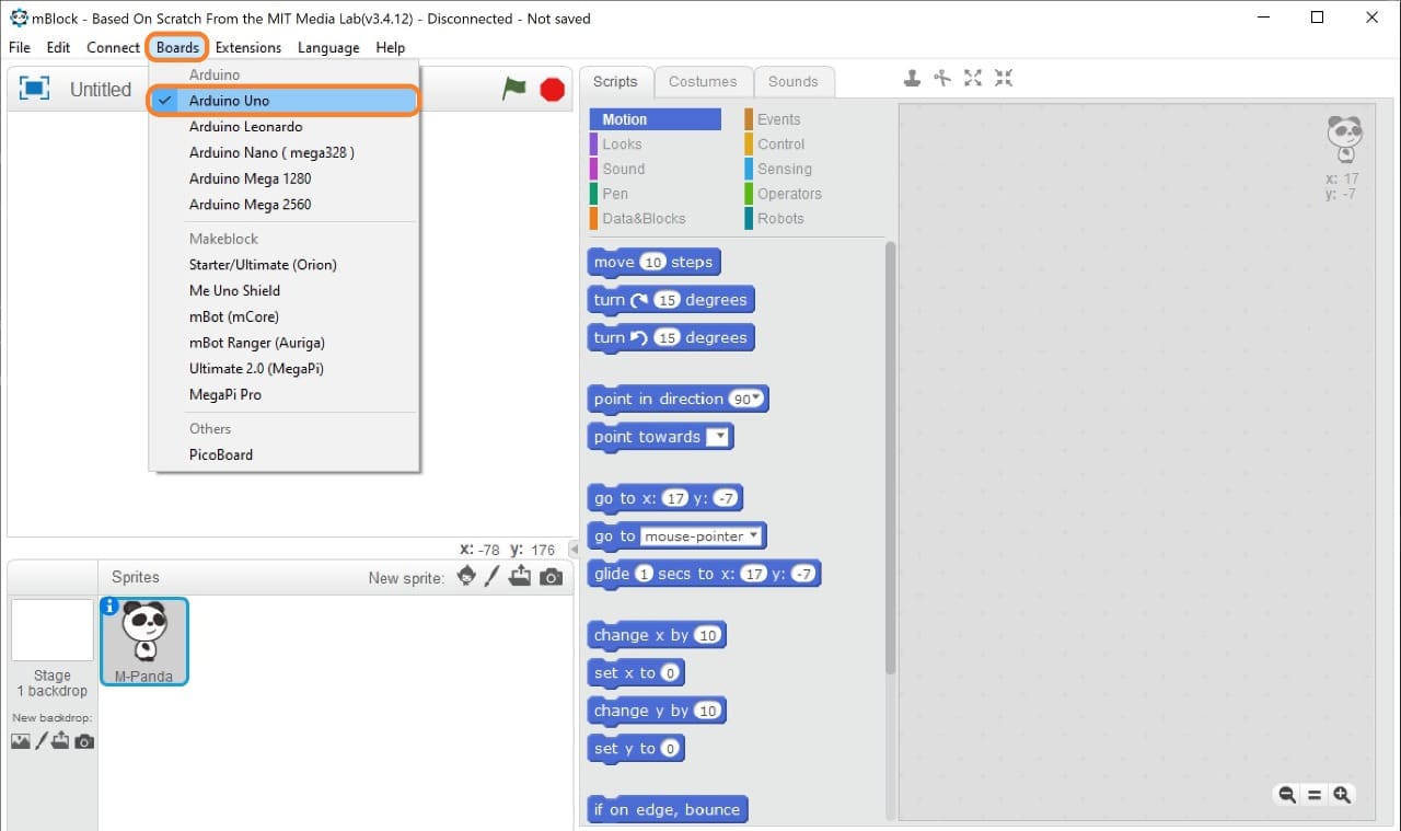
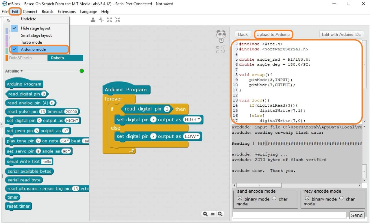
1. Open Mblock software > Go to Boards > Arduino Uno.
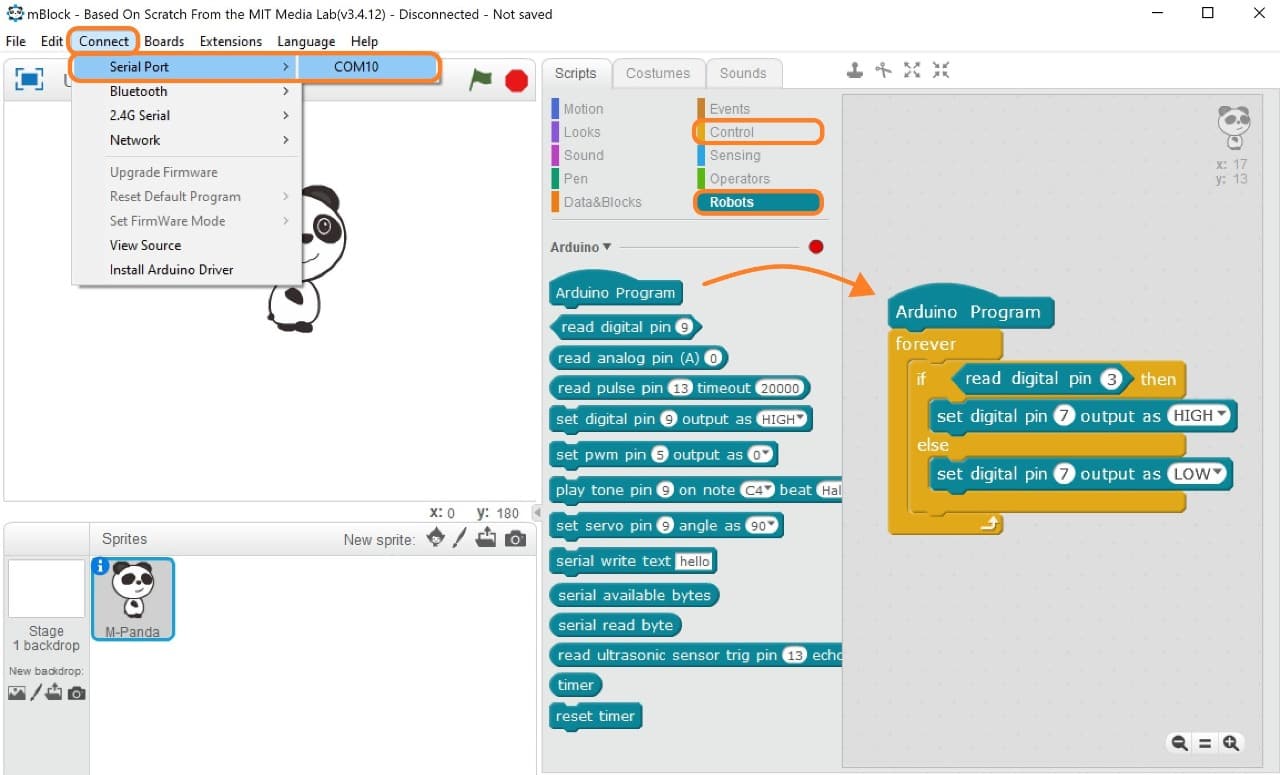
2. Start dragging the code from blocks area to Script area > Connect the Arduino with the computer by using USB port > Then go to connect and choose the serial port (COM10).
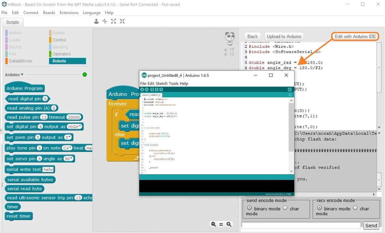
3. To open the arduino mode window > Go to edit > Arduino mode > Click on upload to Arduino.
4. Also we can edit the code from Arduino IDE.
LED and Push Button Code :
When we push the button, the LED will turn ON. And if not the LED will be OFF.
const int ledPin =  7;
const int buttonPin = 3;
Void Setup Section :
pinMode(3,INPUT);
pinMode(7,OUTPUT);
Void Loop Section :
if (digitalRead(3) == LOW) {
digitalWrite(7, HIGH);
} else
digitalWrite(7, LOW);
Arduino Programming and Testing :
ATtiny44 Programming and Testing :
To test the PCB I am going to use the same board that I have designed it in the previous assignment. To get more information about how to program ATtiny44 microcontroller check Electronics Design Assignment.
It is working !
Programming by Using Arduino IDE Software :

To download the software: Arduino software
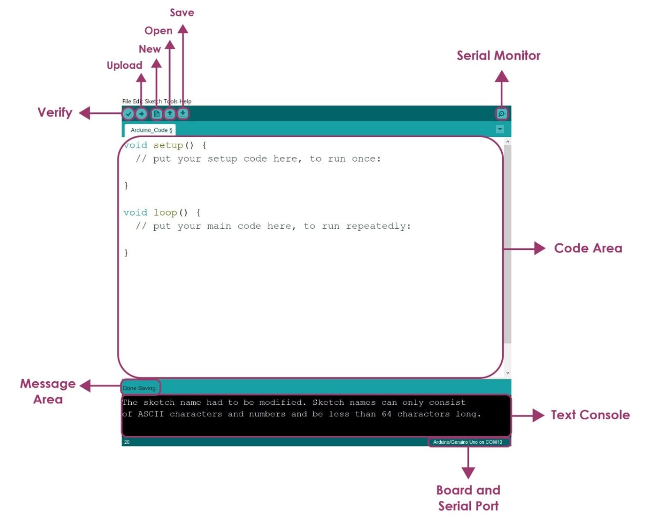
What is an Arduino Software ?
Arduino is an open source electronics platform based on easy to use hardware and software. Arduino boards are able to read inputs and output devices.
The main parts of IED:
Fading LED Test :
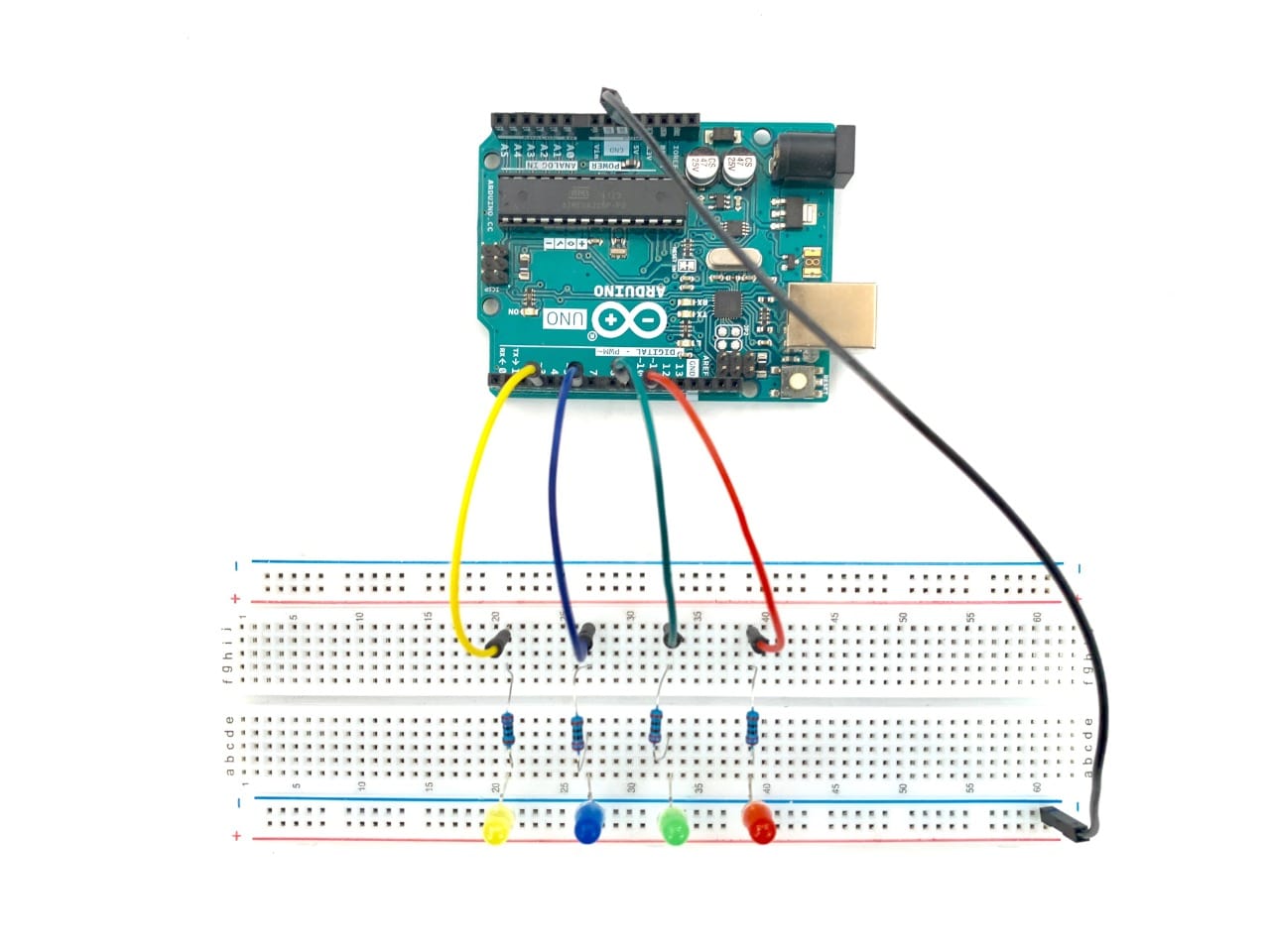
Let’s connect the components!
I will use the following components:
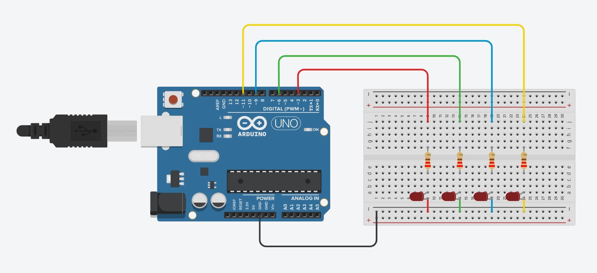
Let’s Program !
After connecting all the components, you have to follow these steps:
1. Open Arduino software > Then write the code.
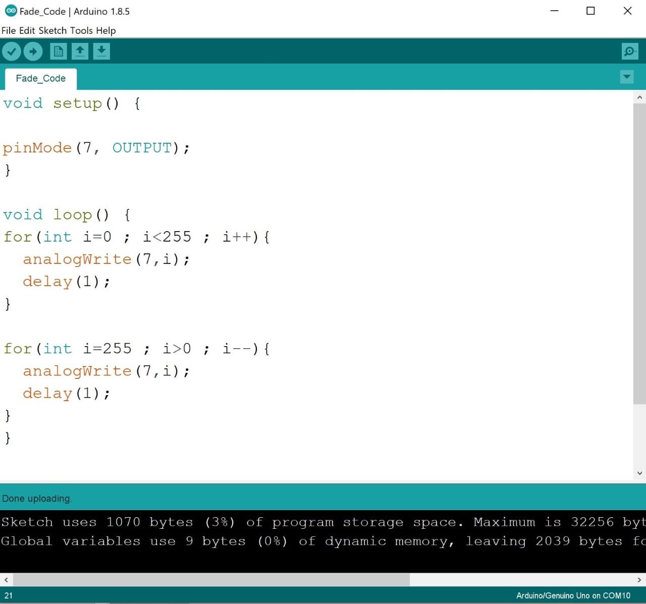
Fade Code :
This code shows how to fade an LED on pin 7 using the analogWrite() function.
Void Setup Section :
pinMode(7, OUTPUT);
Void Loop Section :
for(int i=0 ; i<255 ; i++){
analogWrite(7,i);
delay(1);
for(int i=255 ; i>0 ; i--){
analogWrite(7,i);
delay(1);
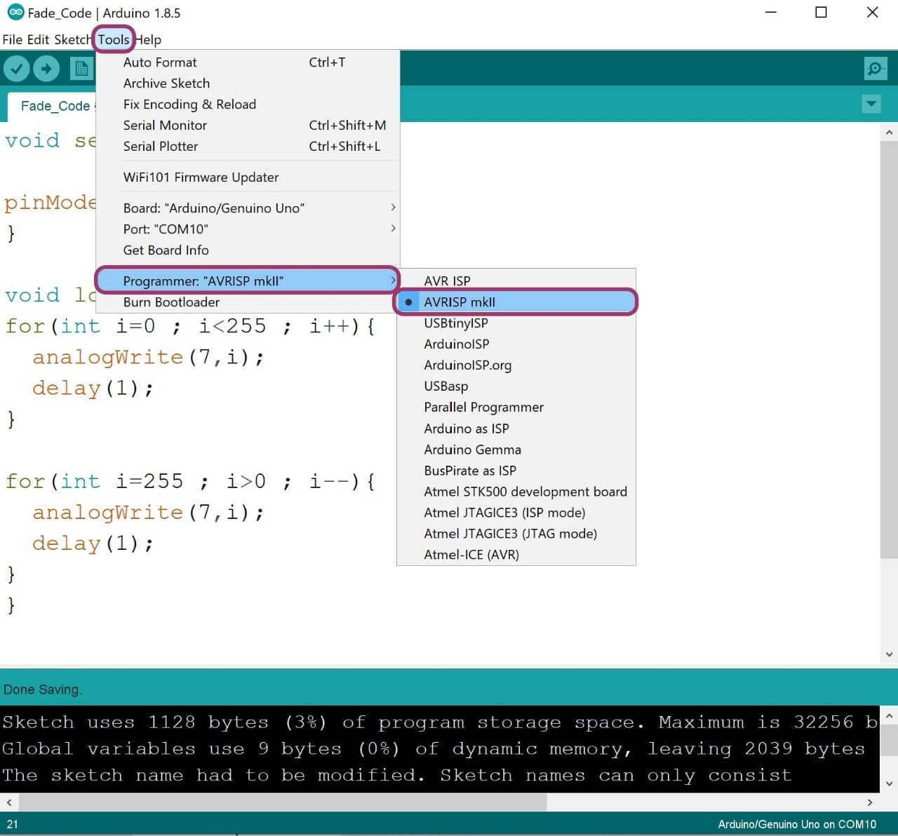
2. To upload the code the Arduino Go to Tools > Board > Arduino/Genuino Uno.
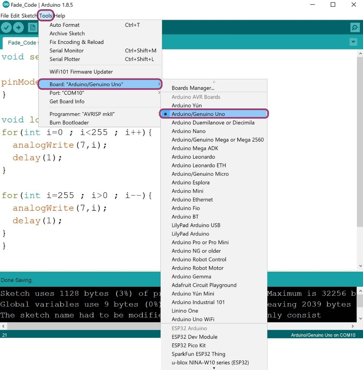
3. Then Go to Tools > Programmer > Choose AVRISP mkll.
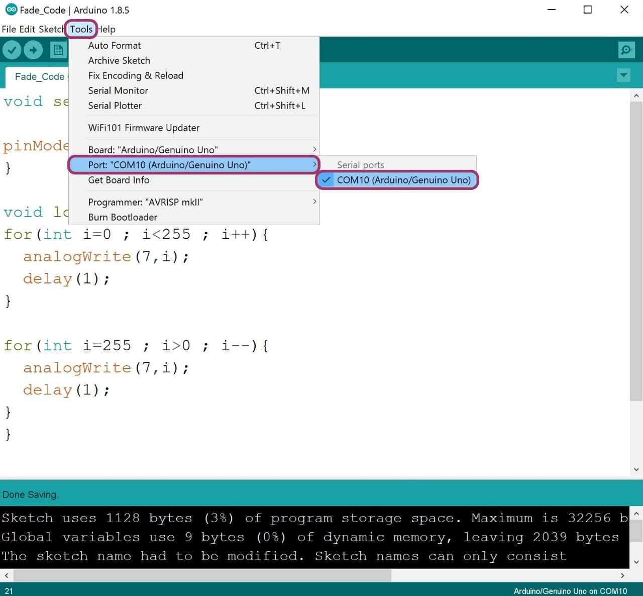
4. After that connect the arduino to the computer by using USB port > Then go to Tools > Port > COM10.
5. Click on Verify > Then Upload.
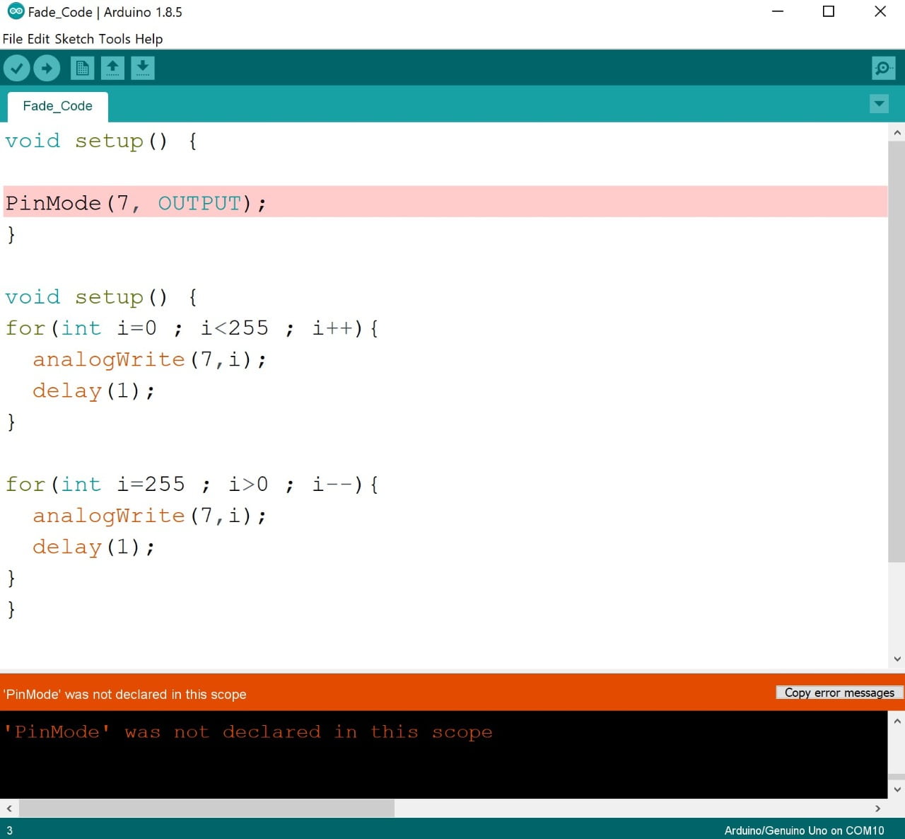
Oops ! ERROR, ERROR, ERROR !!
I faced some errors while trying to verify the code and I learned how to solve these errors by researching about them and asking my instructor to guide me.
There are the errors:
1. I wrote the word PinMode in the wrong way. The P letter should be small letter (pinMode).
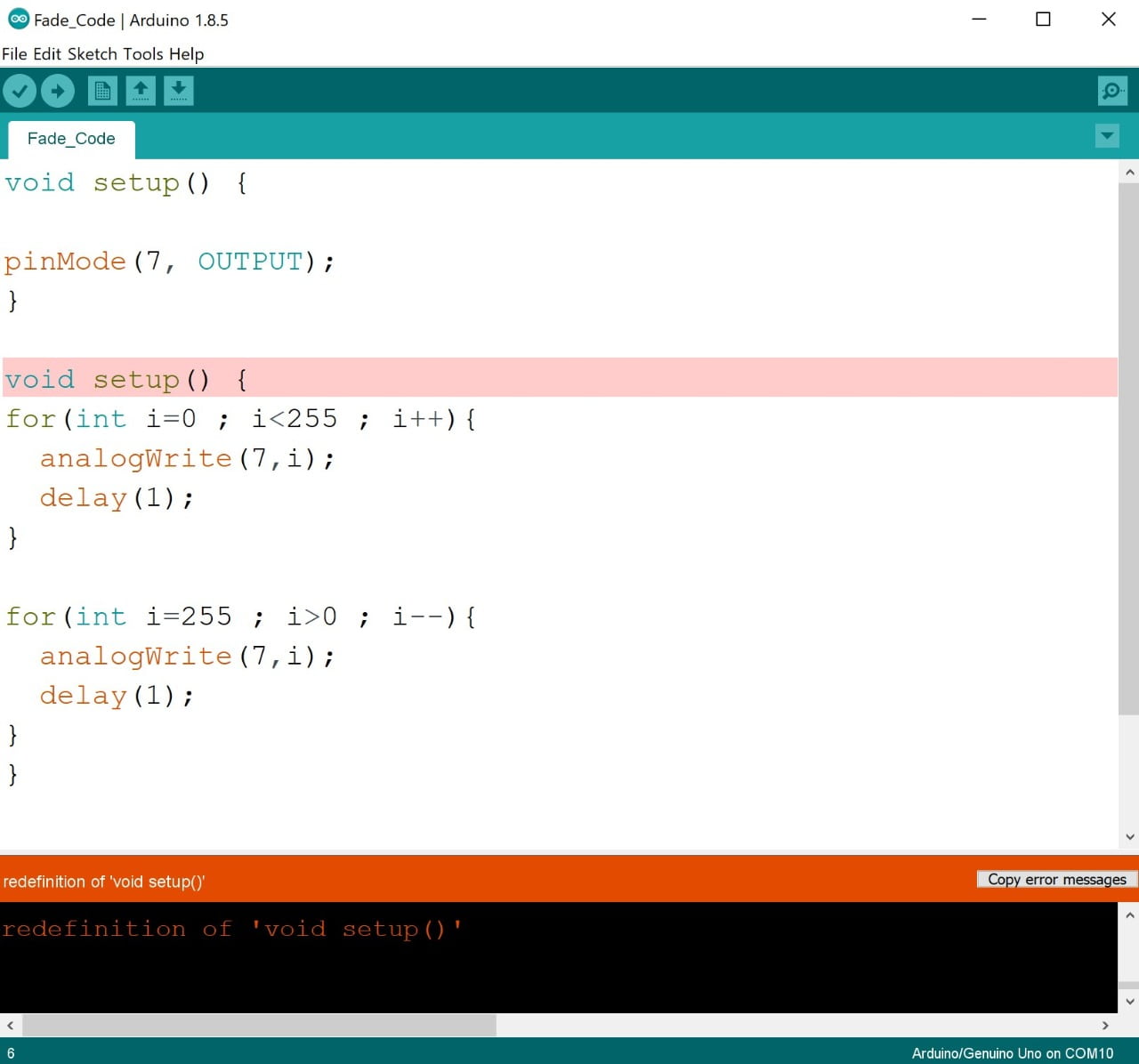
2. I wrote a void setup twice which is wrong. The second one should be a void loop.
The code has been uploaded successfully! Wahoooooooo I SOLVED IT !!! I’m Genius Right ? SAY YES, YES, YES! =)
Oops Oops !
I tried to use pin 7 with the Arduino test, but it did not work! I searched a lot for this problem and I noticed that the fading code demonstrates the use of analog output (PWM) to fade an LED.What is PWM ?
Pulse Width Modulation, or PWM, is a technique for getting analog results with digital means. Digital control is used to create a square wave, a signal switched between on and off. This on-off pattern can simulate voltages in between full on (5 Volts) and off (0 Volts) by changing the portion of the time the signal spends on versus the time that the signal spends off.
There are limited PWM pins. On most Arduino boards, the PWM function is available on pins 3, 5, 6, 9, 10, and 11. The frequency of the PWM signal on most pins is approximately 490 Hz. On the Uno and similar boards, pins 5 and 6 have a frequency of approximately 980 Hz.
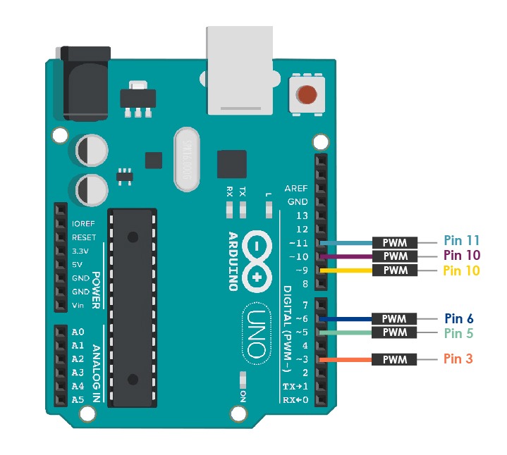
So, I used PWM pins (3, 6, 9 and 11) with Arduino test. For ATtiny44 Microcontroller PMW pins are (5, 6, 7 and 8) and I used pin 7 because LED in the PCB is connected with pin 7.
Arduino Programming and Testing :
ATtiny44 Programming and Testing :
The tests have been done perfectly! Wahooo.
Programming By Using C Language :
Technology is constantly changing. New microcontrollers become available every year. The one thing that has stayed the same is the C programming language used to program these microcontrollers.
What is C language ?
C programming language is a computer programming language that was developed to do system programming for the operating system.
To write code in C, we need software! I am going to use code blocks software.

What is Code Blocks Software ?
The code block is a popular application for C Programming. It is open source, cross-platform, free C, C++ and Fortran IDE. It builts to meet the most demanding needs of its users. It is designed to be very extensible and fully configurable.
To download CodeBlock software use this link : Code Block Software.
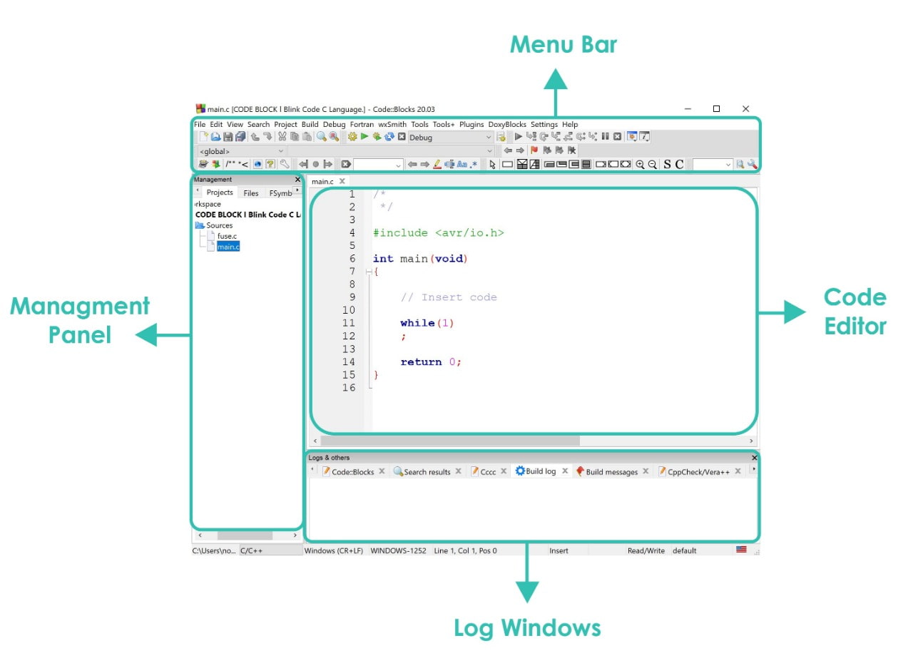
Code Blocks Interface :
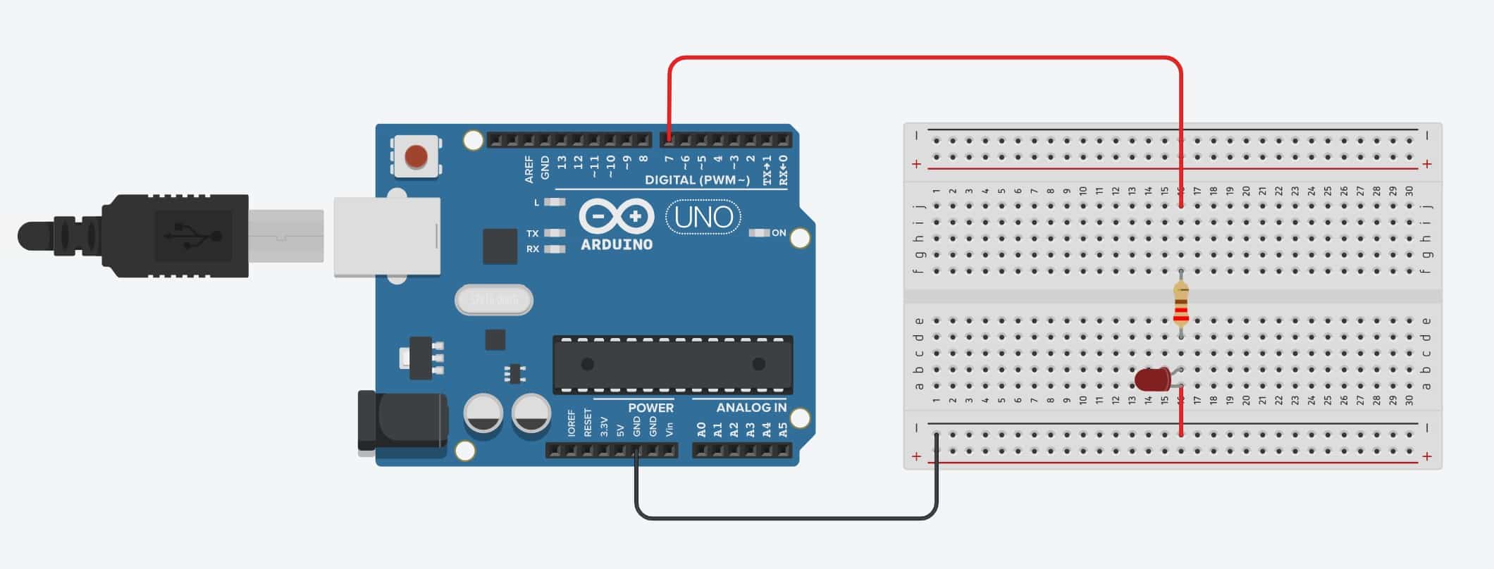
Blinking LED Test :
I am going to program a simple blinking project by using C language. This is the first time for me using this language.So excited to learn about it!
Let’s connect the components!
I will use the following components:
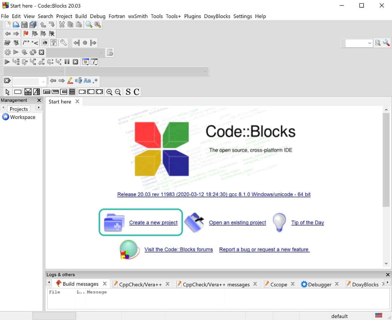
To start working on this software :
1. Click on create a new project.
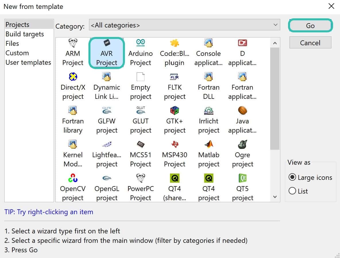
2. Then, Choose AVR Project > clicked Go.
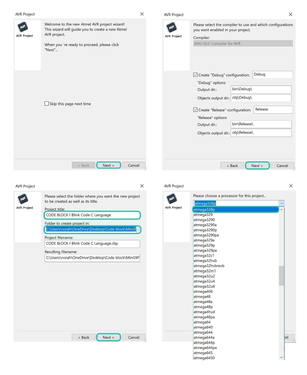
3. The next step a dialogue box is shown. Choose Next > Next > Then write the project title and folder to create project in > The last thing is to choose the processor choose Atmega328p to test the Arduino.
After that click on source and I select main. Then, write the code in the work space.
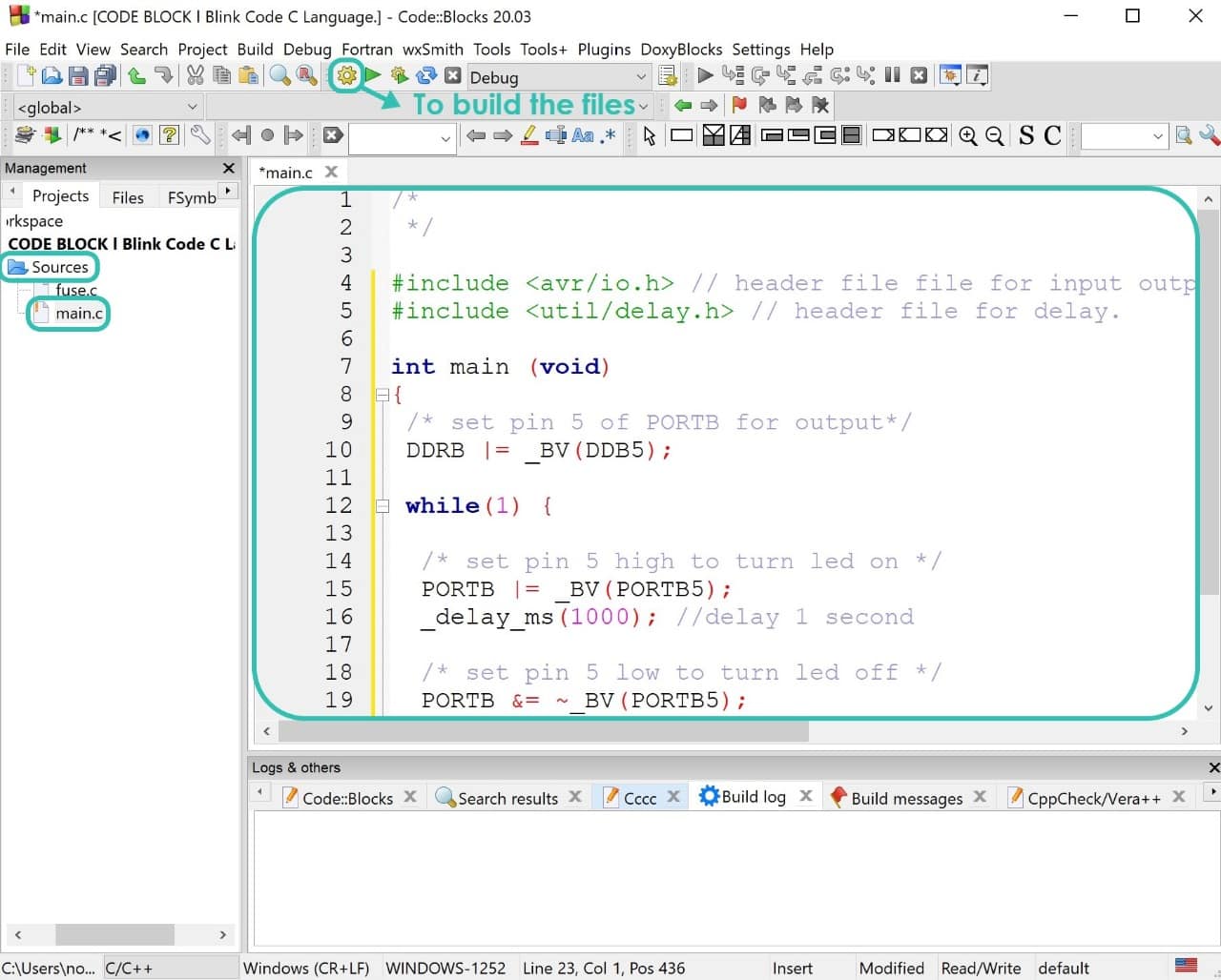
C Language Blink Code :
#include avr/io.h
#include util/delay.h
DDRB |= _BV(DDB5);
PORTB |= _BV(PORTB5);
_delay_ms(1000);
PORTB &= ~_BV(PORTB5);
_delay_ms(1000);
After I wrote the code, I clicked on the Build function which looks like a gear icon to compile and build all the necessary files. Then, I go to Tools in the menu bar and click on Arduino Builder.
What is Arduino Builder ?
It is a completely standalone compile line tool that allows users to compile their Arduino sketches and compiled ELF or HEX file to the Arduino Board.
To continue the process, I clicked on the Load sketch then I uploaded the hex file. And I go to Target and selected the Arduino Uno.
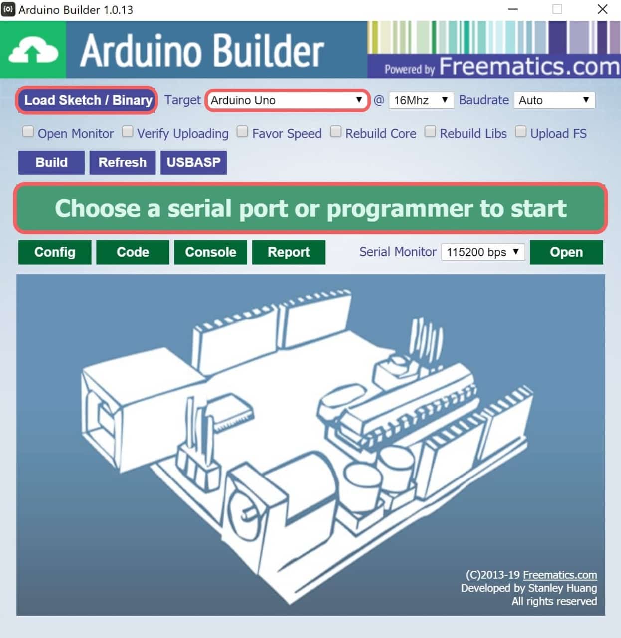
After that, I connected the Arduino to the computer and I chose the COM. As soon I chose the port the Arduino Builder started to program it.
Arduino Programming and Testing :
