New Challenge ! Let's Start
Computer-Aided Design
This assignment is a piece of cake!! Haha =)
In this assignment, we have to try different 2D drawing and 3D modeling softwares, in order to discover them and know the difference between parametric and nonparametric software. I think this assignment is easy for me because I am an interior designer and I have skills in different 2D and 3D parametric softwares. This week, I used some 2D/3D softwares that I am familiar with such as Inkscape, Autocad, and 3D MAX.
Wait! Let’s talk about the meaning of CAD.
What is computer-aided design (CAD) ?
Computer-aided design (CAD) refers to a process whereby computers are being used to assist in design process. Engineers, Architects, Designers, Artists and many more professionals use softwares to create drawings or technical illustrations.
I will talk about my experience as a designer with each software.
Autocad

I have been using Autocad software since 2012, when I was still in college. I like using this design software for 2d architectural drawings.It comes in handy when there is a need for details. I can also use Autocad to make 3D models, but I prefer not to use this software for 3D modeling.
What is Autocad Software ?
Autocad is a drafting software tool that allows a user to conceptualize ideas, product designs and drawings.
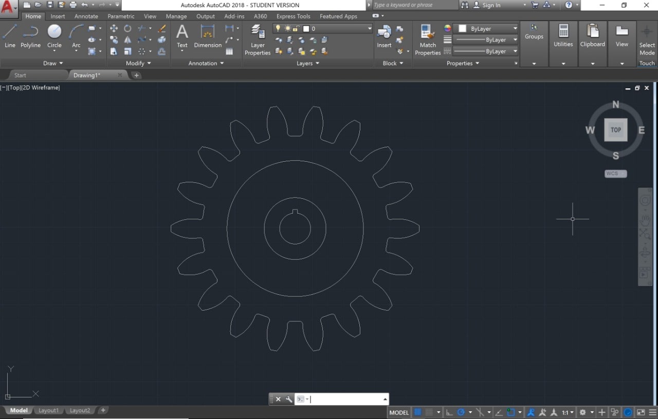
This is the interface of Autocad.
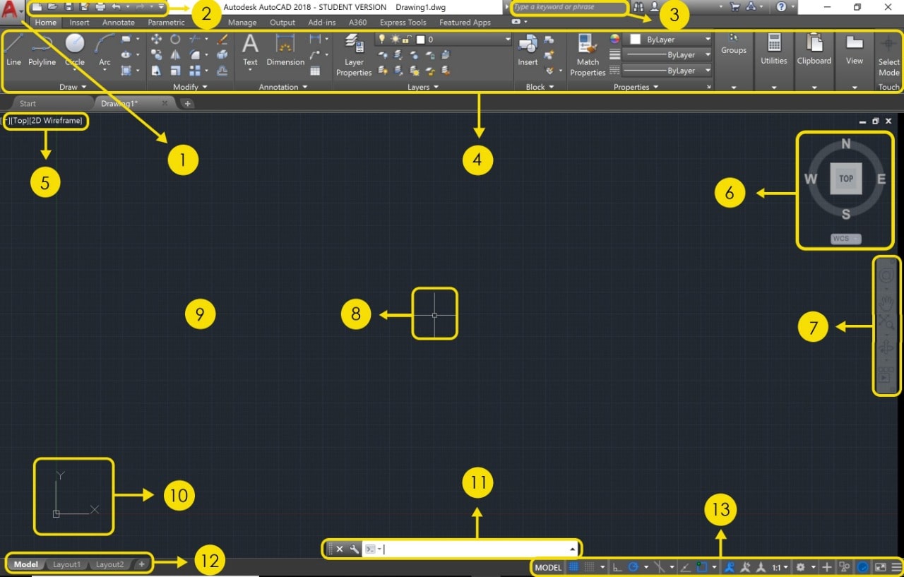
The Main Parts :
- 1. Application menu.
- 2. Quick access toolbar.
- 3. Search bar.
- 4. Ribbon bar.
- 5. Viewport control.
- 6. World coordinate system.
- 7. Navigation bar.
- 8. Cross Hairs.
- 9. Workspace.
- 10. User coordinate system (UCS Icon).
- 11. Command window.
- 12. Layout tabs.
- 13. Status bar.
I am going to draw gears by using the different features available on this software.
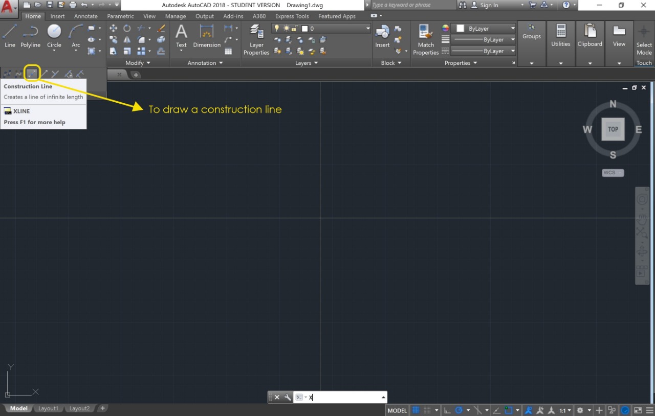
How to draw gears in Autocad?
1. Draw a construction line.
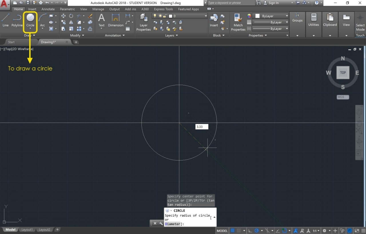
2. Draw a circle.
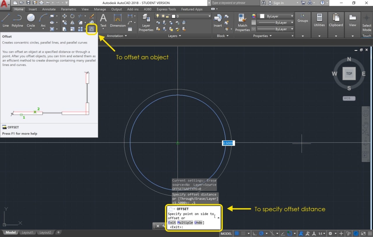
3. Use offset to make another circles and lines with different dimensions.
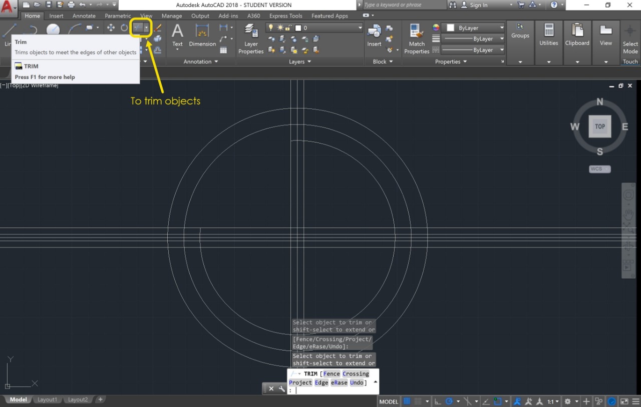
4. Use trim to remove some parts.
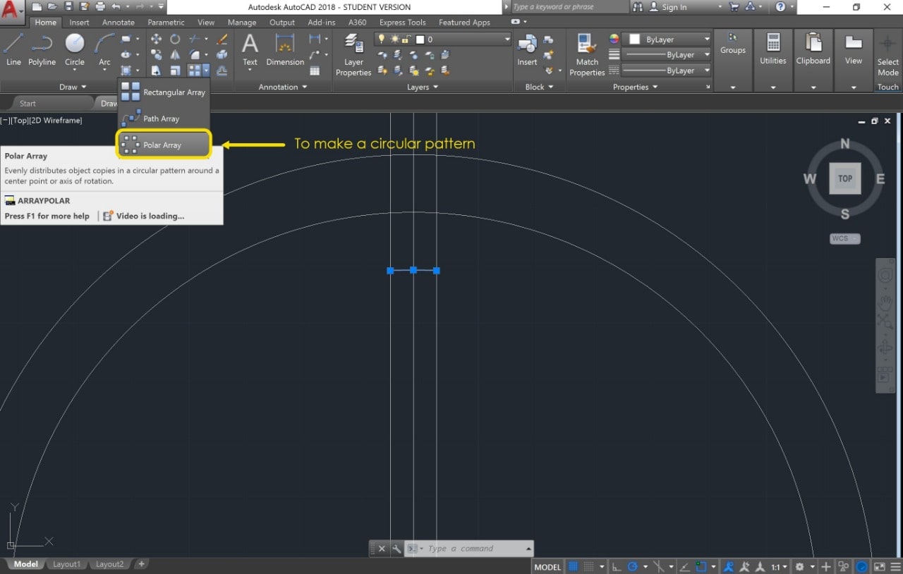
5. Use polar array to copy the object in a circular pattern.
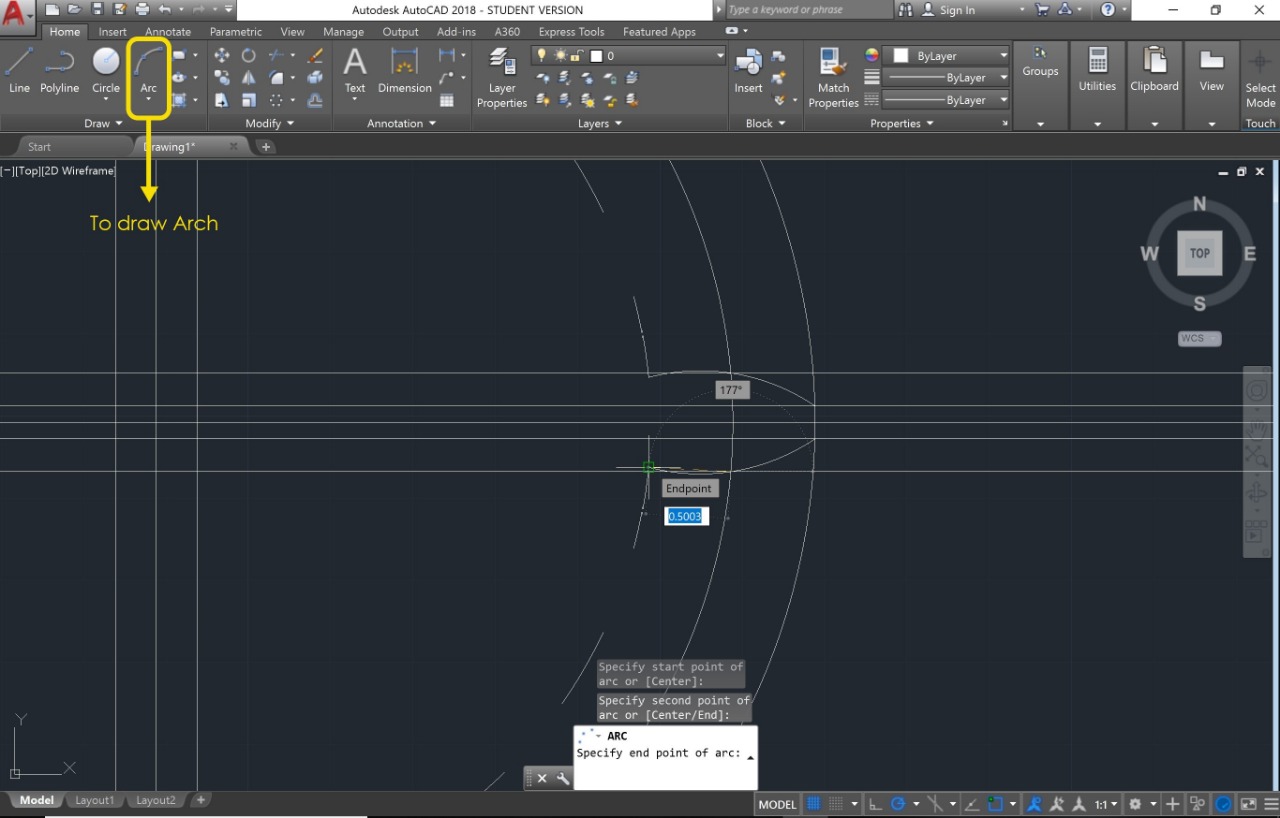
6. Use Arch to make the teeth.
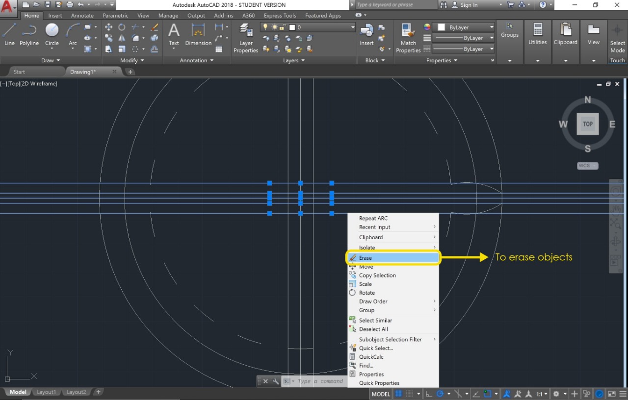
7. Erase all the lines.
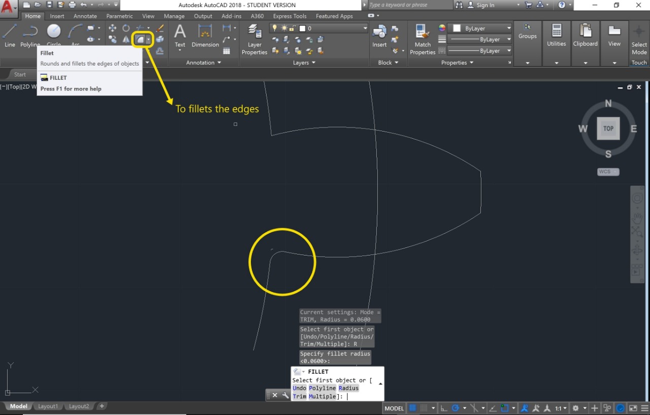
7. Use fillet to make the angle smooth.
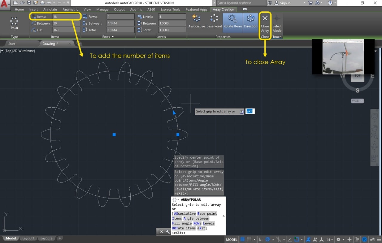
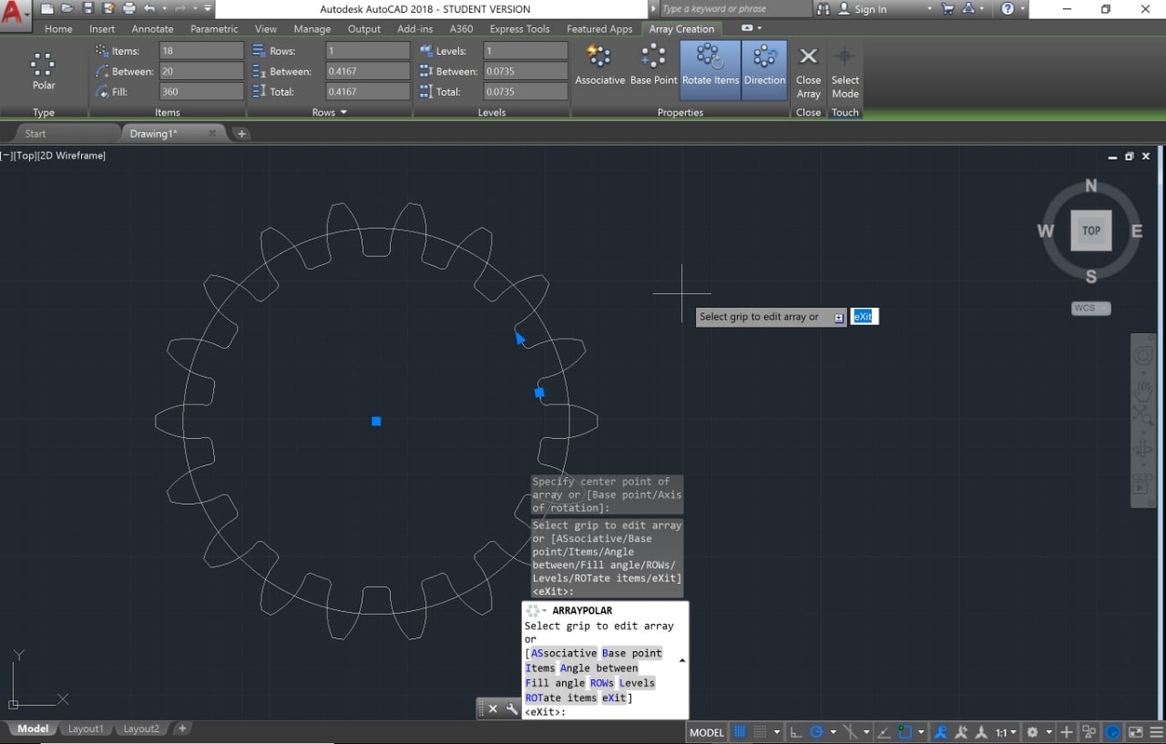
8. Use Array to copy the teeth in a circular pattern.
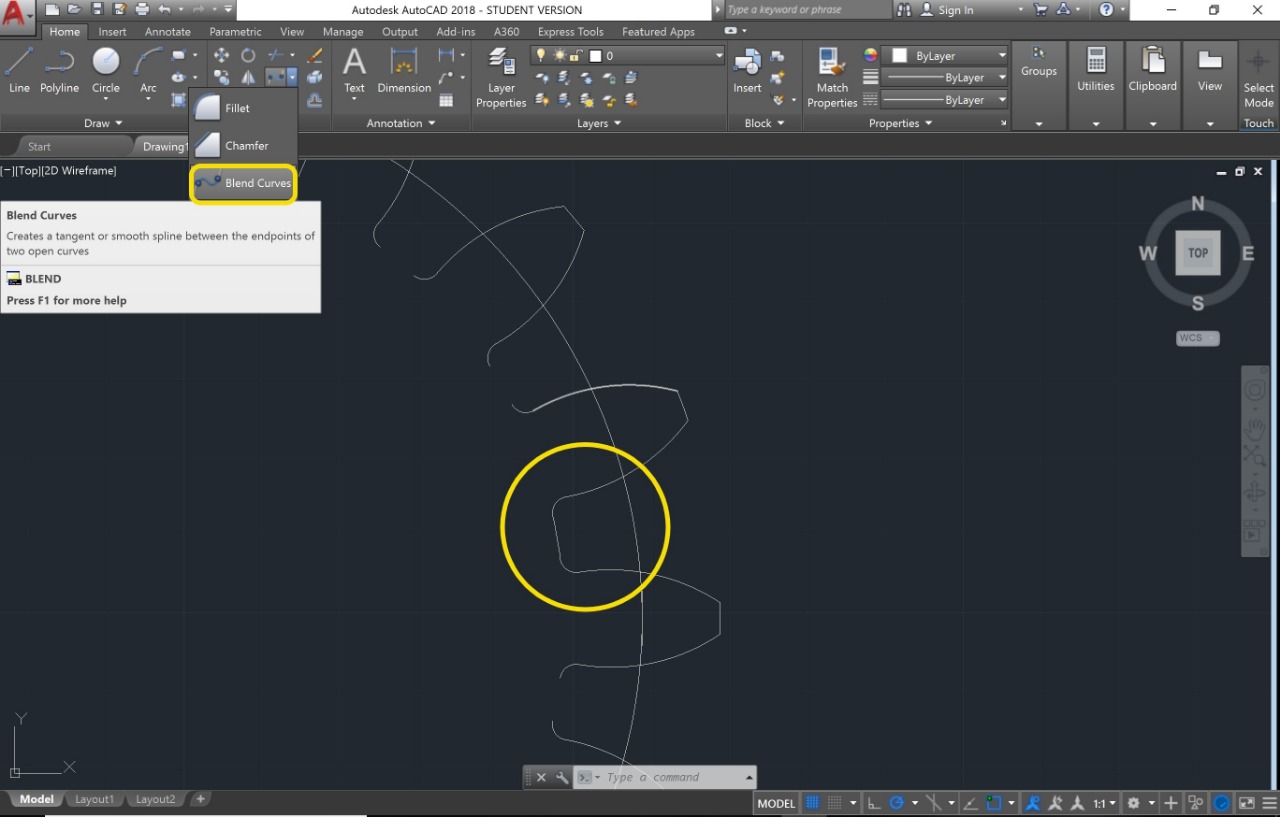
9. Use blend Curve to make spline between the endpoints of two open curves.Then use array to make it in all of the others.
10. Draw the 3 circles and some details inside the object.
11. Adding the dimensions.
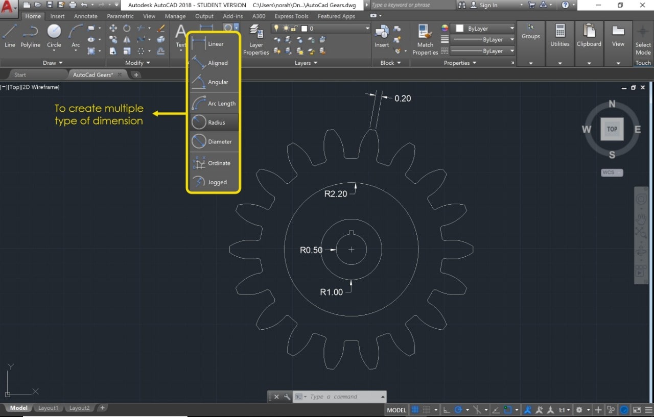
Inkscape

Inkscape is an open source software which I use regularly. This software is one of the easiest design software that you can use! The main feature of inkscape which I admire most is trace Bitmap. Searching for high resolution photos has always been a nightmare, but with Inkscape, it has become exceptionally easy! HOW?
This software allows you to convert the photos from raster to vector by using trace bitmap.
This is the interface of Inkscape.
The Inkscape interface consists of elements designed to make work simple, harmonious and contextual. It is principally made of a single window in which one creates and manipulates drawings.
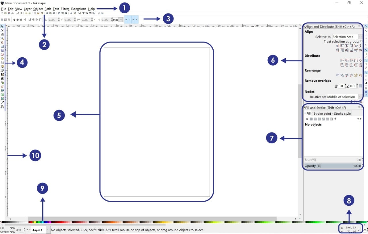
The major areas :
- 1. The Menu Bar.
- 2. The Commands Bar.
- 3. The Tool Controls Bar.
- 4. The Toolbox.
- 5. The Canvas.
- 6. Alignments and distribution.
- 7. Fill and stroke.
- 8. The Status Bar.
- 9. The Color Palette.
- 10. The Rulers, Guides and Grids.
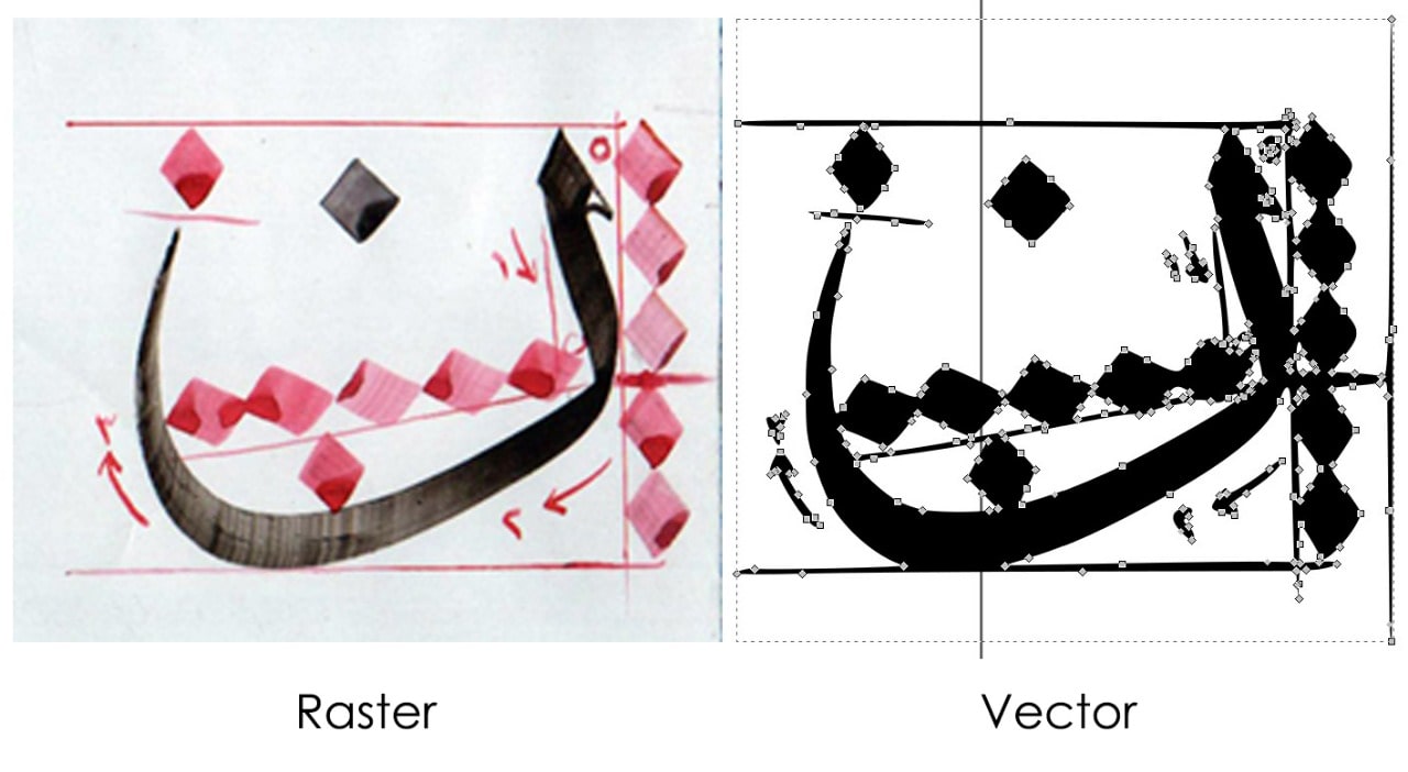
What is the meaning of raster and vector ?

Raster : The photos are composed of pixels. When you zoom into on the photo, it will not be clear
Vector : The photos are composed of paths. When you zoom into the photo, its quality will not change. It should be clear.
How do you trace the photos ?
To trace the photos from raster to vector you should follow the steps:
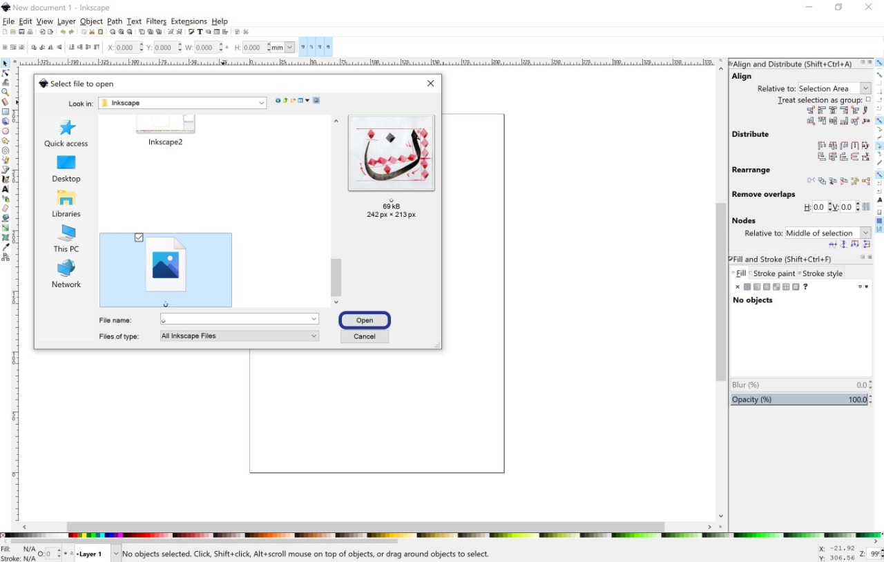
- 1. Open Inkscape
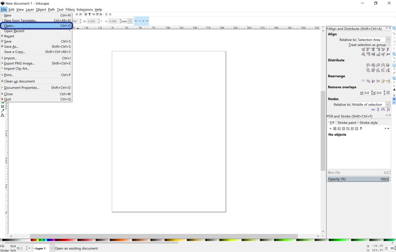
2. Go to file > import any photo that you like. I love Arabic calligraphy so I decided to choose a photo with the first letter of my name written by hand. It is called ( Noon - ن ).
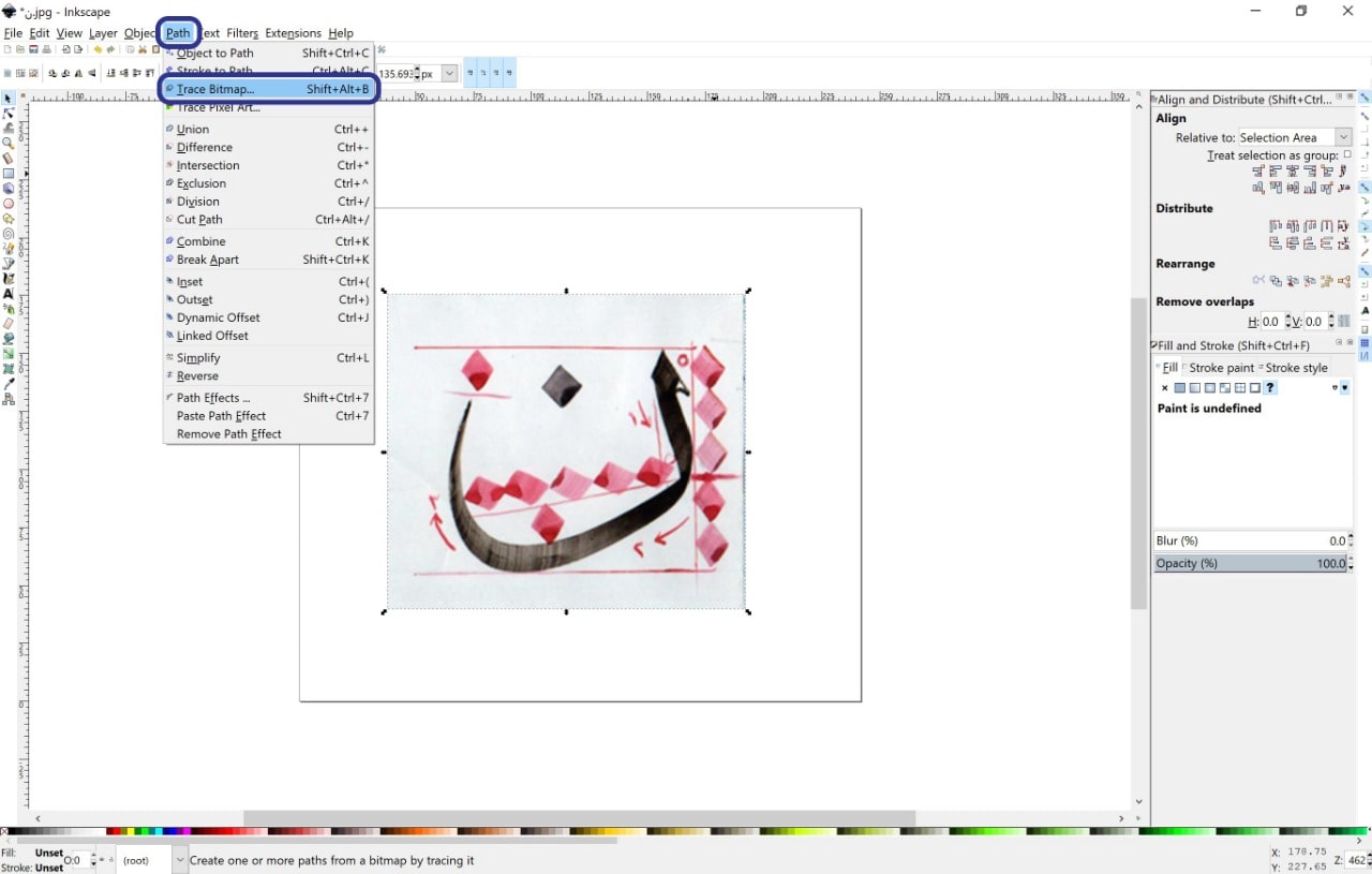
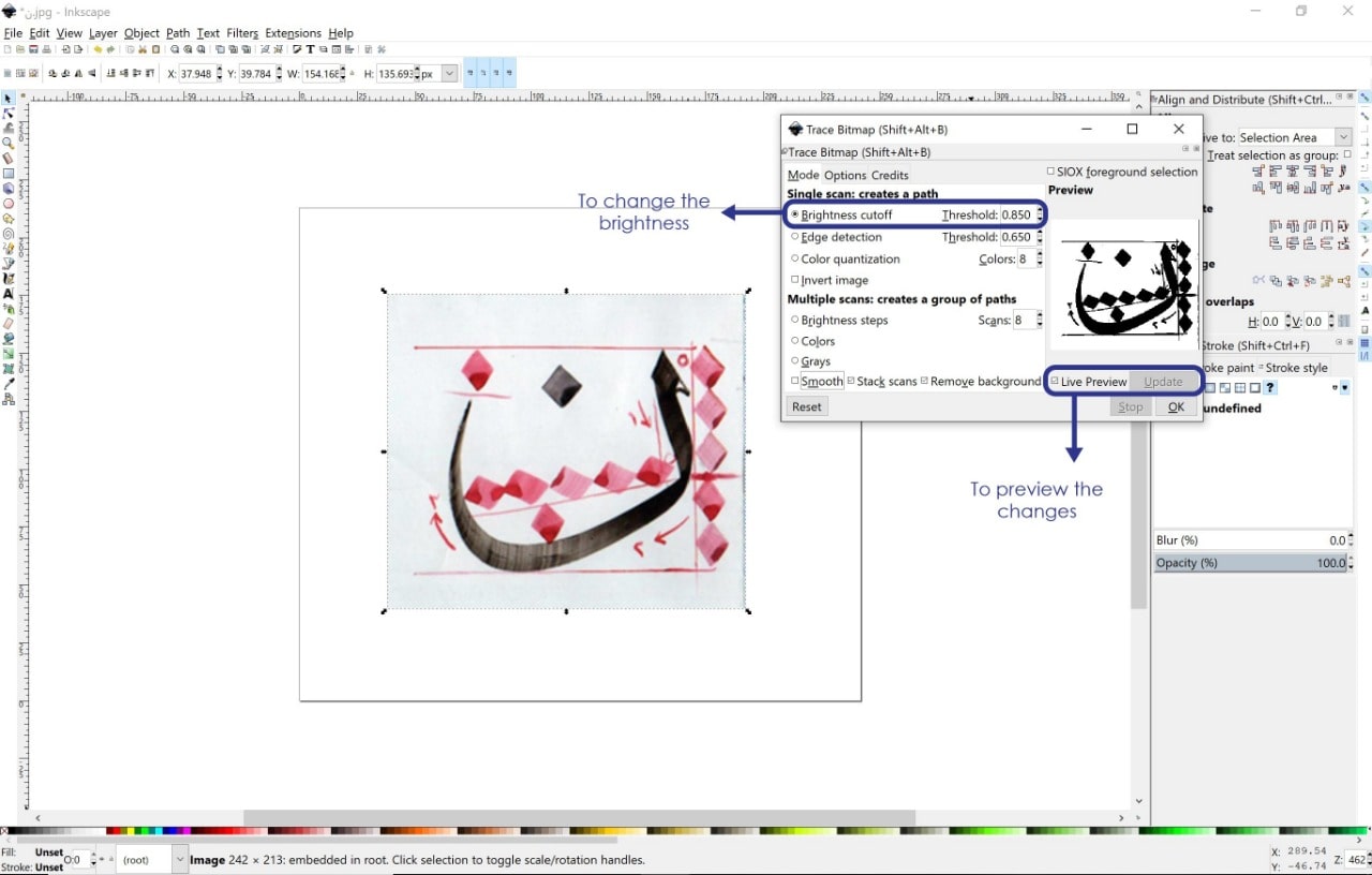
3. Select the photo > Go to Path > Trace Bitmap > Ok.
The result!
3D Max

I have learned 3D Max software since 2013. It has many different features that enables you to make amazing models in the easiest way. One of the most important aspects of using 3ds Max is its versatility.
What is 3D Max ?
3D Max is a professional 3D computer graphics program for making 3D animations, models, games and images.
This is the interface of the 3D Max :
The Main Parts:
- 1. User Account menu.
- 2. Workspace selector.
- 3. Menu bar.
- 4. Main toolbar.
- 5. Ribbon.
- 6. Scene Explorer.
- 7. Viewport Layouts.
- 8. Command panel.
- 9. Viewports.
- 10. MAXScript Mini Listener.
- 11. Status line and Prompt line.
- 12. Isolate Selection toggle and Selection Lock toggle.
- 13. Coordinate display.
- 14. Animation and Time controls.
- 15. Viewport Navigation controls.
- 16. Projects toolbar.
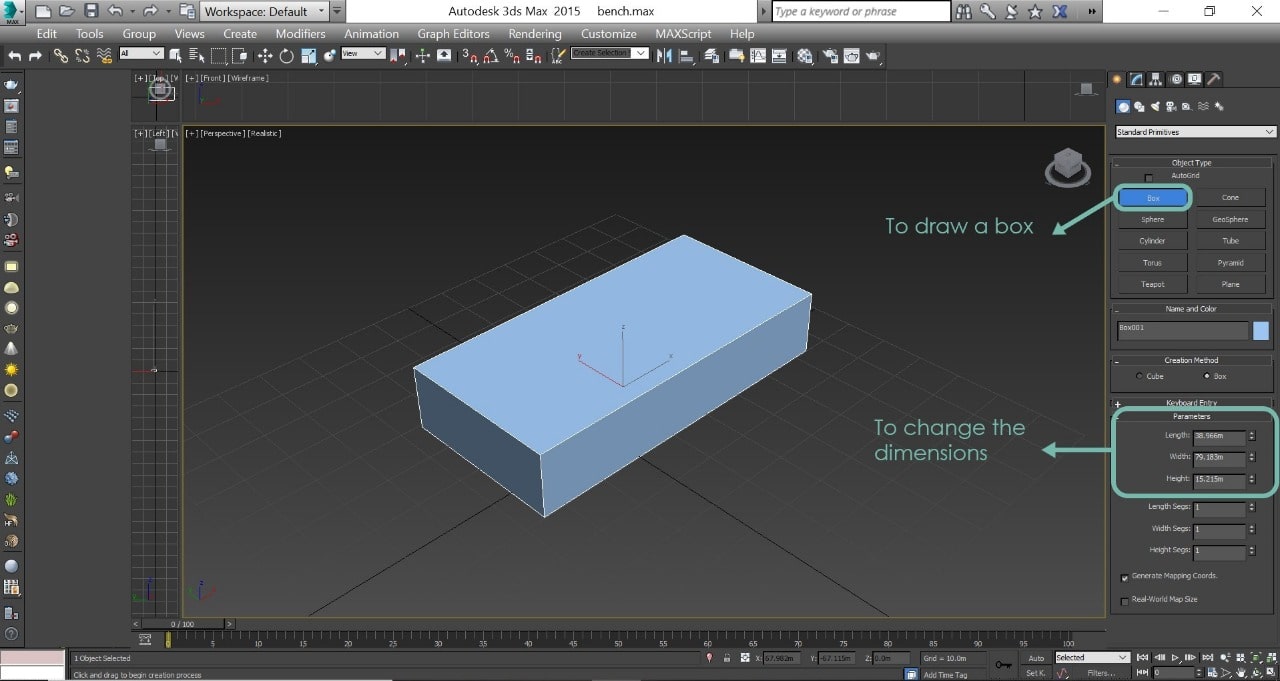
I will try to design an organic bench by using some features in this software
1. Draw a box
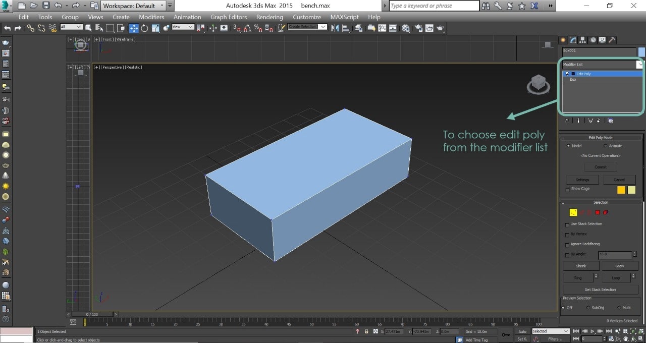
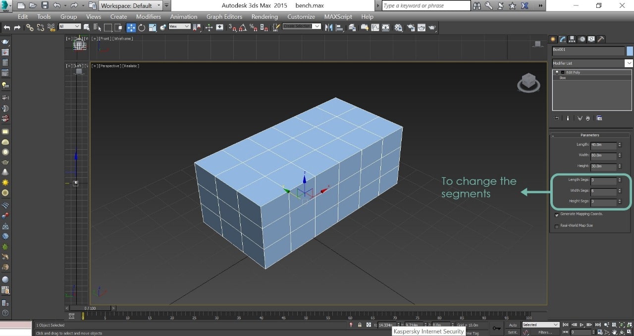
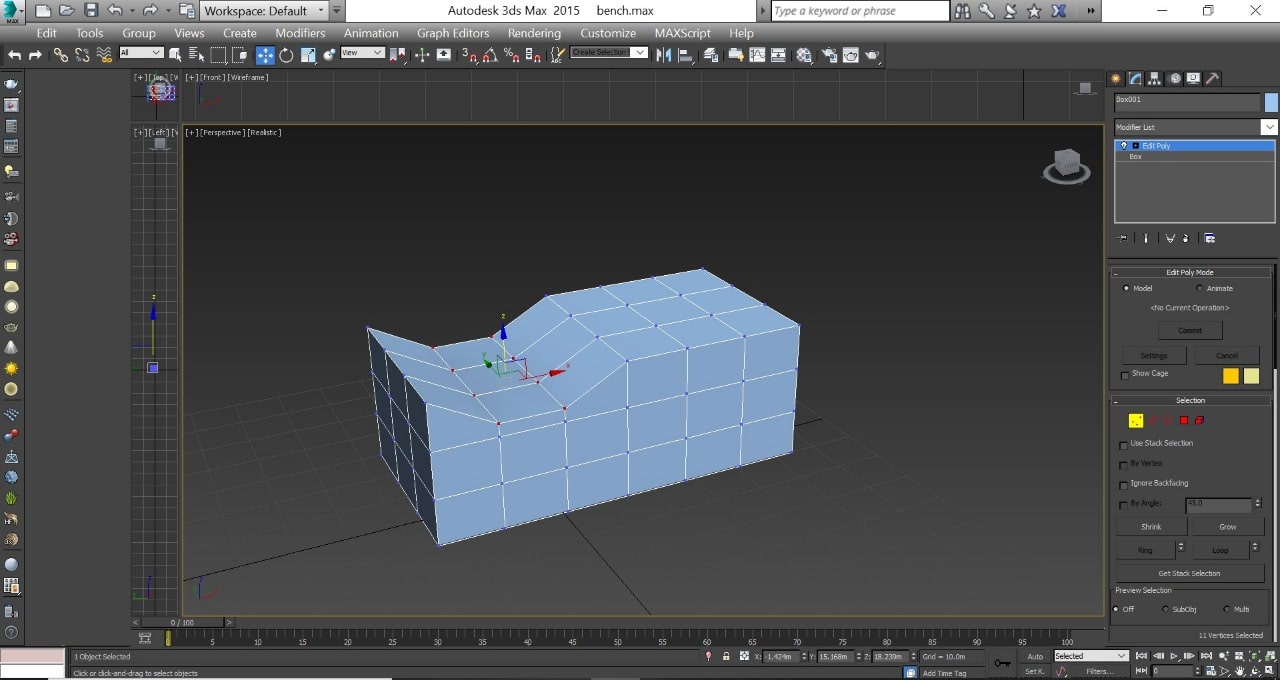
2. Choose edit poly from the modifier > Increase the number of segments > Reshape the object but using the vertex.
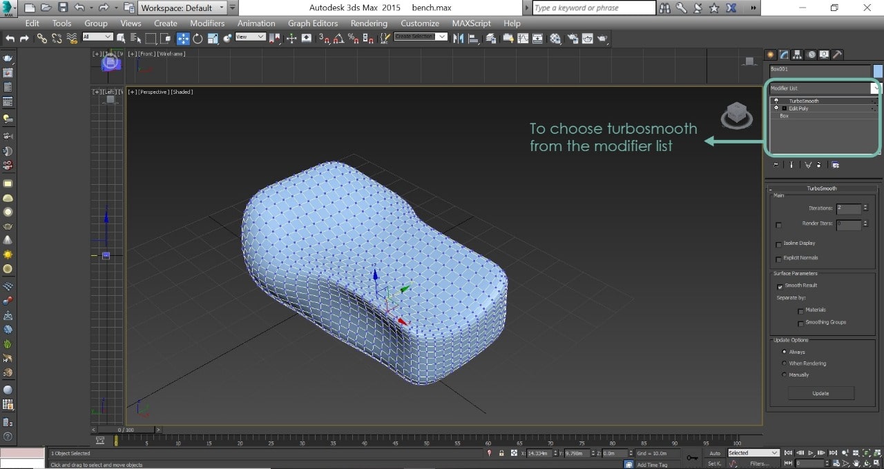
3. Make the object smooth by using Turbosmooth.
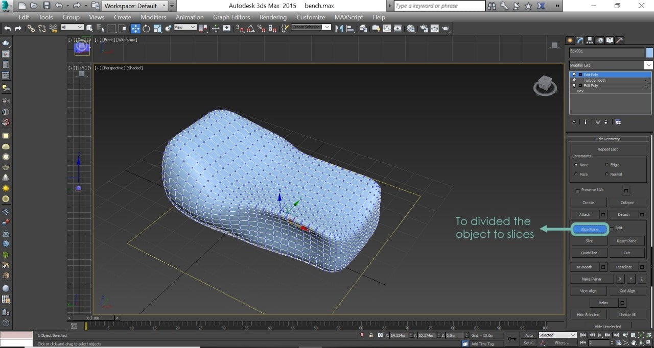
4. Divide the object manually into slices by using edit poly and then slice plane.
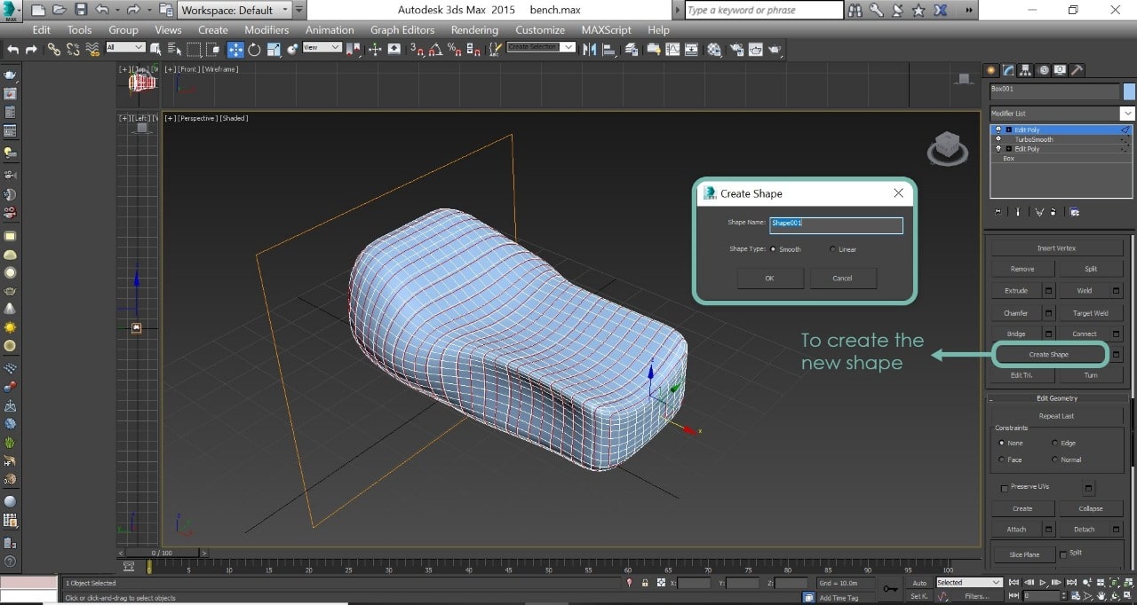
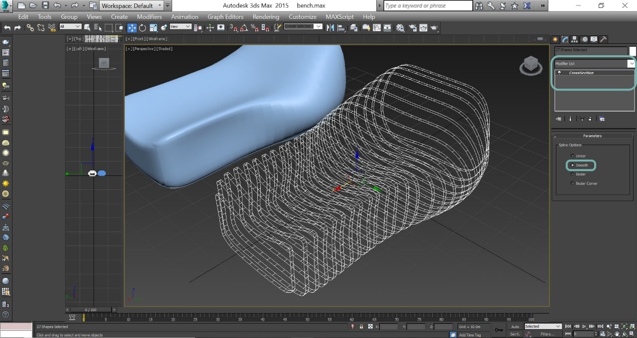
5. To make each slice become a new shape, choose create shape (smooth), and then move it.
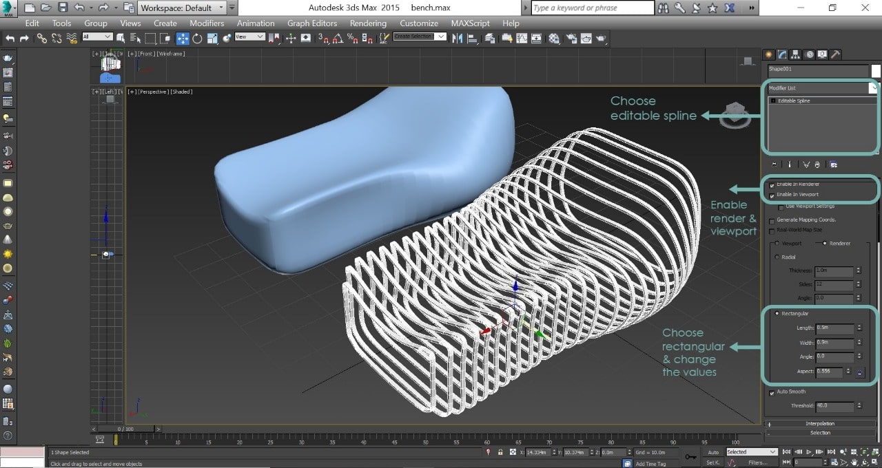
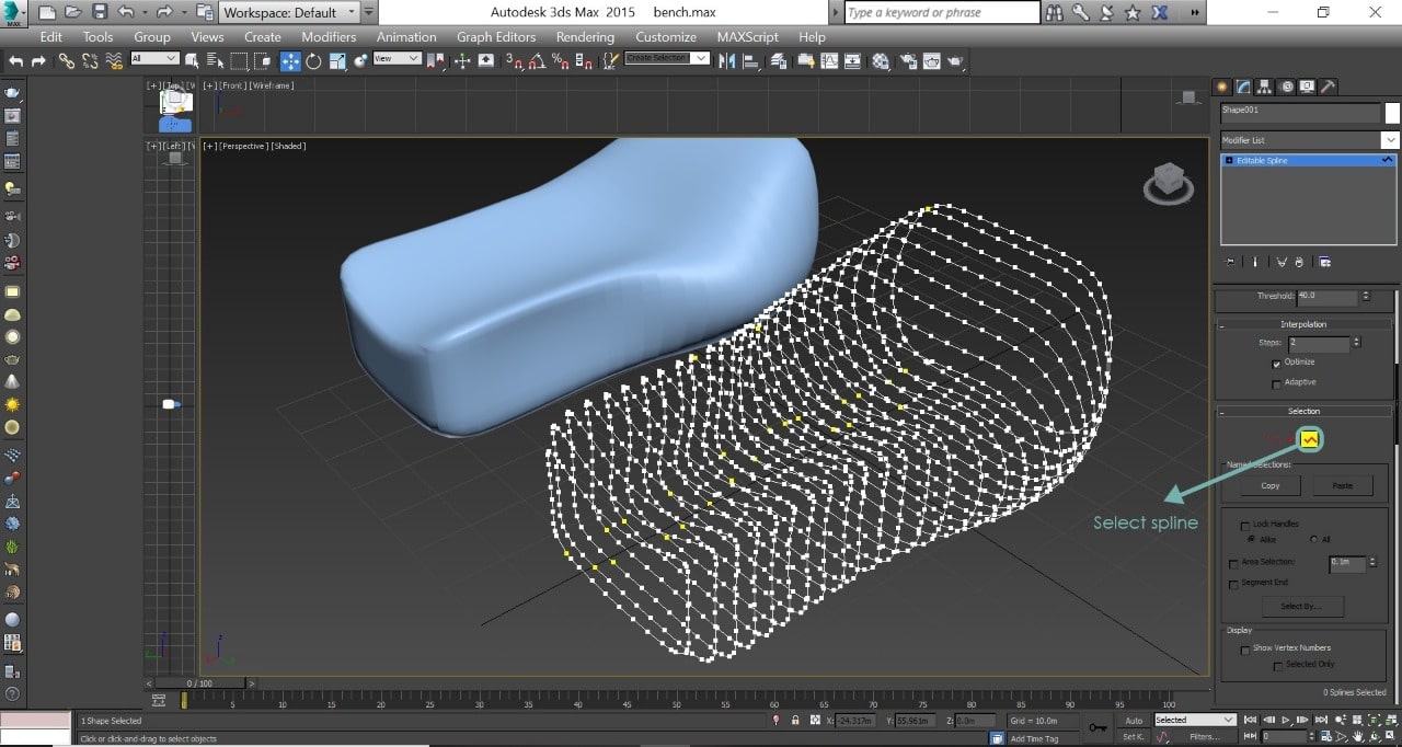
6. To make the slices become thicker choose editable spline > then enable rendering and view port > Choose rectangular look and change the values as you like.
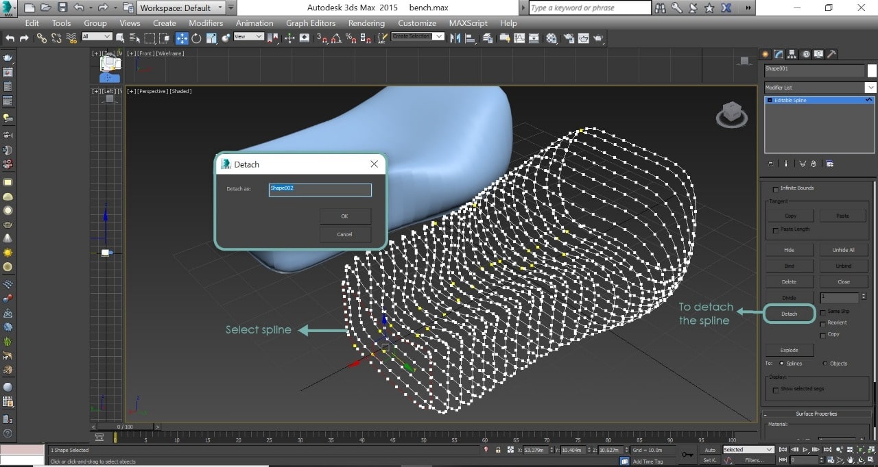
7. Select spline selection > Select each spline part > Press on detach to detach each separate spline.
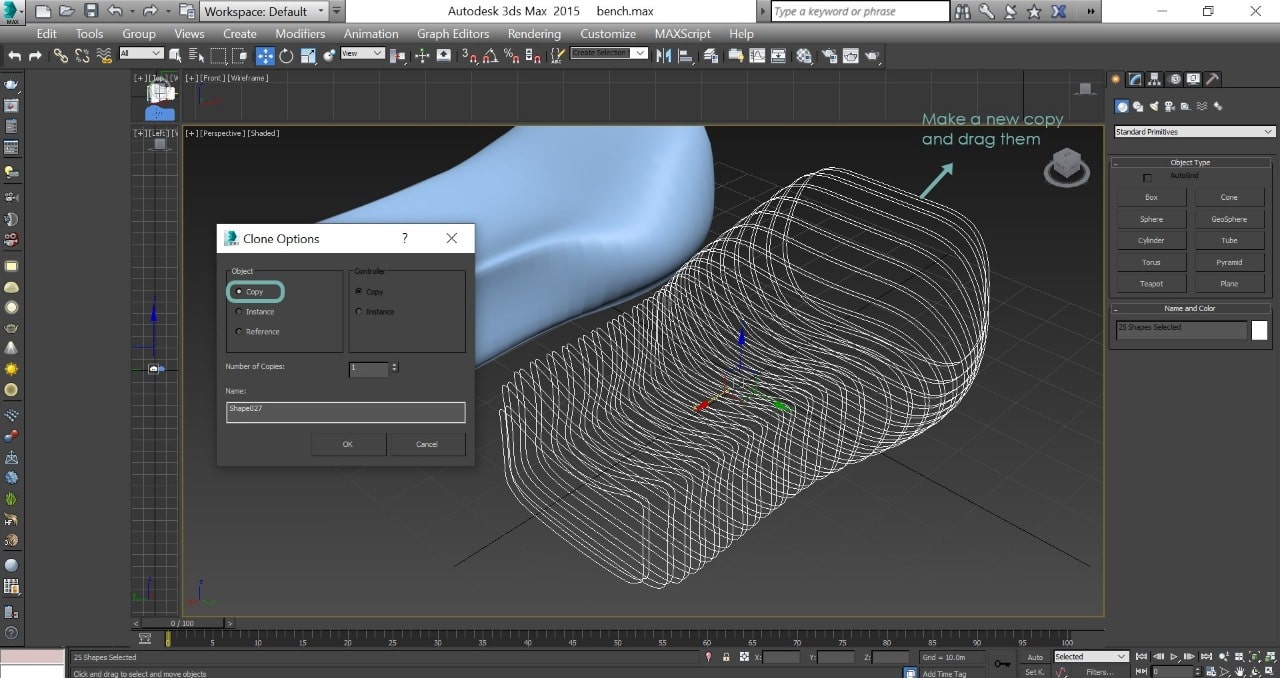
8. Select all the spline parts > Make a new copy and drag them.
`
9. Select one spline > Then attach it to the spline that is next to it.
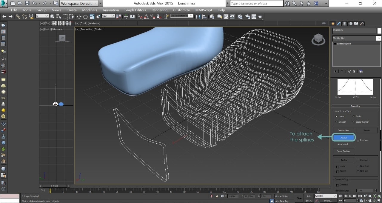
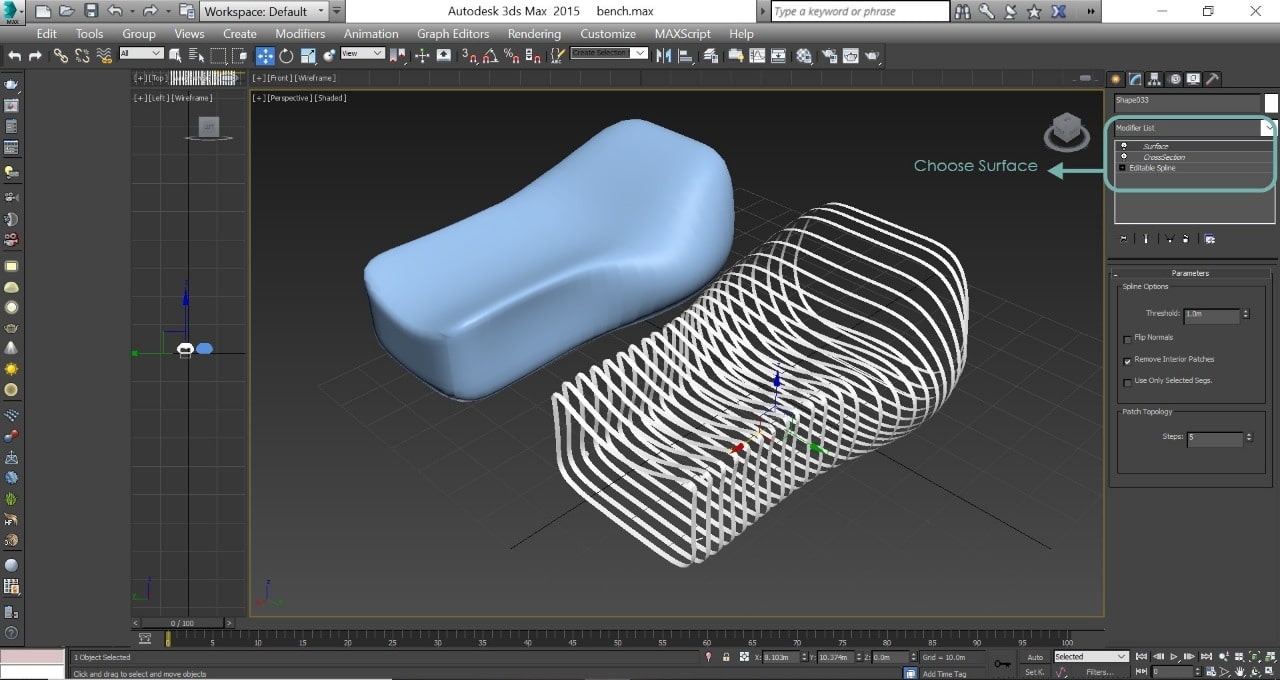
10. To form a geometry with the lines > Select all the lines > Go to modifier list > Choose cross section > Go to modifiable list > Choose surfers.
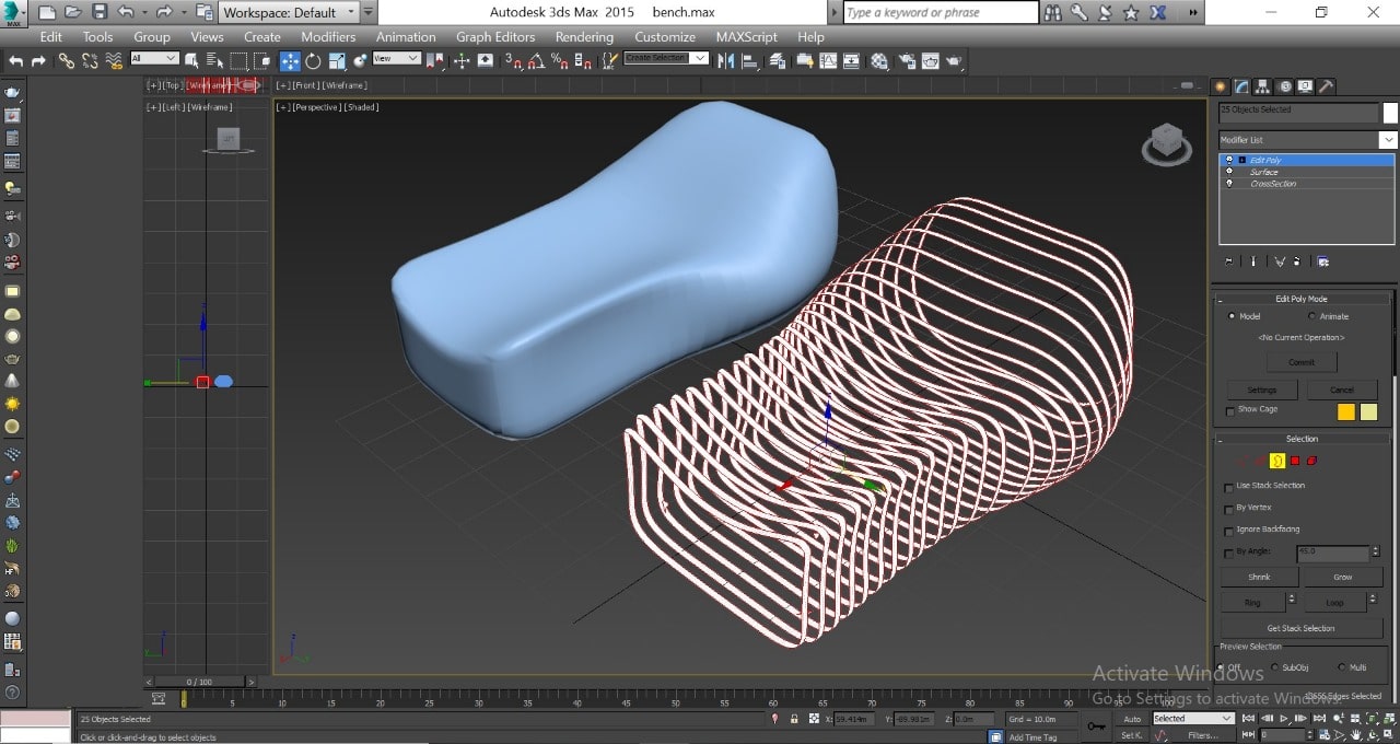
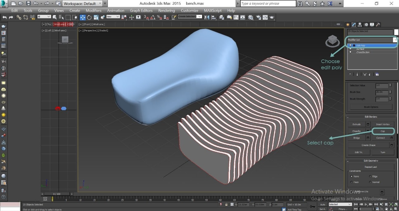
11. To cap off the objects > Select all the objects > Go to modifier list > Choose edit poly > Select all the objects > Click on cap.
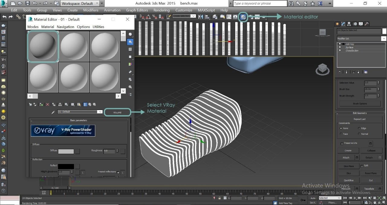
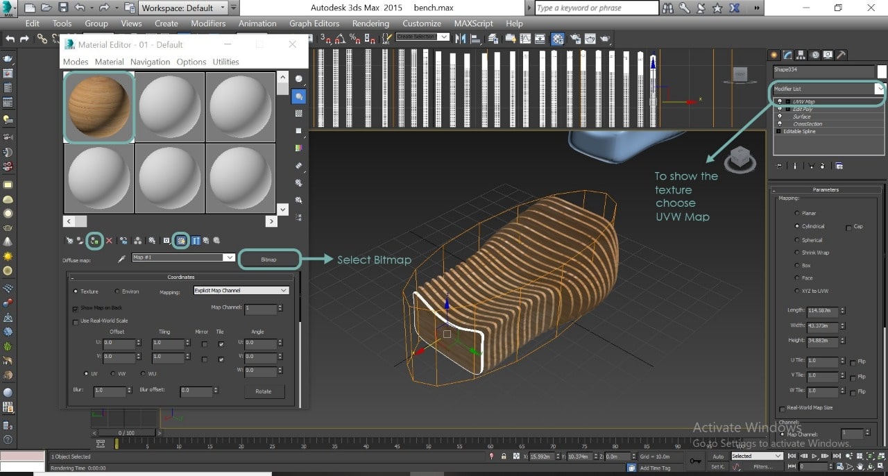
12. To add texture to the object > Go to material editor > Go to bitmap and choose wood material from the material list that you have > Assign the material > Go to modifier list > UVW map to show the texture.
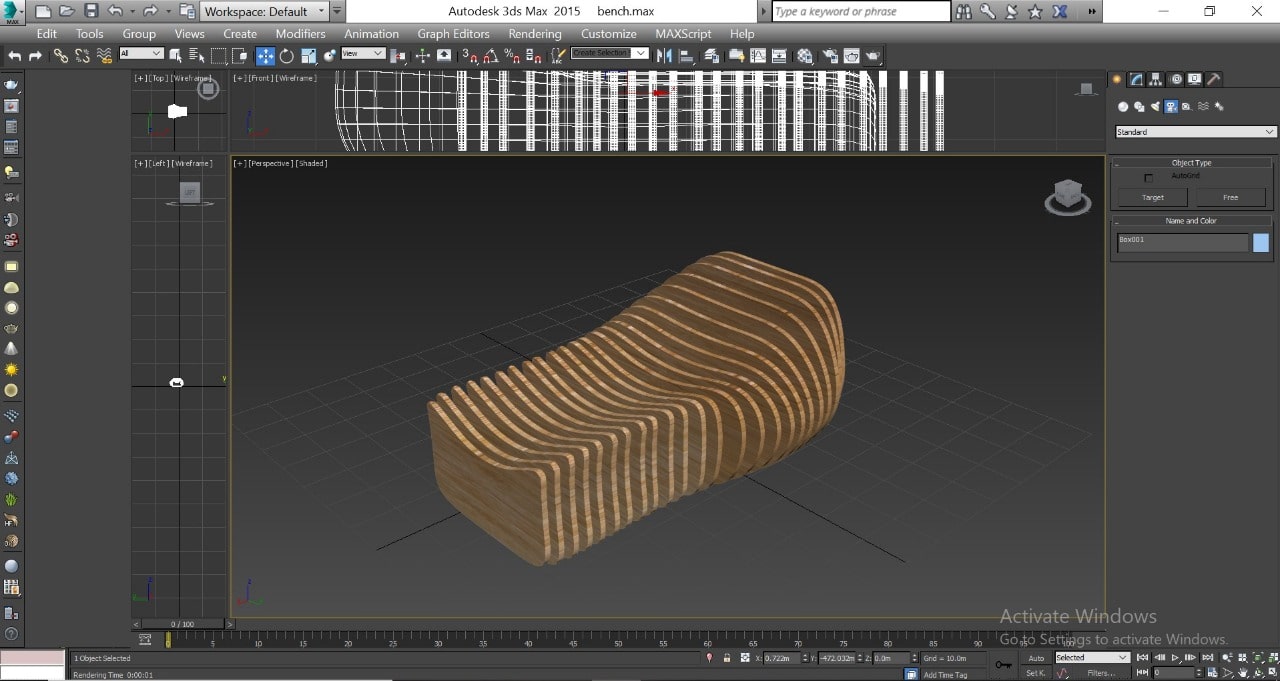
The final look !
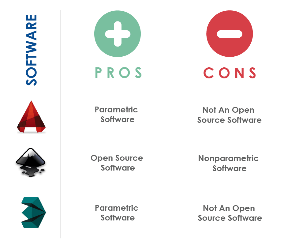
After suing these softwares, I've listed some advantages and disadvantages which can help in choosing the best design software that I can be used in completing FAB Academy assignments.
I have decided not to use any of the above softwares as the main design software in FAB Academy, and this is because I want to learn a new design software called On Shape.

Why On Shape?
Below is the user interface of Onshape :
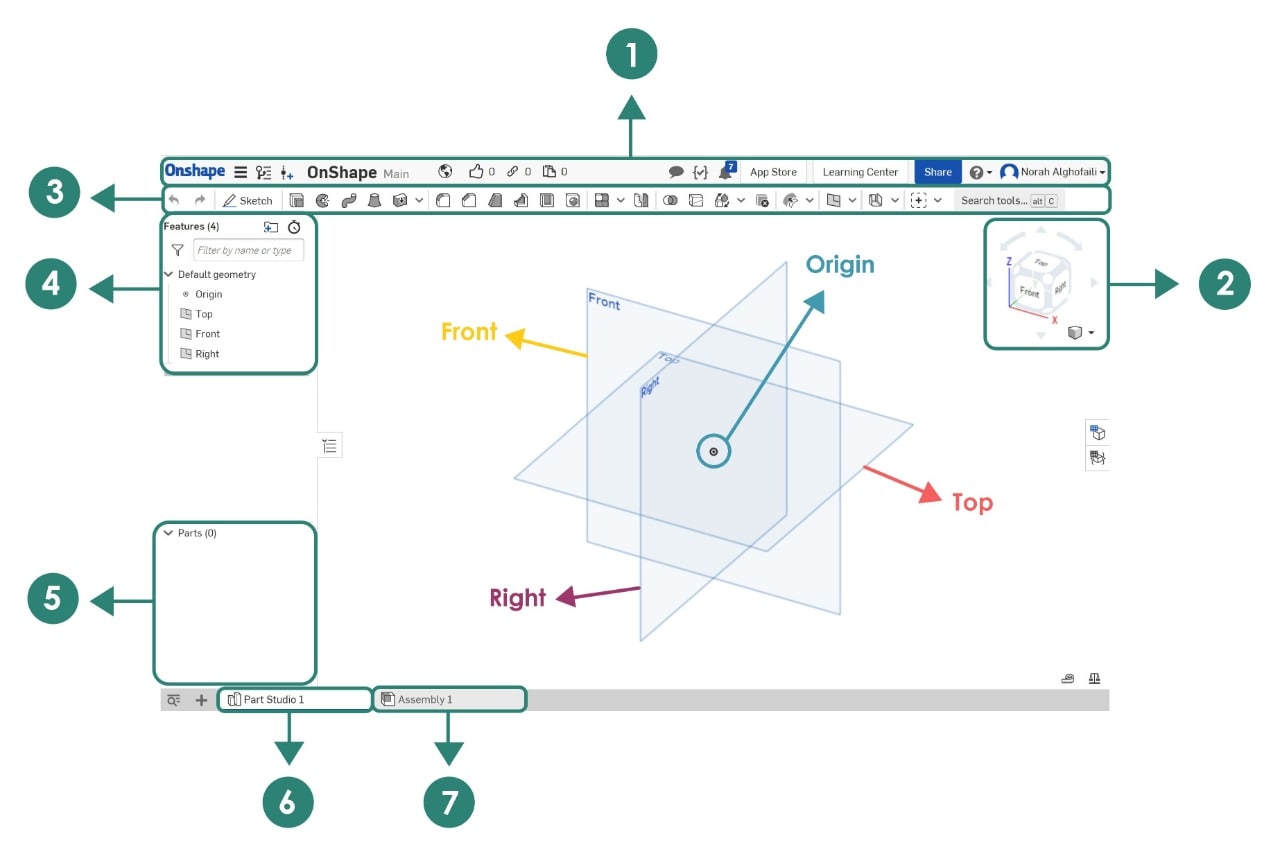
The Main Parts:
- 1. The User Document Menu : This contains some commands such as ( Rename a document, Document properties, Copy workspace ... etc)
- 2. The View Cube : This helps us rotate and view our model.
- 3. The Tool Bar : This shows us the available commands feature creation tools and is context-sensitive.
- 4. The Feature List : Features are used to create CAD geometry and
this list shows the order in which they were created.
- 5. The Part List : This is where parts are listed, in chronological order,
as they are created.
- 6. The Part Studio Page : It enables users to draw objects and use all the features available.
- 7. The Assembly Page : It enables us to assemble all the parts together.
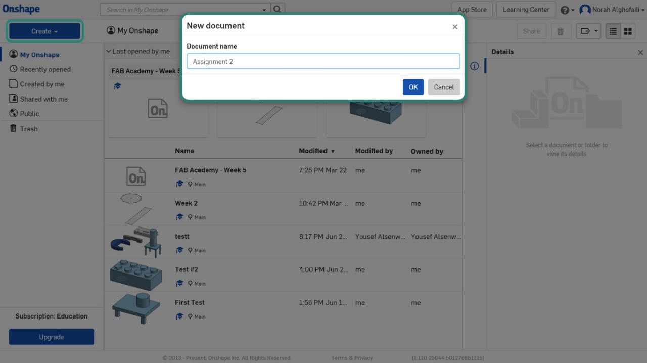
Let's start with the part studio page !
1. Open a new document by clicking on create then rename it.
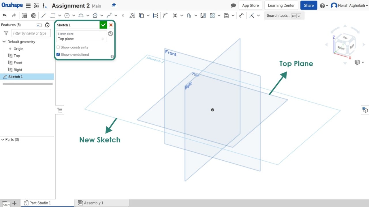
2. Click on sketch and chose the plane. I chose the top plane.
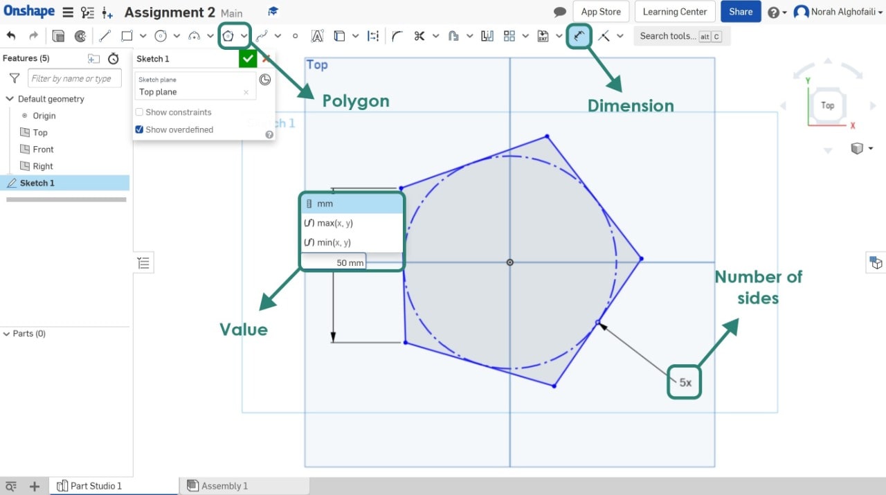
3. Use Inscribed Polygon to draw the shape then make it with 5 sides and change the dimension.
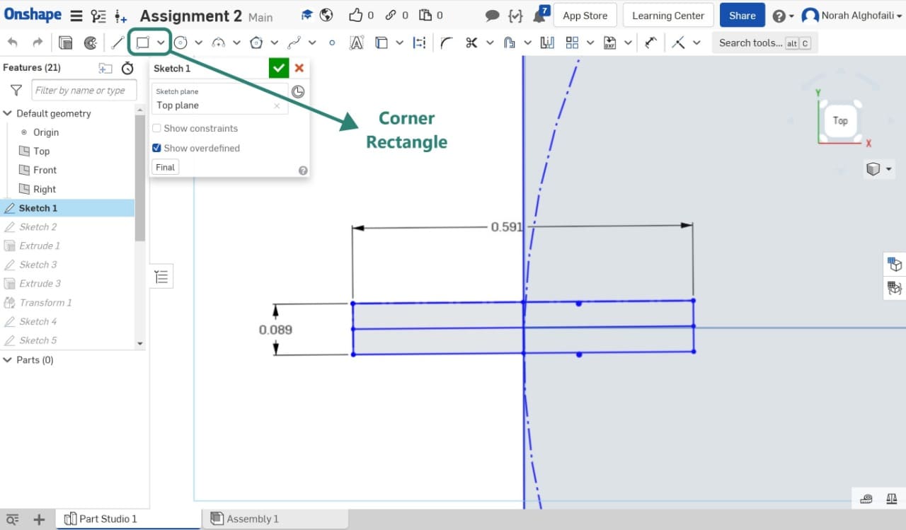
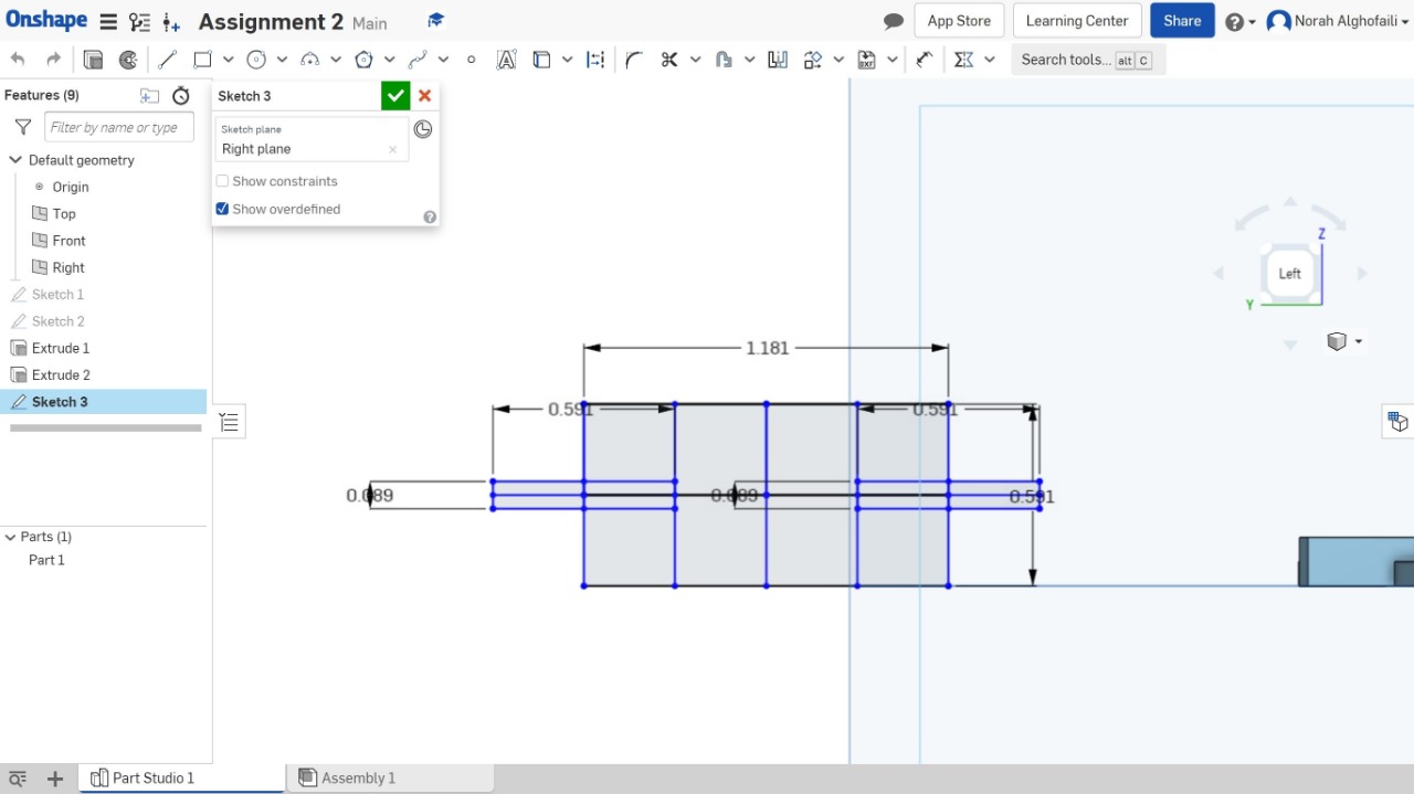
4. Use corner rectangle to draw the joints, and change the dimension.
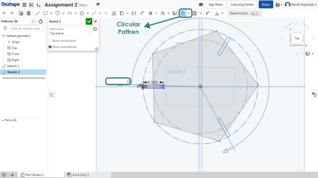
5. Use circular pattern to make 5 copies around the shape.
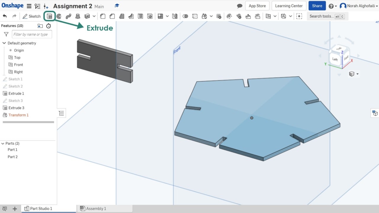
6. Make the shape a 3d object by using the extrude feature, and then remove some parts from the object.
7. Draw the joint by using rectangular, and then remove some parts.
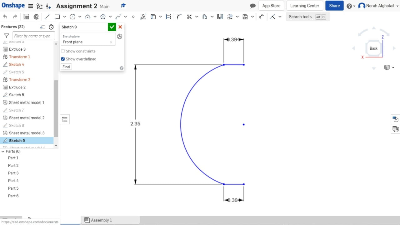
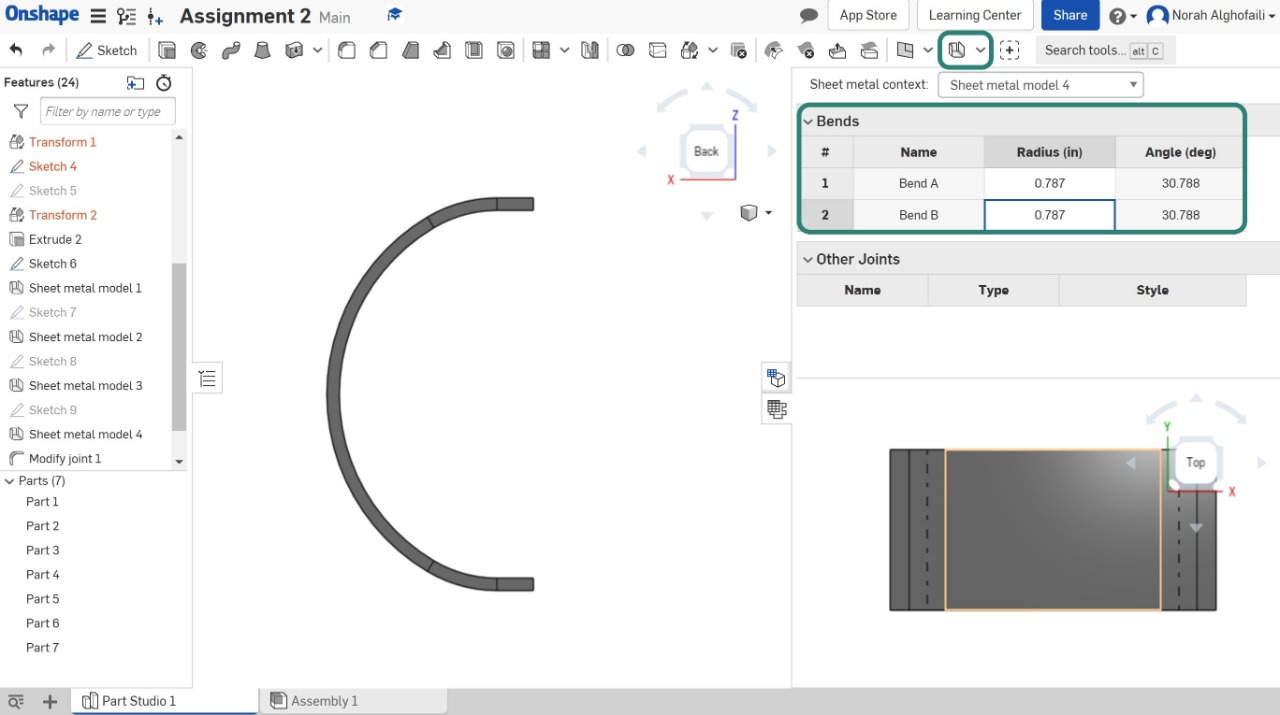
8. Draw the curve by using 3 points curve, and then extrude the object. Use ‘metal table’ and ‘flat view’ to make the object smoother by changing the radius.
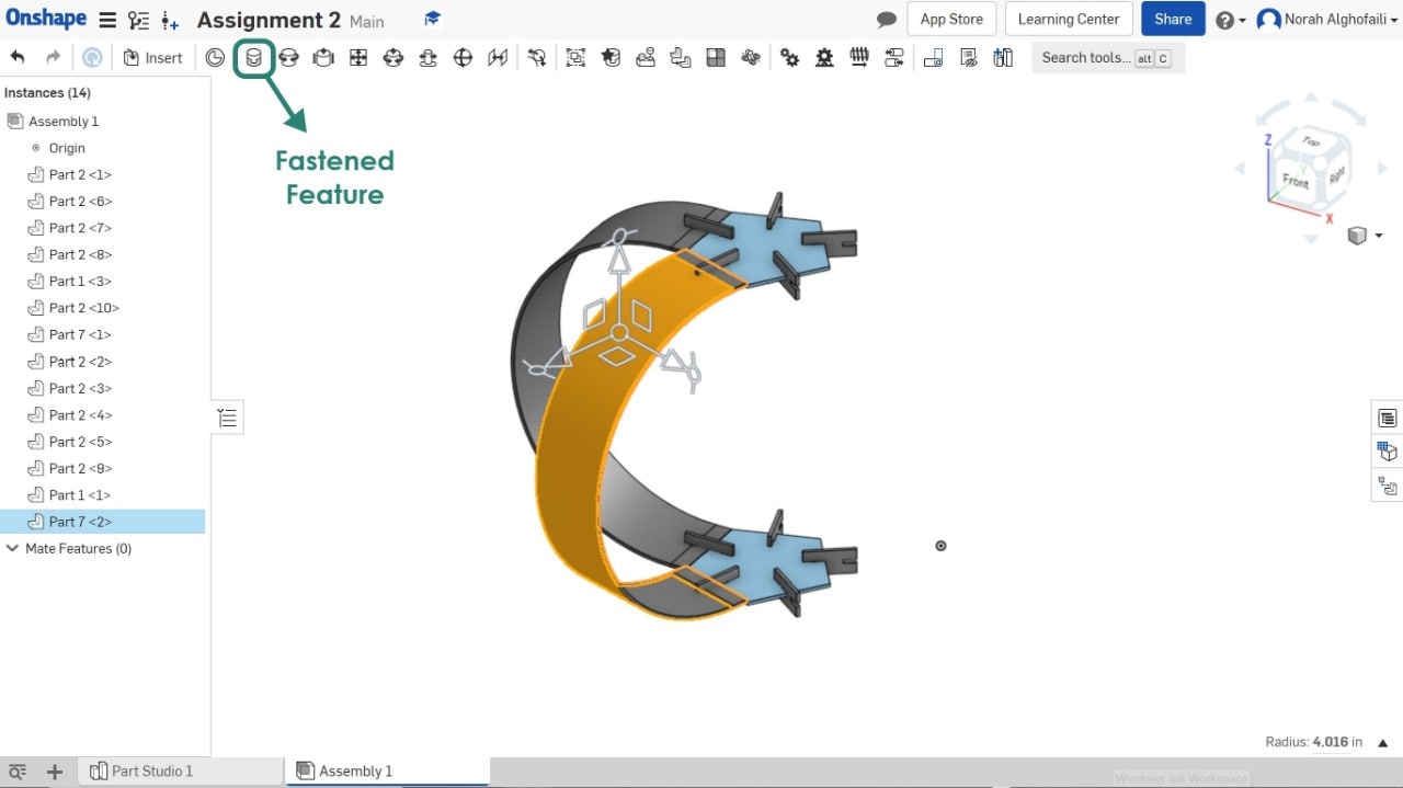
Let's assemble the object !
After opening the assembly page, click on insert to add parts.
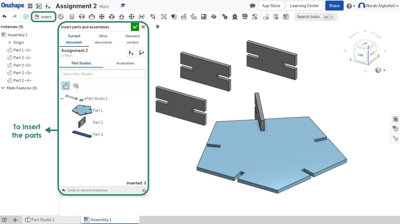
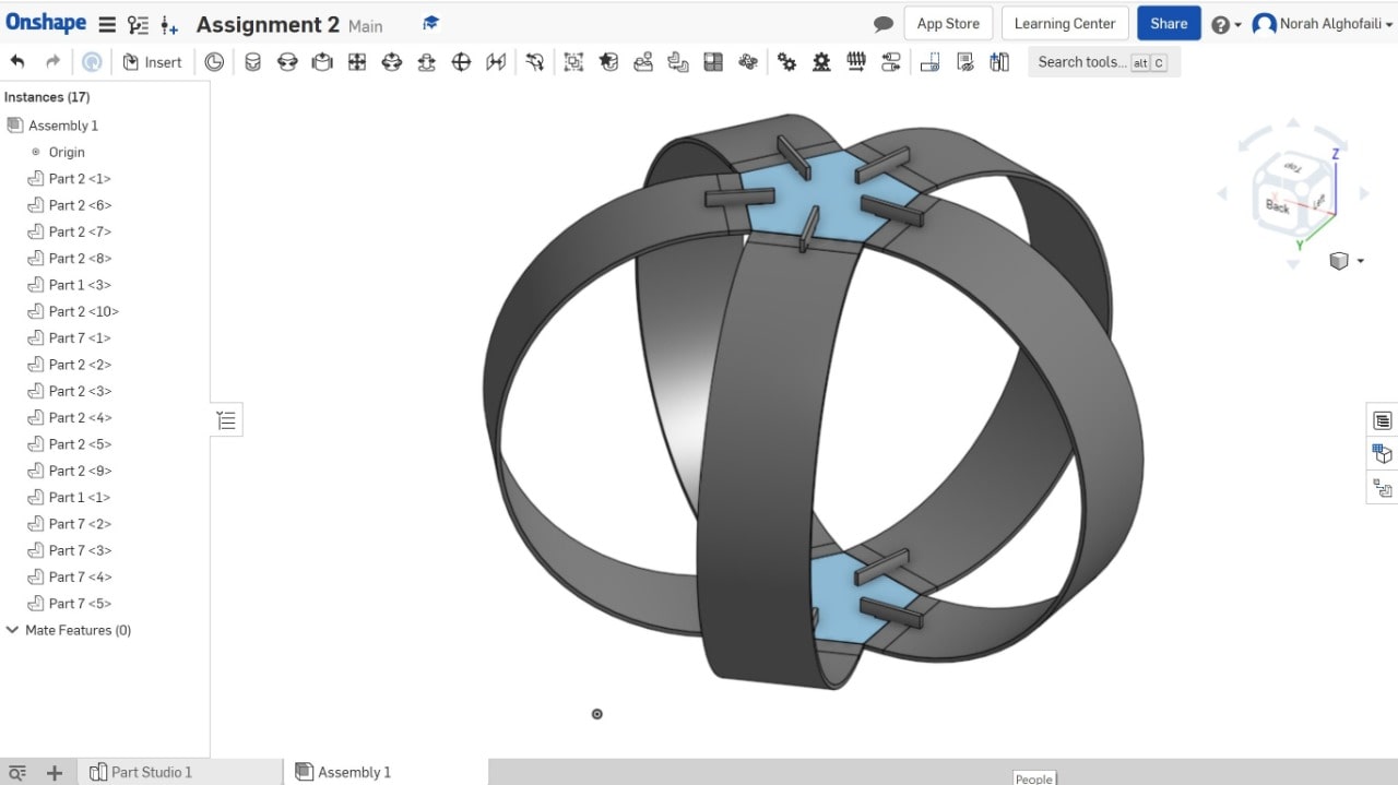
After that, use fastened feature to assemble all the parts together.
The final result.