WOW ELECTRONICS !! A NEW CHALLENGE !!
This week, I had a mix of worry and excitement, and this is because I do not have a good background in electronics. This is my first time of making a PCB circuit. After Prof. Nail’s session, we had a workshop with our instructor, Mr. Yousef Alsinwar, to learn more about PCB, components, soldering and milling machines, in order to make our own PCB circuit board.
This assignment has two parts :
Group Assignment :
In the group assignment, we have to characterize the design rules for our PCB production process.To check the group assignment click on this link : Group Assignment.
Individual Assignment :
In this assignment, we were asked to make an in-circuit programmer by milling and stuffing the PCB, and testing it. I have checked the tutorial to get more information and references on how to make the PCB board. This circuit will be used as a programmer for our microcontroller boards that will be done in the next few weeks.
Let’s make it !
How do you fabricate PCB circuits?
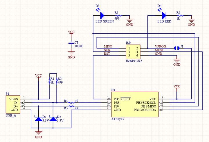
There are many methods of building PCB circuits.I am going to use the Carvey milling machine to make the circuit in a subtractive manner. I will use PCB copper boards and the machine will make the milling/drilling/cutting based on the design that meets my requirements. The circuit that I am going to use is called FabTinyISP, which was created by FAB Academy team and mentioned in the main tutorial.
The circuit has the following components:
To mill the PCB circuit board, just follow these simple steps:
PCB Fabrication:
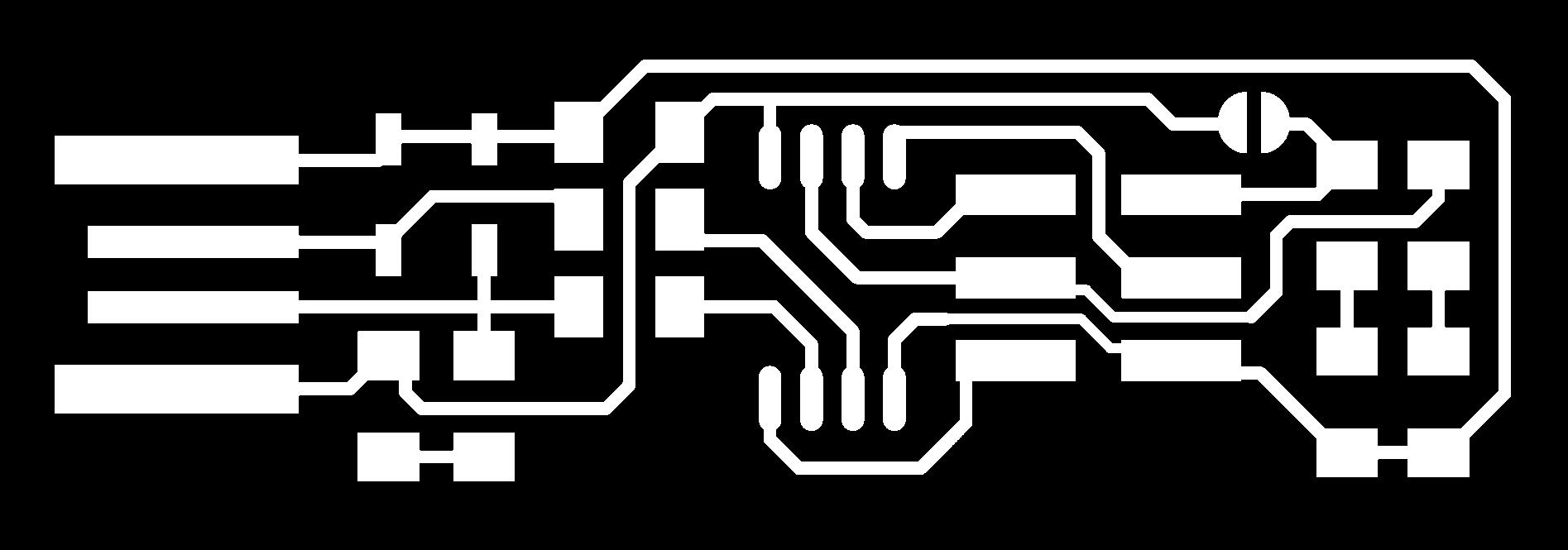
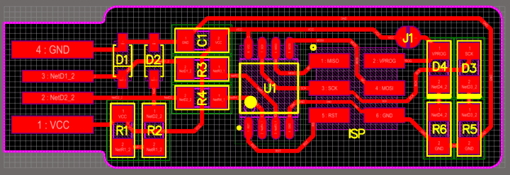
1. Download the traced circuit drawing outline cutout from the tutorial.
Trace :
Outline Cutout :

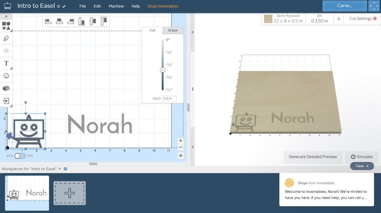
2. Use an online platform called inventables, The software is web-based, and it is called Easel. This tool can control the Carvey machine and run different jobs through it (I created a new account to access Easel tool).

3. Open the platform that runs the carvey machine, which as I have mentioned earlier is called ‘Easel’
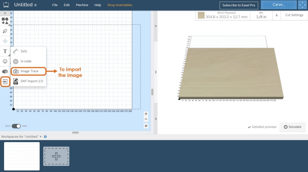
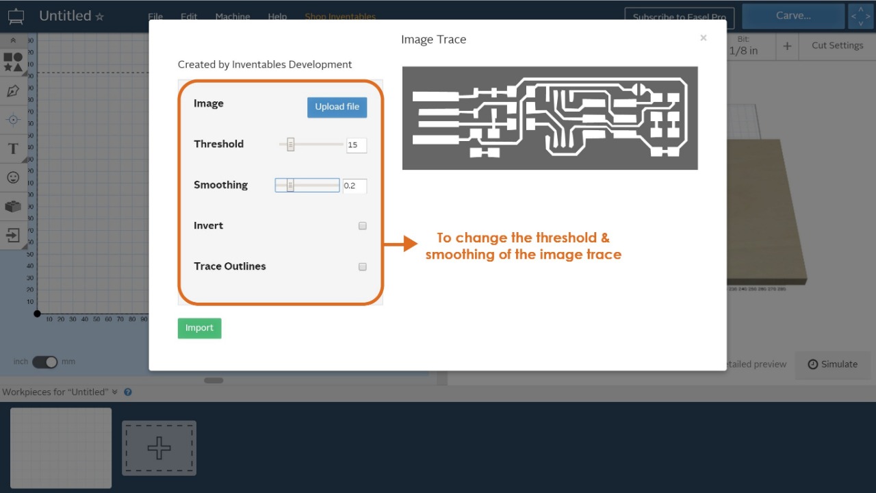
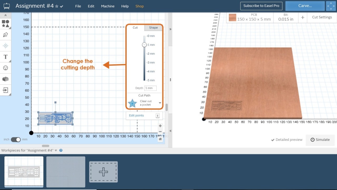
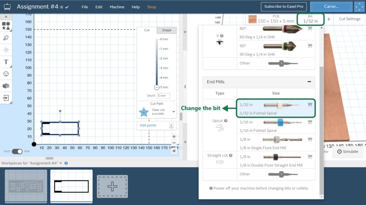
Below is the interface of Easel platform. Let’s explore the features:
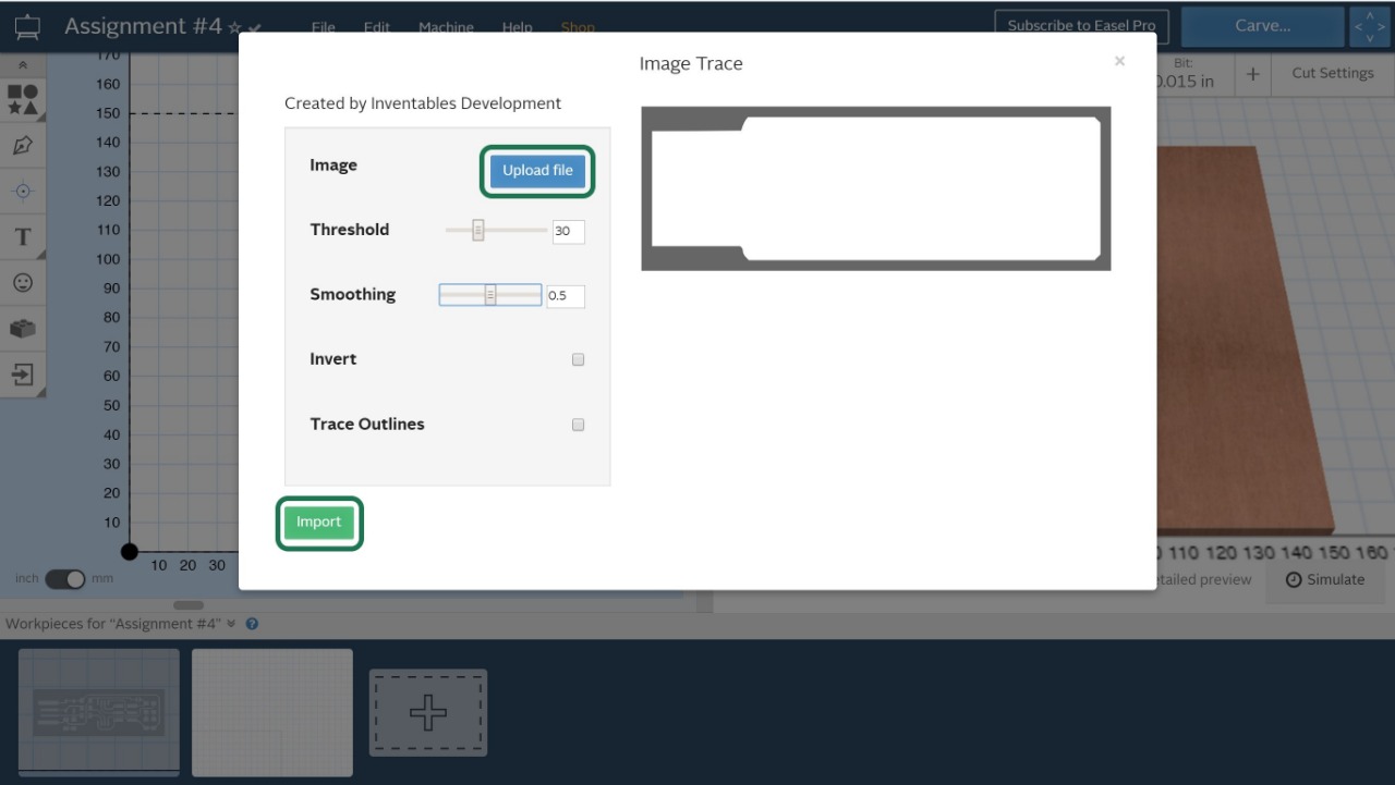
4. Import the circuit drawing by clicking on ‘import’ and then ‘image trace’ (png format). Here it’s important to make sure that the dimensions are correct, and no changes were made after importing the circuit.
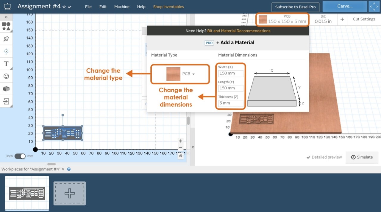
5. Determine the material settings, by selecting PCB, the material dimensions and thickness.
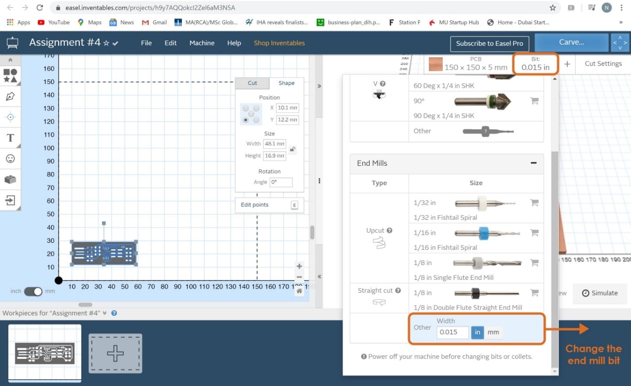
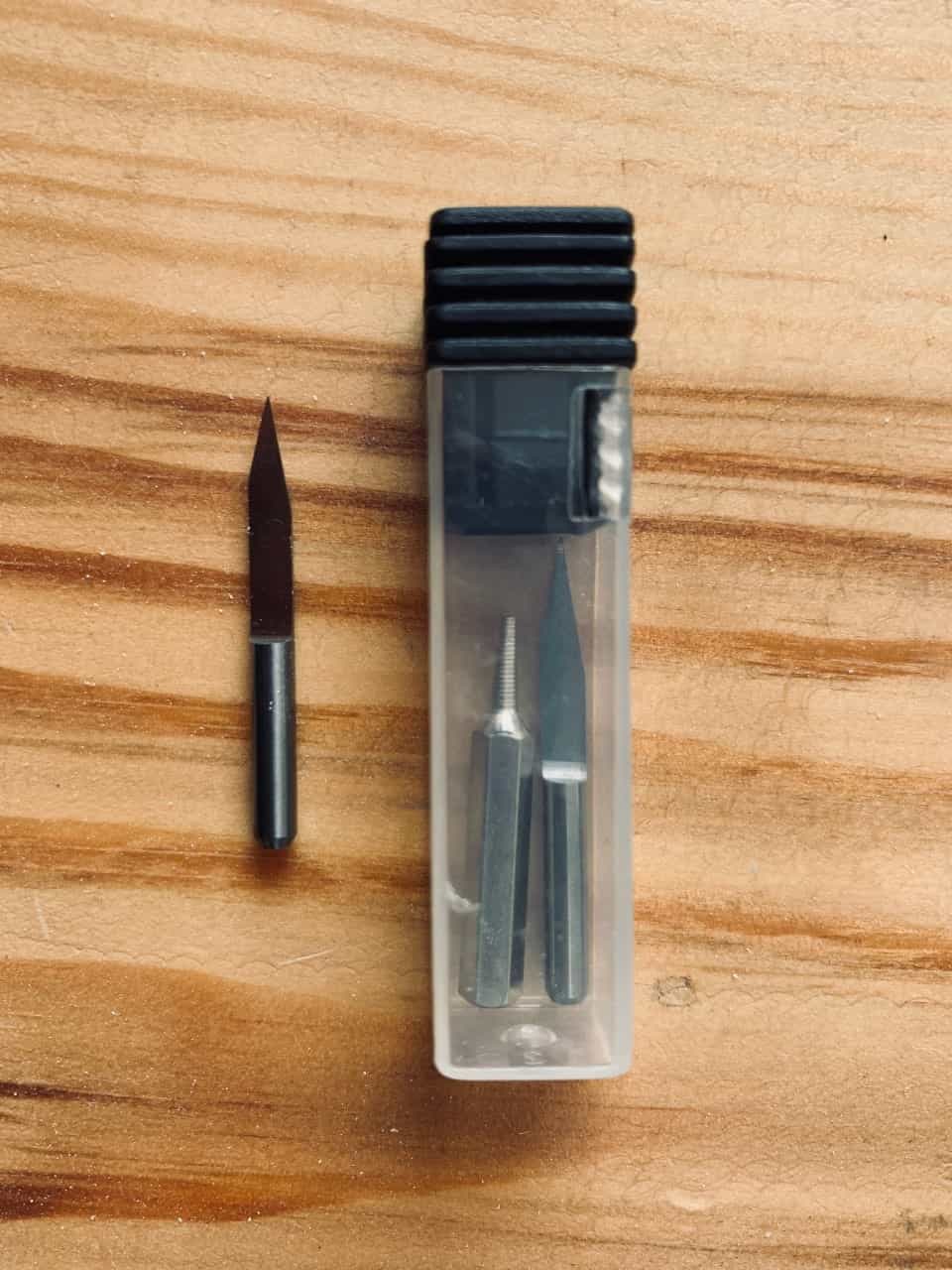
6. Determine the bit settings, by reading the bit data sheet or measuring the bit diameter (for milling 1/64 inch, for drilling and cutting 1/32 inch).
7. Determine the Feed rate, the plunge rate and depth per pass, I read about this topic and I found that the feed rate = 180 mm/min and plunge rate = 90 mm/min.
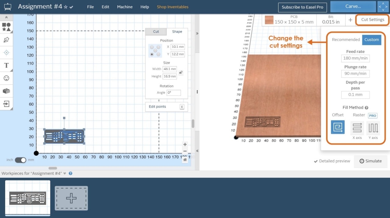
8. Determine the cutting depth = 1 mm.
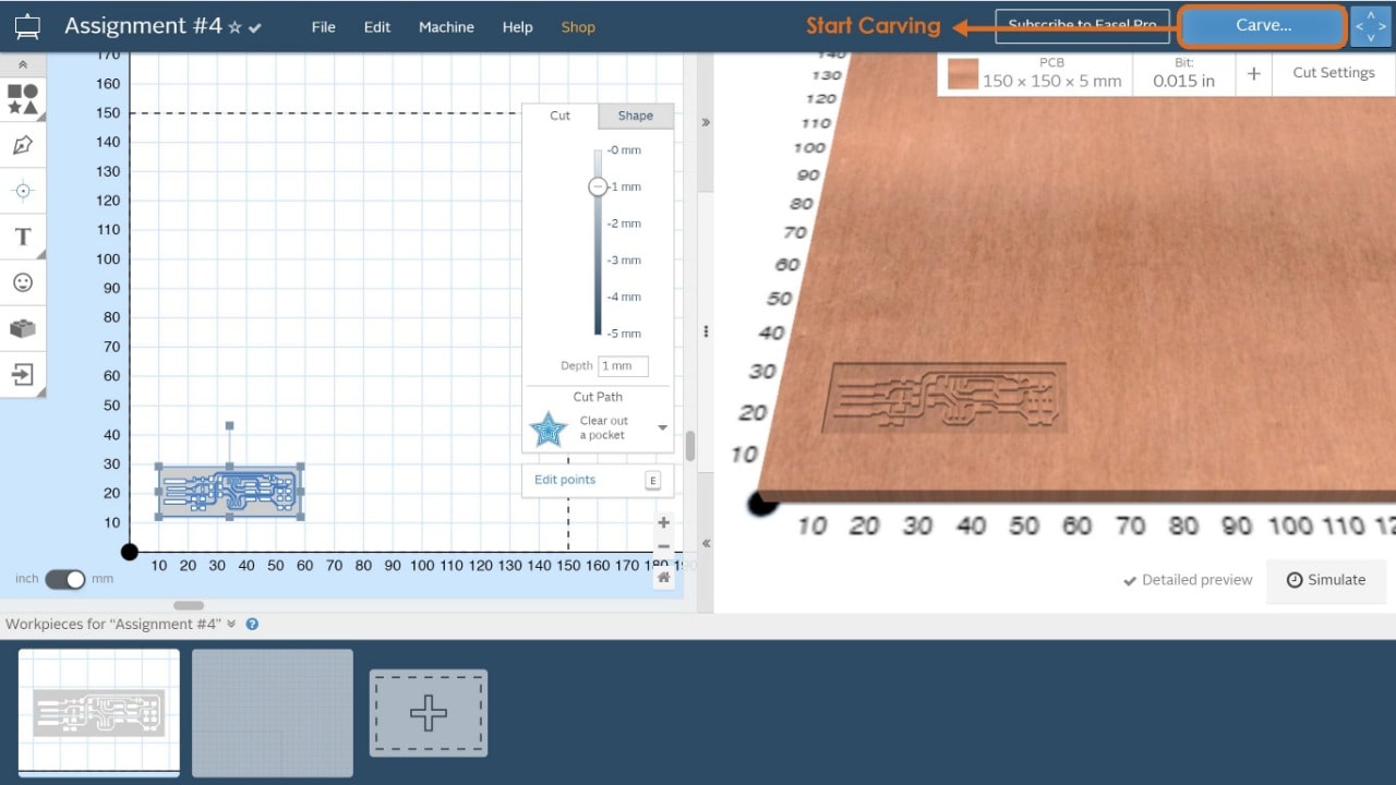
9. Start carving the PCB.
Cutting the outline:
10. Import the outline shape and make sure it’s on the same axis (X,Y) and dimensions.
11. Determine the cutting depth = 5 mm ( The same depth of the material ).
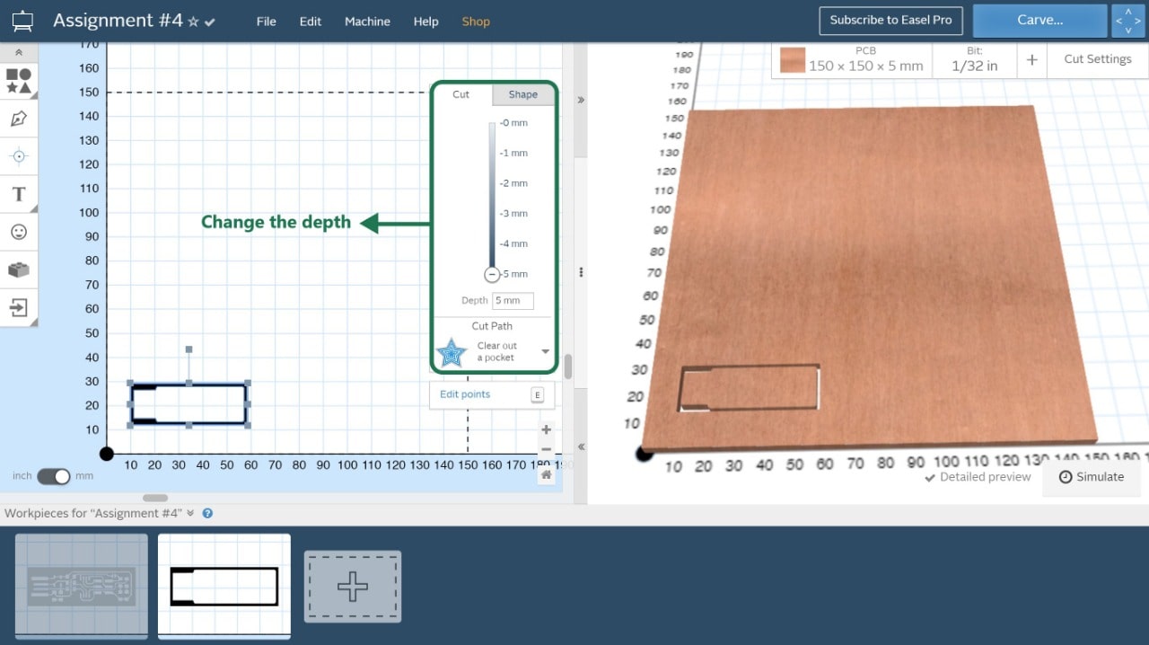
12. Determine the bit settings for drilling and cutting 1/32 inch.
Then Start Carving !
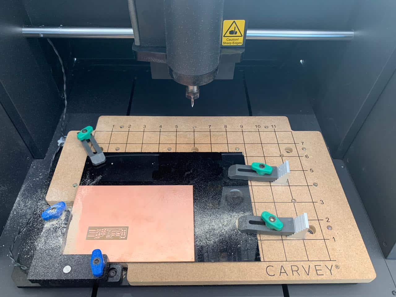
How do you run the carvey milling machine ?
After doing the setting in Easel software, I used the carvey milling machine to cut the board.
We can use variety of materials such as:
Specification :

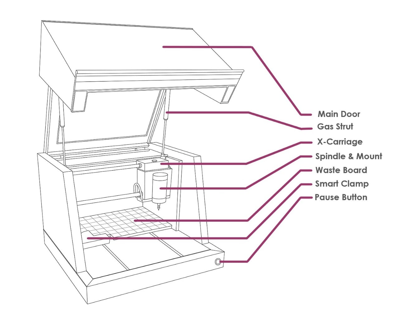
Carvey milling machine parts:
Now let’s mill !
1. Use the 1/64 inch bit to start milling the PCB.
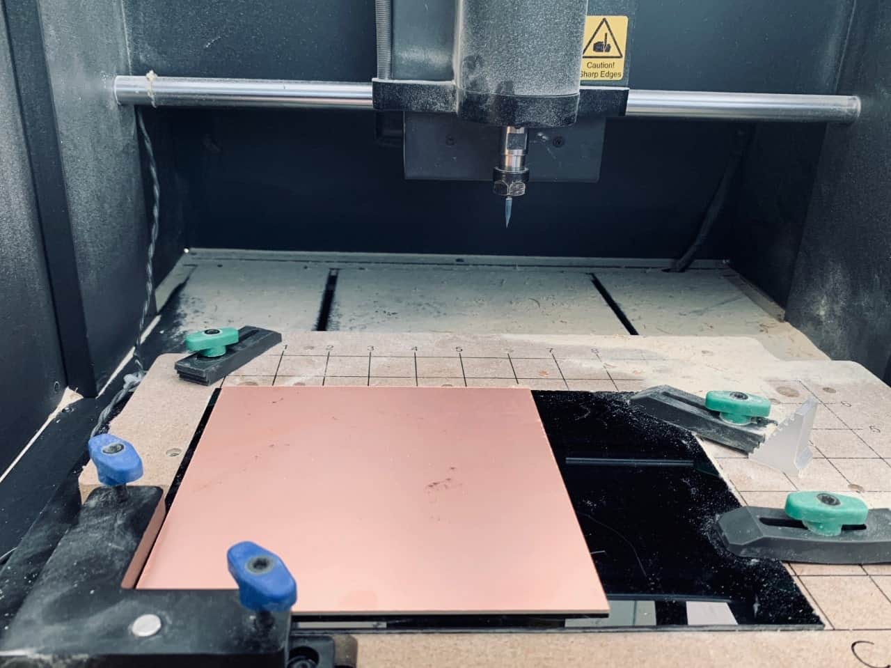
2. Put the material on the board of the carvey machine and use the clamps to make the material stable.
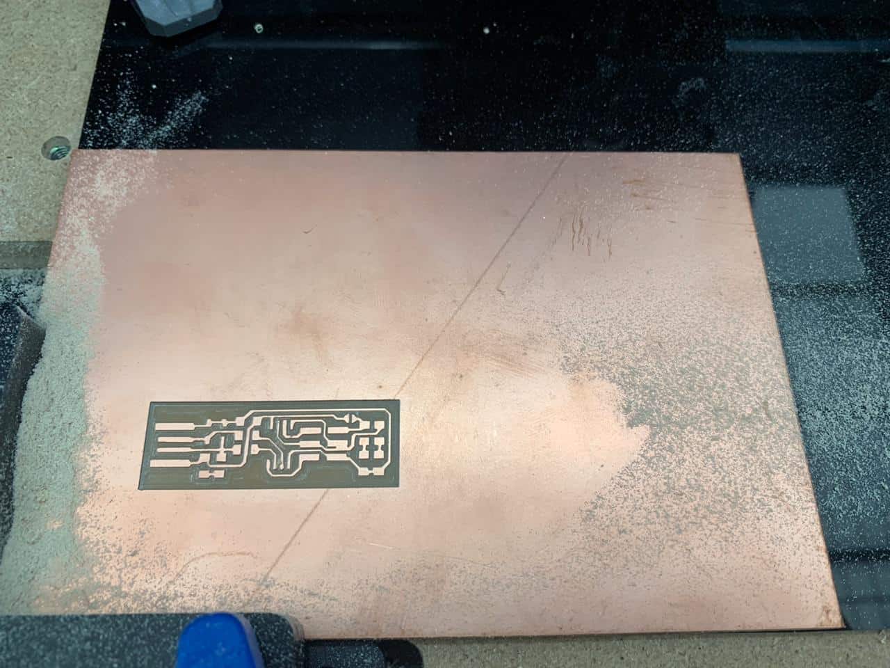
3. After milling the PCB, change the bit to 1/32 inch bit in order to start cutting.
This is A M A Z I N G !
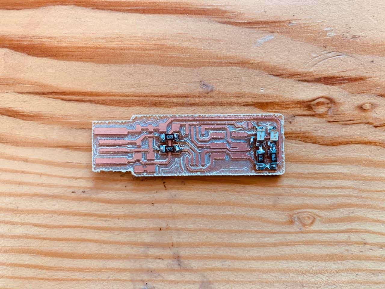
Assembling the PCB
Soldering !
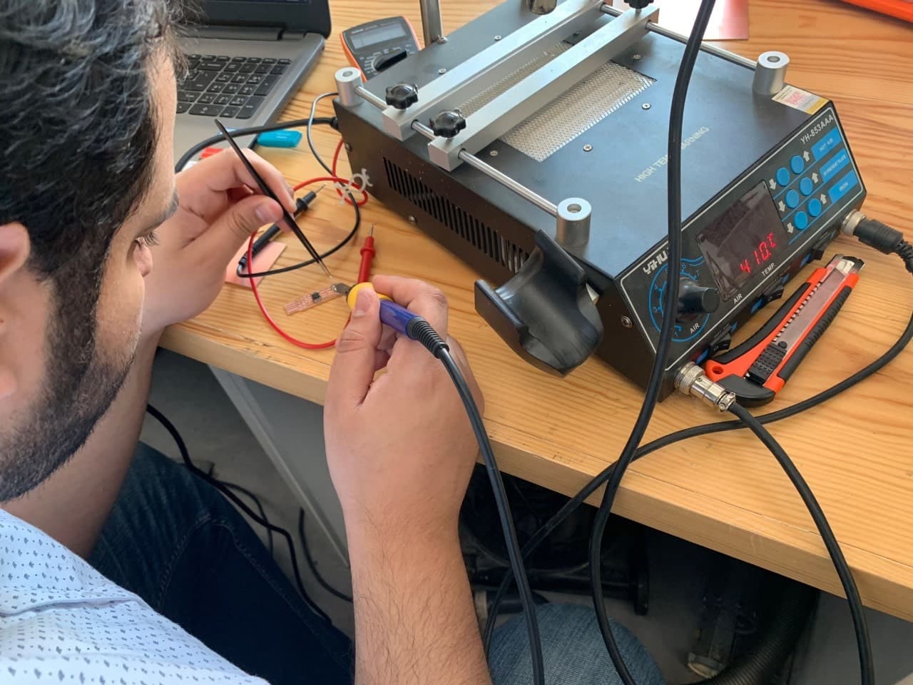
After cutting the PCB board, I started collecting the components and soldering my PCB. This was my first time of soldering. Learning how to solder these tiny components together was a great experience.
The components :
I used this photo as a guide to know the various components:
I faced some problems while I was soldering the components. One of the problems was the components kept moving while I was soldering (maybe because my hands were shaking a little bit).
I used soldering iron and solder wire with tweezer to complete the soldering process. It took hours to get to know the right technique, but I did it :).

It took hours to get to know the right technique, but I did it wahooooo :)
Let’s program it and test it !
I followed the tutorials below as use Windows operating system :
So, basically all I did was to download the following:

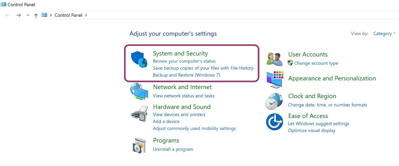
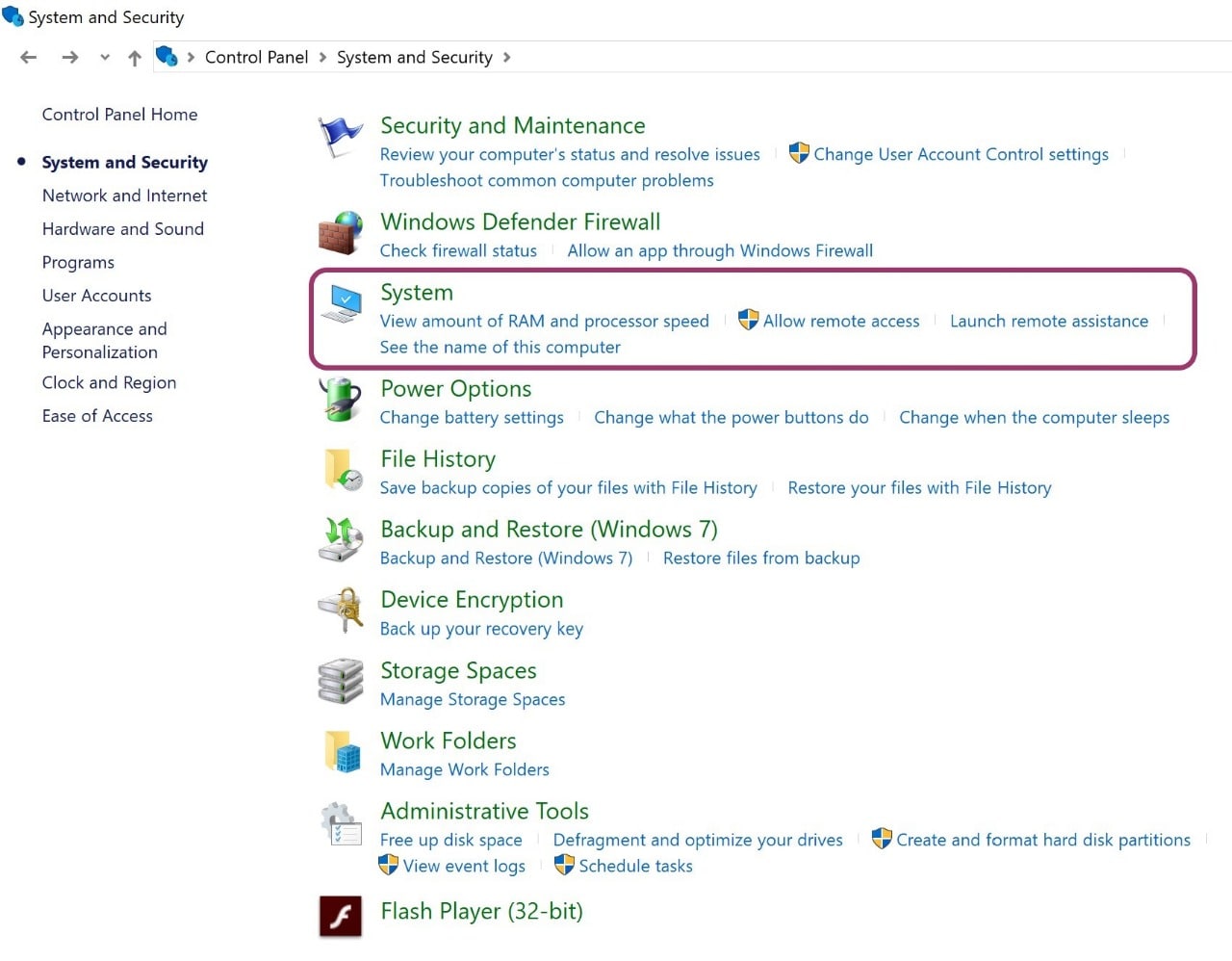
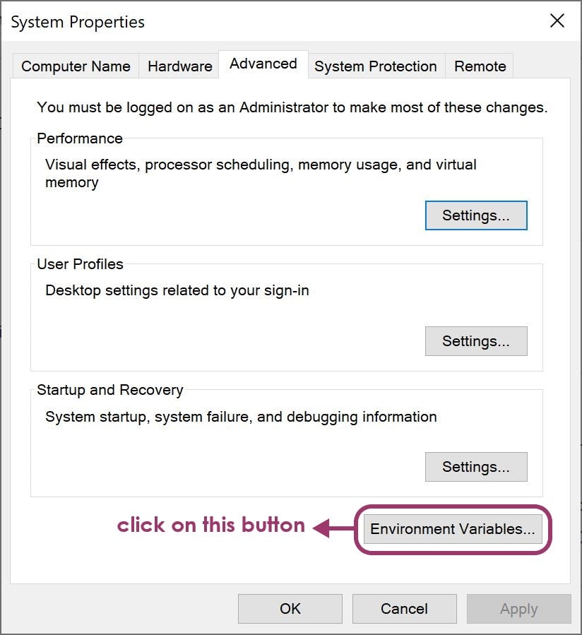
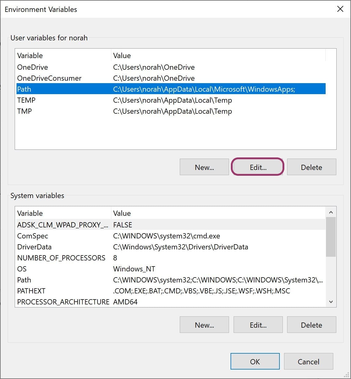
Then I updated the path by going to Control Panel, and then to System, and lastly to Advanced system settings.

I clicked on Environment Variables
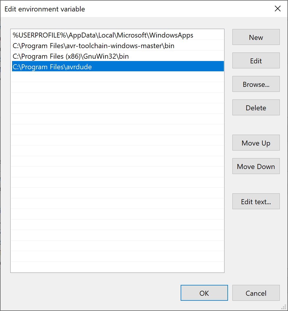
I selected Path and clicked on Edit, to start editing/adding folders location
I added the path where I saved the above mentioned tools that I downloaded to be as the following
Then I downloaded Firmware to start using the command lines. After that, I plugged Arduino and uploaded the sketch called Arduino ISP (you can find it in; File > Examples
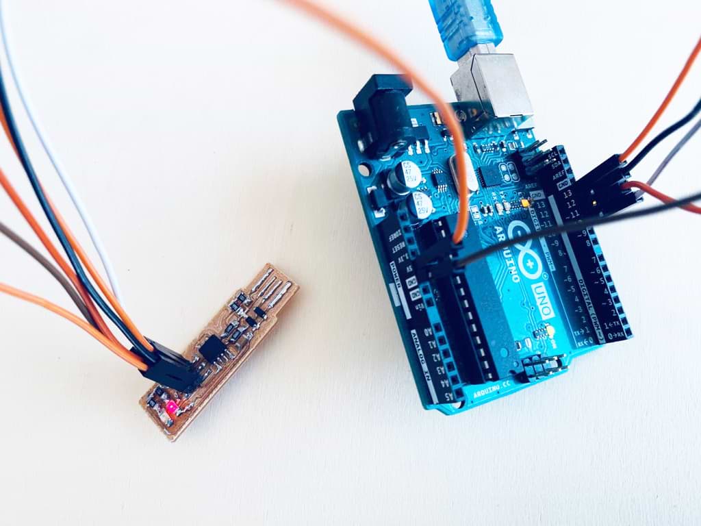
After uploading the sketch successfully, I needed to wire my board and connect it to the Arduino. I had 6 main wires to be connected as the following:
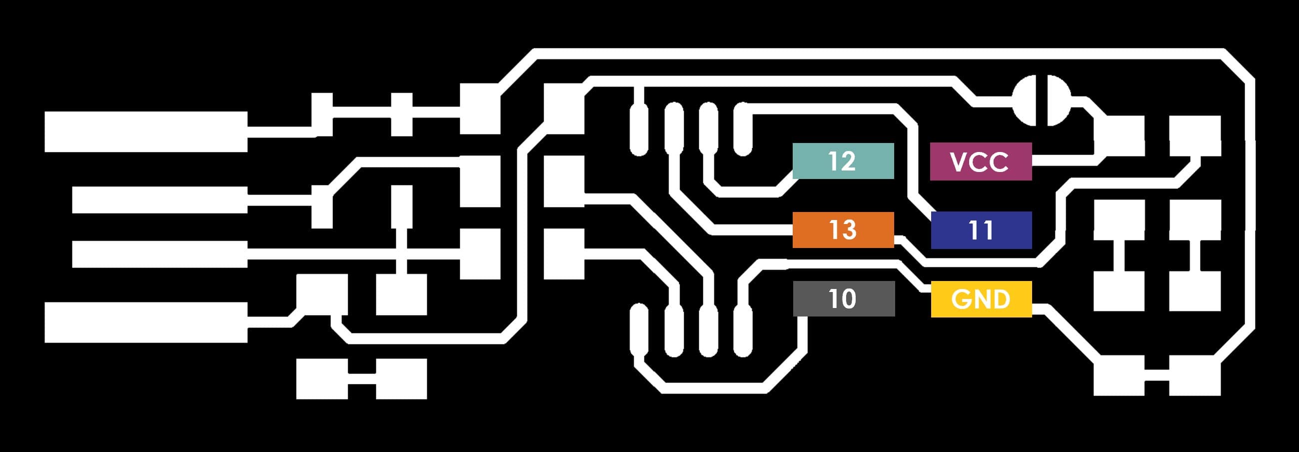
The above mentioned pins in blue color refer to Arduino pins.
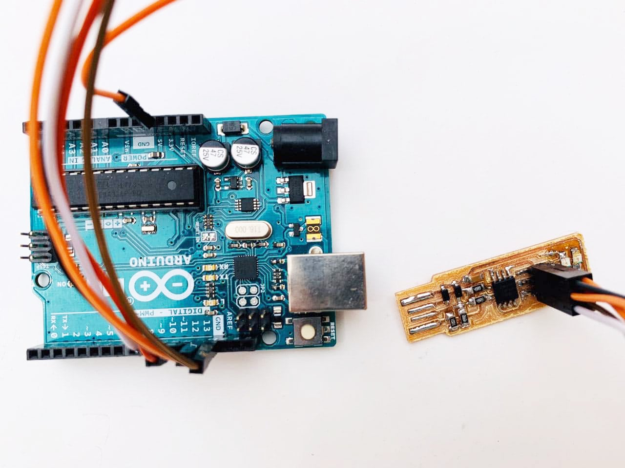
Now the wires have connected!!
It’s important to change the port in the firmware file according to the real port that appears when Arduino is connected.
You can find make file inside firmware folder, edit Make file > Edit with Notepad++ > replace COM10 to COM4 (or any COM based on what shown in the Arduino IDE software).
Now, let’s start with the command lines which will help to activate the board function:

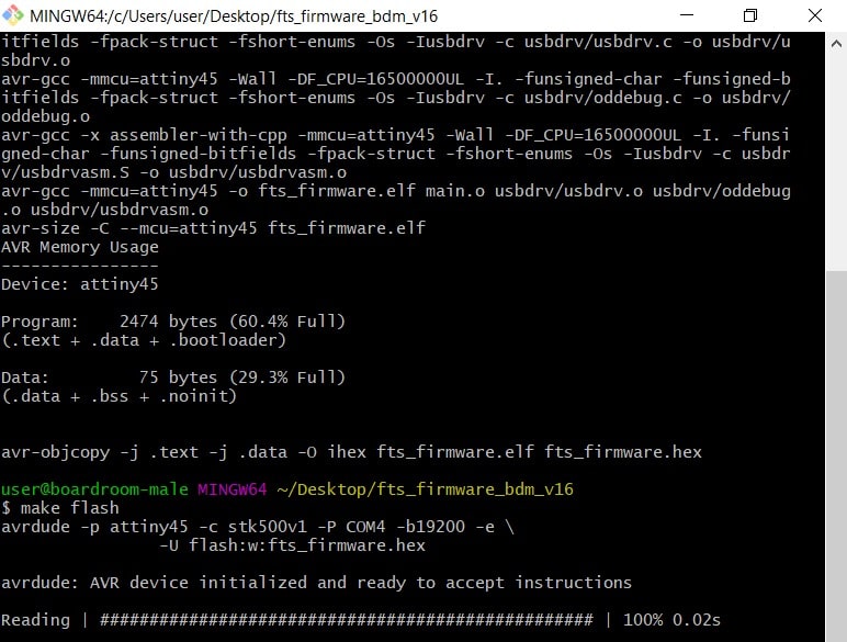
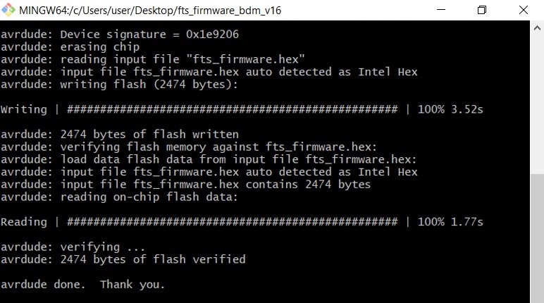
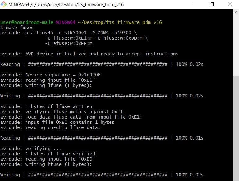
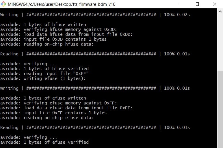
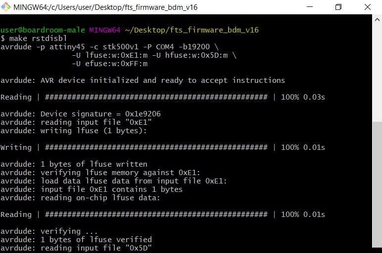
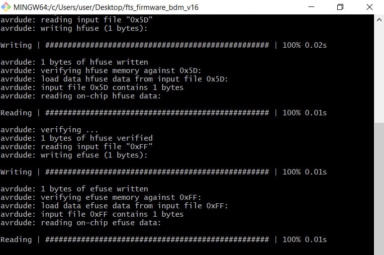
I connected the ISP and arduino to the USB port and it is lighting up.
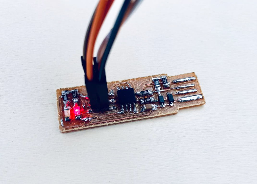
Now ! Let's connect the ISP to USB hub USB hub in order to make sure that it's working.
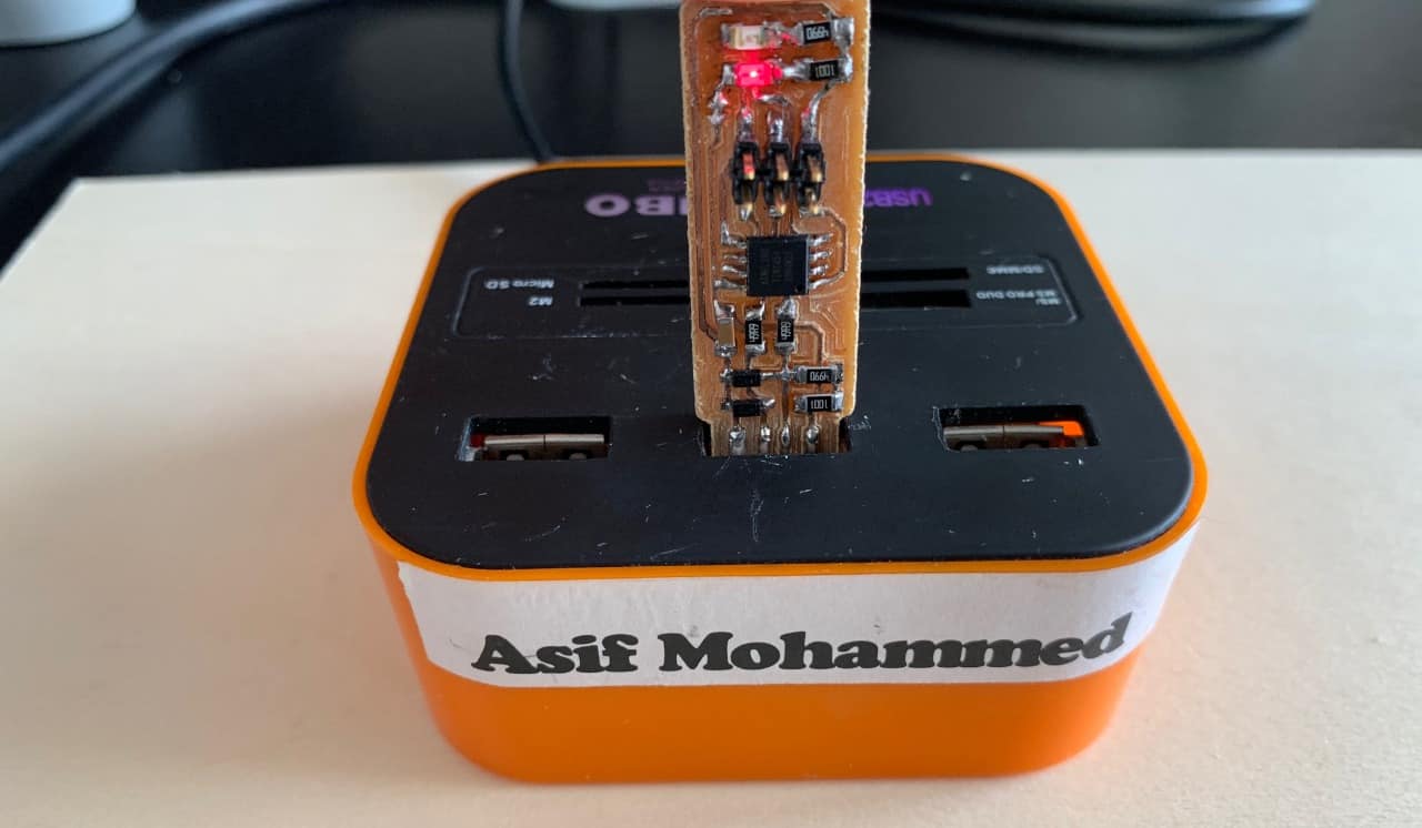
D O N E .. D O N E .. D O N E .. I LOVE IT !