Mechanical Design & Machine Design
Group assignment
For the group documentation, please check group assignment page here: Mechanical & Machine Design (Group page)
Mechanical Design
For these 2 weeks’ challenge, Tiago and I thought of what we could make with what we had at hand, working at a distance and still without fablab access due to Covid19 lockdown. Nevertheless, I had access to my soon to be Fab-Lab, so I worked there.
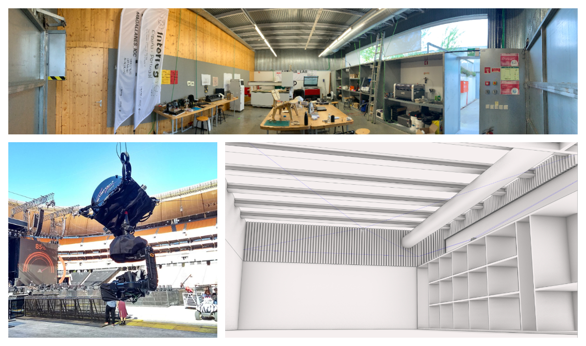
Inspired by Jany Ylioja’s efforts on the remote fablab, I thought that a remote controlled camera in the lab would be useful to monitor each of the machines as they’re being used.
In our weekly remote class with Fab Guru Luís Carvão, we discussed making a robotic arm on a track to monitor the machines at _ARTERIA_LAB, where I work. We thought about controlling it with an esp32-cam, considering options such as CoreXY as a motion system for the arm that would have the camera at the tip.
Finally we decided on a spider cam, like in football stadiums, as it should be able to move in the entire makerspace and focus on any of the machines in the room, and be feasible in the time and location constraints.
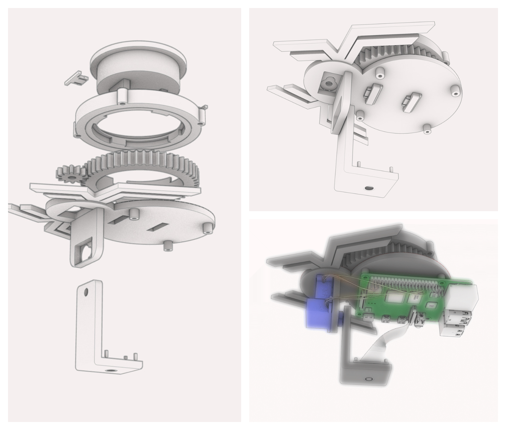
The system is composed of a hanging platform with a Raspberry Pi and Pi camera, as that is what Tiago Fernandes and I had at hand. That Pi controls two servo motors for yaw and pitch, and sends commands to a base station that spools the wire with 4 stepper motors. These are controlled by a CNC Shield on an Arduino Uno, which receives commands from the Raspberry Pi over wifi, through an ESP8266 breakout board. We both had these components and projected the system based on what we had.
I offered to work on the mechanical side of the Spider Cam. I designed the motion system, over several iterations, and also redesigned Tiago’s hanging base, but mainly for aesthetic reasons.
For the first prototype, I planned to use 4 stepper motors to spool nylon wire, hung from the four corners of the space where _ARTERIA_LAB is.
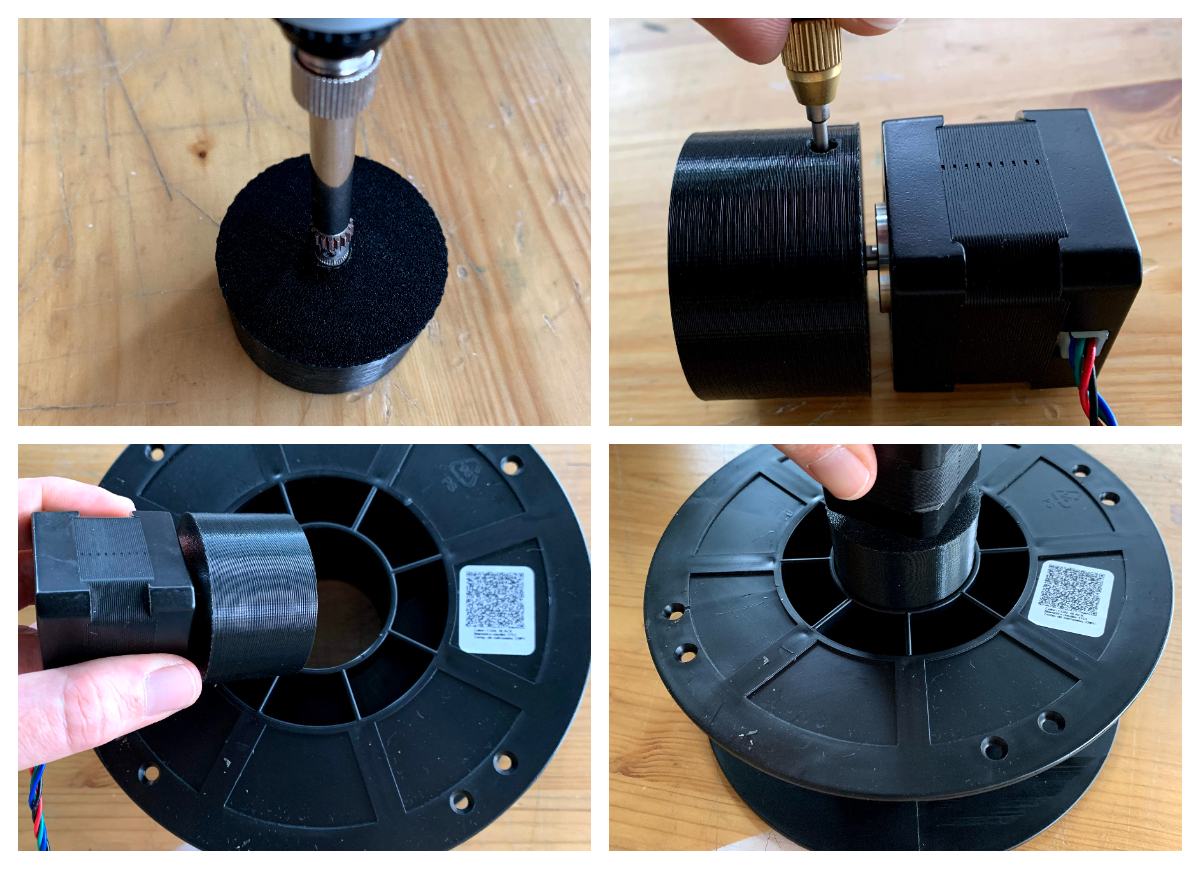
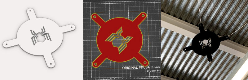
For the first version, I aimed to use parts I had laying around, like 3d printer filament spools and a spool holder. I designed and 3d printed a simple stepper-to-spool adapter, where I inserted a metal gear into the print with the help of a soldering iron.
 |
|---|
| Stepper to spool adapter |
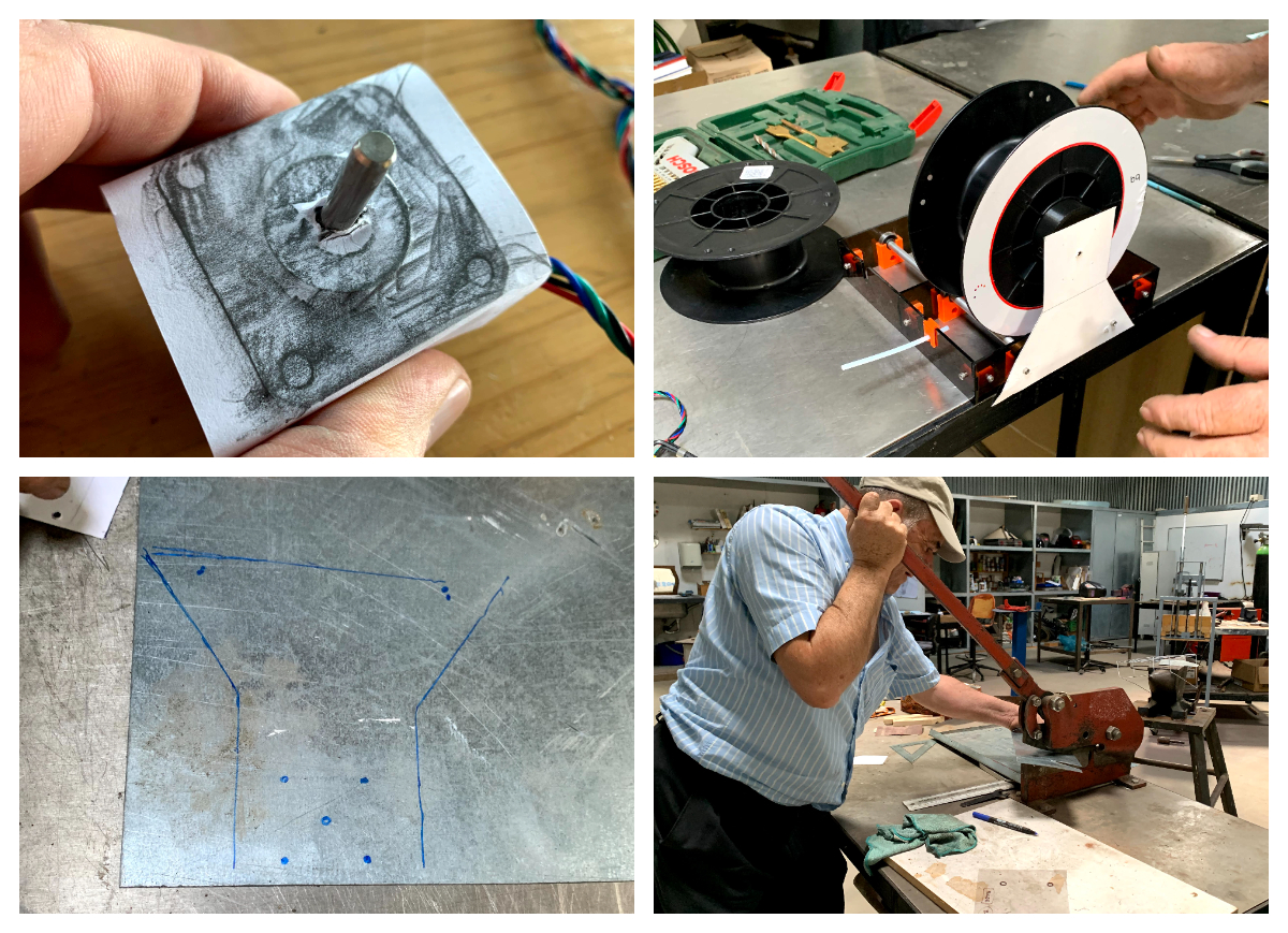
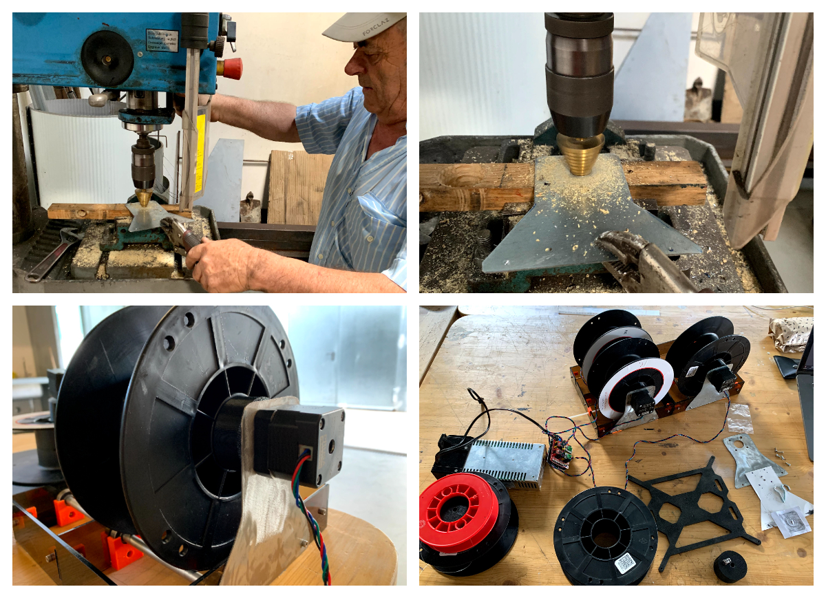
With some Cardboard Aided Design (CAD) and the help of Sr. Francisco, a university colleague and friend, we made metal brackets to connect the stepper motor to the spool holder I had.
 |
|---|
| CAD to the rescue |
 |
|---|
| CAD to the rescue |
I designed and printed a makeshift platform, just to test out the mechanics of the rig.
 |
|---|
| spider platform |
I ran nylon kite wire from the spools to the spider platform, through hooks I attached to the walls at the corners of the Lab, and tested moving the spools manually.
I came to a few conclusions from this test:
-
Moving individual spools would pull or release the platform in each respective direction.
-
There wasn’t enough friction to keep the platform in an elevated position, as even its lightweight weight would pull it down. That meant the motors would have to stay powered to exert holding torque.
-
The rig was very noisy. You can’t hear it because I removed the audio from the video for space saving, but turning the spools rattled a lot, which was amplified by the metal structure it sits on top of. The spools were only held in place by the metal bracket on one side, which was too thin to hold them up. The plastic spool rolled on rods held by axial bearings, but this still resulted in undesired vibration, probably from the unevenness of the spools and general elasticity of the construction.
-
Nylon kite wire is actually quite flexible, and elastic, stretching and contracting with tension, which introduced extra wobble, something I’d like to control better.
These findings were confirmed to a greater extent when we tested driving the rig with the stepper motors.
I hooked up the stepper motors to the CNC Shield and to a spare 3d printer power-supply, and started programming ramp up and ramp down code with much needed help from local Fab Guru Luís Carvão. At first there was lots of debugging to do, measuring current from the Allegro drivers to the motors, configuring steps per millimeter in the code, determining appropriate speed, and starting to figure out a way to write speed ramping functions, which is a real challenge for me, as I’m not very programming inclined. Still, we managed to get some movement on one axis, and the motor was moving normally, i.e. without too much racket. But the rig was still quite noisy.
So, with code starting to look promising, but my brain in a pulp from a long remote help session and all the noise, it was decided that a new iteration on the motion rig was due.
Machine Design
I set our to design something I could print, that included:
-
Better stability for less racket
-
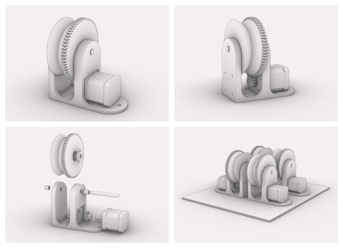
Motor would drive the spool through a gear system rather than directly, for higher torque
-
The spools needed bearings to ride smoothly on the axes
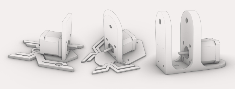
After a few iterations, gradually realizing what was needed for the rig to work, I eventually arrived at the final design.
 |
|---|
| Design iterations |
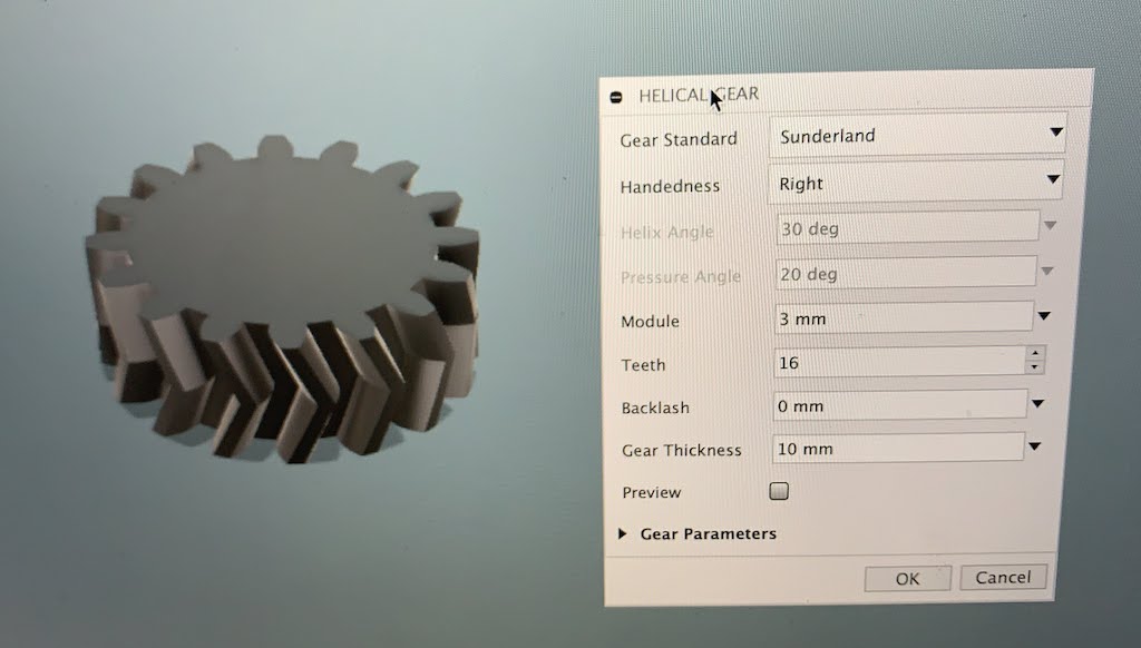
I still like modeling in Rhino, but I resort to Fusion 360 for some parts of my work, like modeling herringbone gears, which I then import to Rhino as STEP files for further design work.
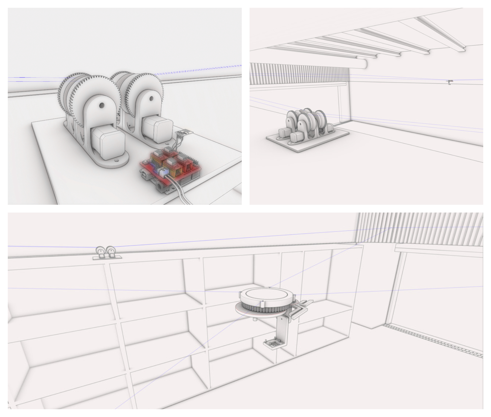
I 3D printed all the parts, assembled each of the spooling mechanisms and screwed them on a scrap wood board, so that the pulling tensions didn’t move them around. The movement was much smoother now!
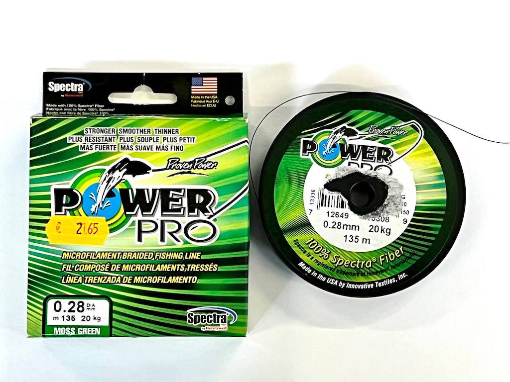
I also swapped the nylon wire for some fishing line, which is a 0.28mm braided wire that is flexible, but not elastic. It’s made so that fishermen can feel the fish tug on the bate and it can hold up to 20Kg, so it’s plenty strong for our purposes.
By this time Tiago had finished his gimbal assembly, so I set out to redesign it slightly and 3D print it, to connect everything and start on the programming of the electronics.
Here, the mockup of the base station can be seen with the CNC-Shield on the Arduino Uno, with the ESP8266 for wifi.
Implementation
To set all this in action, Tiago did all of the programming and I implemented it locally. His documentation describes how to setup the Raspberry Pi, where to connect the servo motors on the GPIO, and also how to connect the CNC-Shield to the ESP8266. We worked remotely on video call a few times and he helped me program the ESP8266 as well.
I connected the Raspberry Pi to a power bank, because that was the way we found to feed it in mid air. THE arduino was powered over usb, as the CNC-Shield doesn’t feed 5v to it, even though it’s supplied by 12V, in our case from a salvaged power brick.
Once we had everything physically connected and programmed, connected to my local wifi, we even established that Tiago had remote access to my network, which allowed him not only to debug the code but also adjust some of it so that it worked better. It was super cool.
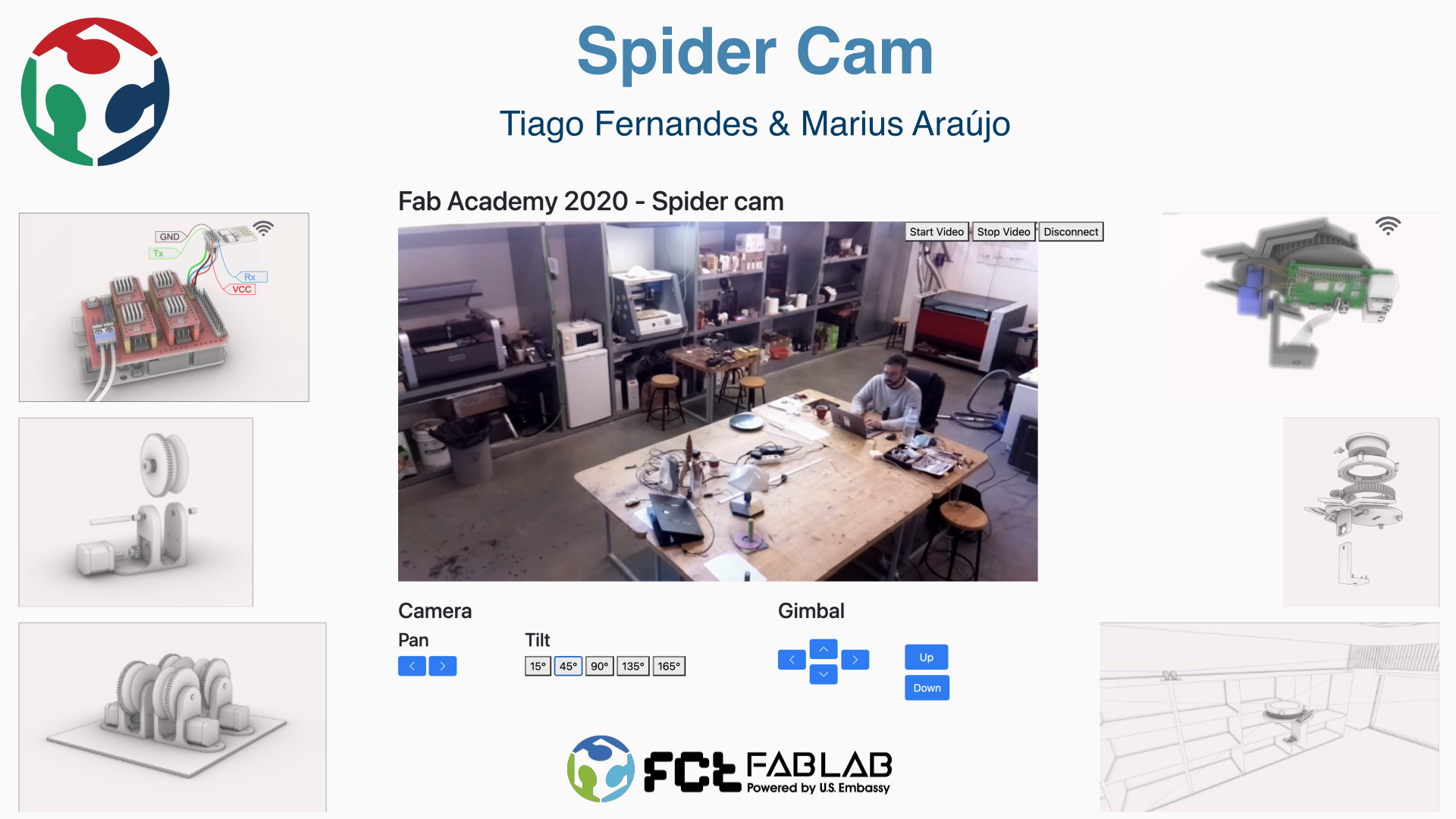
He had programmed an interface website that allows us to rotate and move the gimbal, as well as the camera, and see the video feed.
Here are the Slider and Video we presented with.
Opportunities for improvement
If I were to restart this project, I’d use an ESP32 Cam, because it’s much lighter and efficient, and design a power management system with 18650 batteries, of which I have a few, with usb charging. Instead of the Arduino Uno with CNC Shield, I’d try to use a Urumbu SerialStep controller with wifi.
Files
Checklist
Mechanical Design (part 1 of 2)
Group assignment
- Design a machine that includes mechanism + actuation + automation
- Build the mechanical parts and operate it manually.
- Document the group project
Individual assignment:
- Document your individual contribution.
Machine Design (part 2 of 2)
Group assignment
- Actuate and automate your machine.
-
Document the group project Individual assignment:
-
Document your individual contribution.
Learning outcomes
- Work and communicate effectively in a team and independently
- Design, plan and build a system
- Analyze and solve technical problems
- Recognise opportunities for improvements in the design
Have you?
- Documented the machine building process to the group page
- Documented your individual contribution to this project on your own website
- Linked to the group page from your individual page as well as from group page to your individual pages
On the group page, has your group:
- Shown how your team planned and executed the project
- Described problems and how the team solved them
- Listed future development opportunities for this project
- Included your design files
- Optionally included an approx. 1 min video (1920x1080 HTML5 MP4) + slide (1920x1080 PNG)