3D Scanning and Printing
3D Printing
Fablab FCT has four 3d printers, all of the FFD (fused filament deposition) persuasion. An original Ultimaker and Ultimaker2+, a Creality Ender 3 and a Blocks One. All the printers have roughly the same build volume of 200 cubic millimeters, where the Ender 3 has a slightly taller 23cm build height.
In order to have good results, printers have to be very well calibrated, both mechanically, electronically and in the slicer used to prepare the models for printing. This calibration varies from model to model, whether it is open or close sourced, open sourced ones being usually characterized by also having an open firmware like Marlin or Repetier, which allows for adaptations and particular calibrations. At FCT Fablab, Cura is used with all the printers, which have been setup and configured by our Fab Manager, Filipe Silvestre.
We printed a 3d Print Test on the Ender 3, in PLA, at 0.2mm layer height, 215ºC at the nozzle and 50ºC at the heated bed.
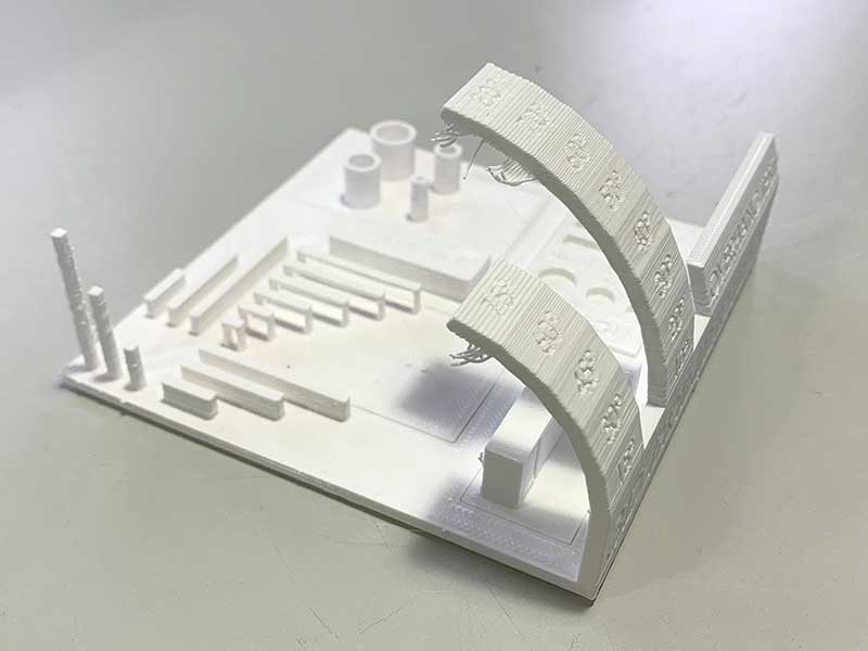
Results show bowing of the base, which is probably due to a flexible heated bed accompanying the normal contraction of the material as it cools at air temperature, as adhesion of the piece to the bed was good. This can be mitigated by fixing the flexible bed element to the hard heated bed at the edges.
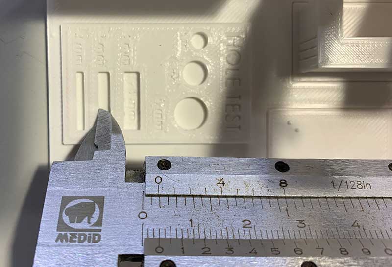
A slight over-extrusion can be observed as on the hole tests, dimensions are smaller than expected, as measured with the vernier calipers. This issue can easily be mitigated or resolved by adjusting the flow variable in the slicer, which controls how much plastic is extruded.
Generally, print quality was passable, with a very slight layer missalignment being observed, but overall geometry turning out good. Overhangs were fine up to 60º, bridges and higher overhangs recovered nicely from the first hanging layers.
Individual assignment
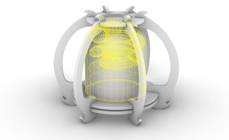
In view of my recent work and this week’s assignment, I decided to 3d print a back enclosure to the speaker frame I assembled last week. The full range driver I’m using lacks bass if used without an enclosure, naturally.

Inspired by sound engineer Peter Kulicki’s youtube video on 3d printing a 3” Subwoofer enclosure, which he released under Creative Commons license on Thingiverse, I ventured into modeling my own enclosure in Rhino, so as to maximize the volume of air my driver is moving for bass extension, in the available space.
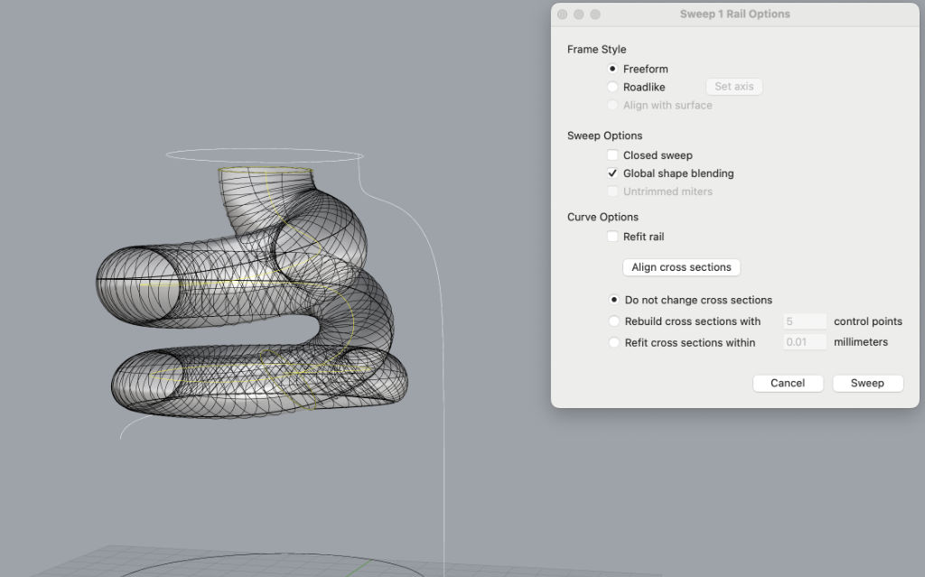
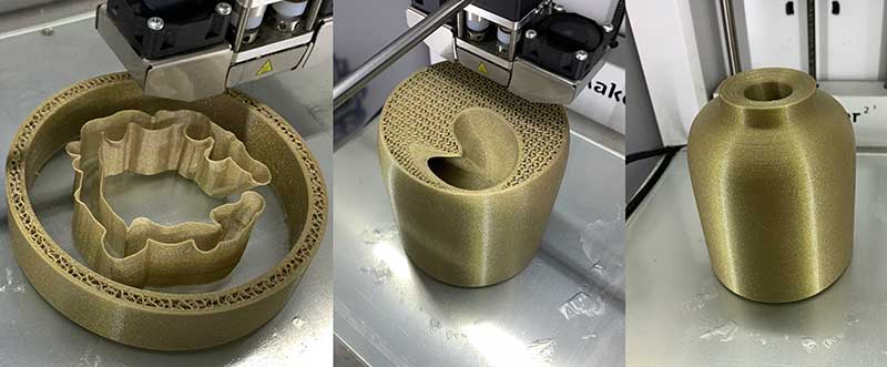
I modeled the exterior in the shape I thought looked alright for the design I had created before, in laser cutting week. The interior shape has a volume to accommodate the driver itself and a spiraled chamber that prolongs the escape route for the air mass moved by the back of the driver, to the top of the enclosure.
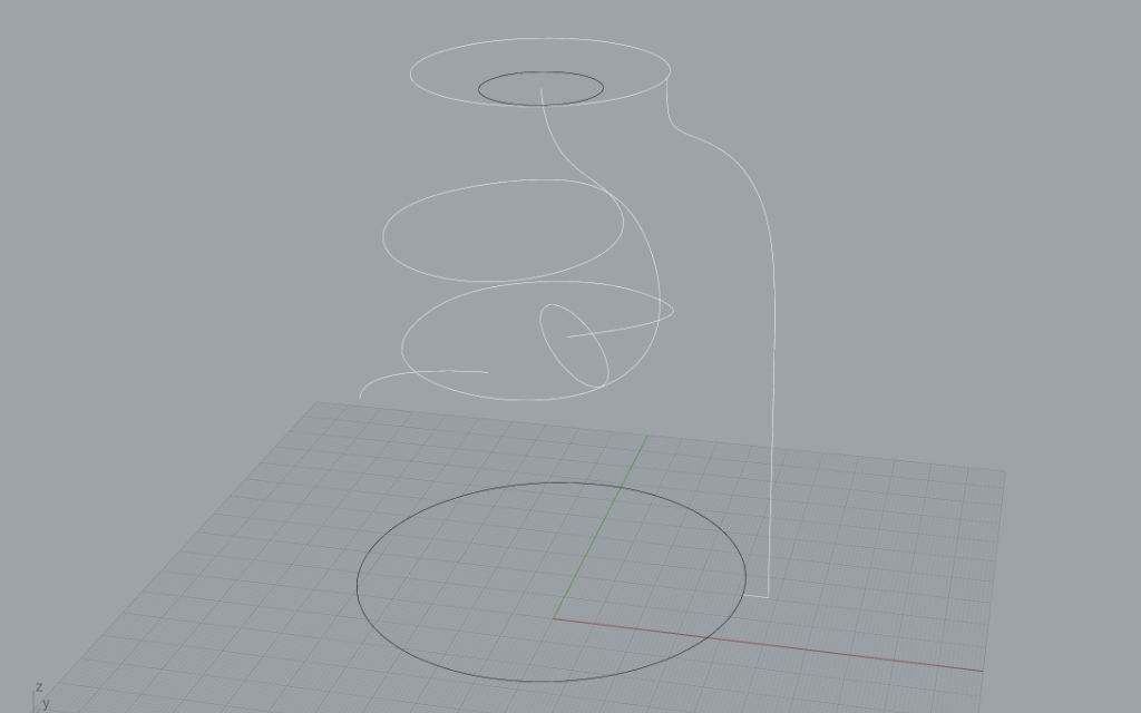
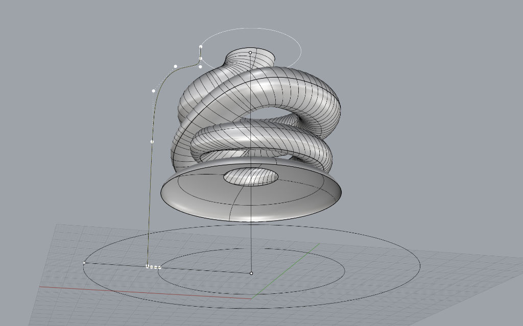
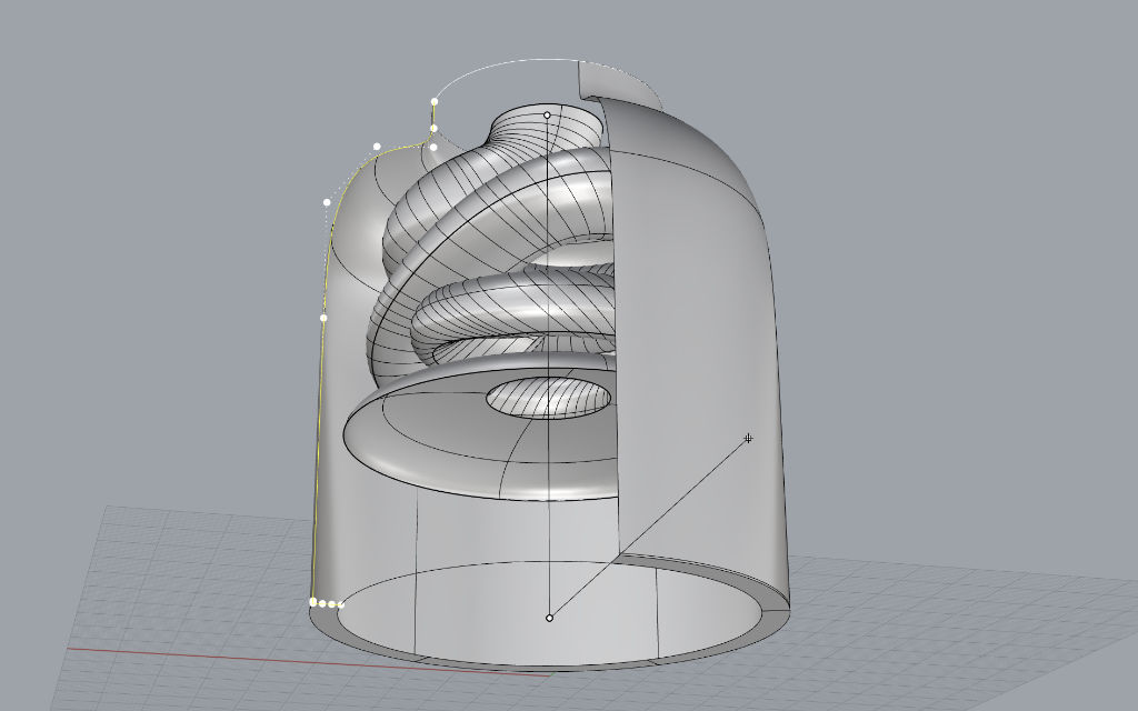
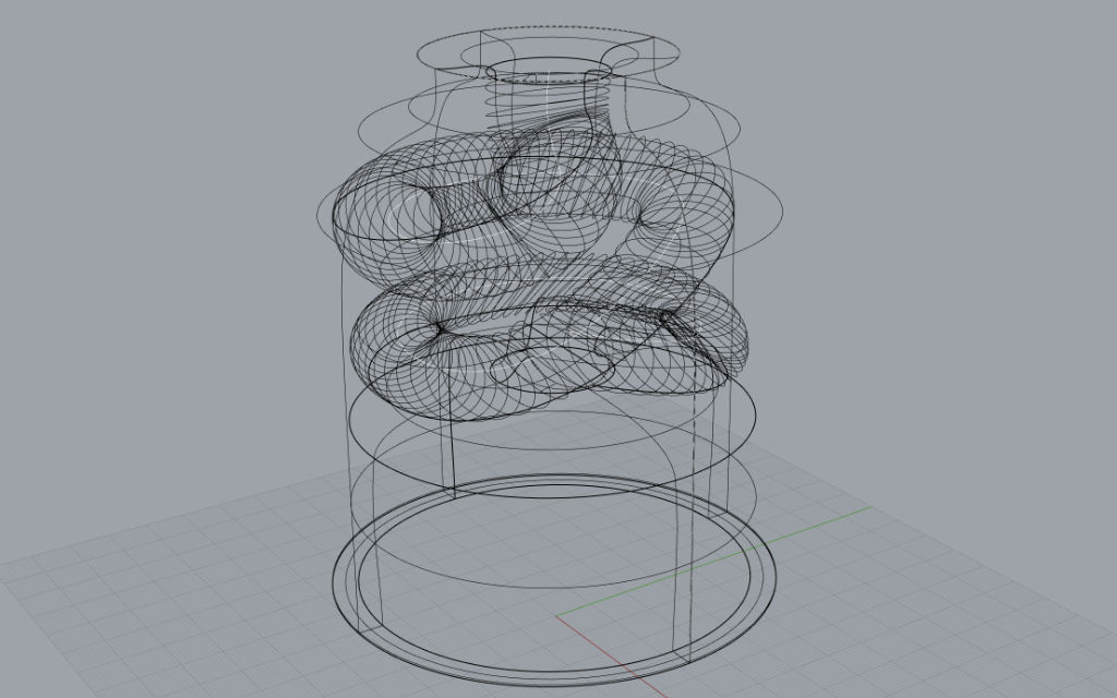
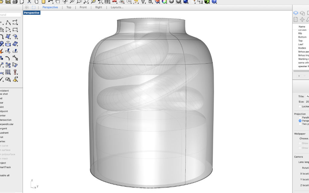
My design is far from perfect, both in the shape of the spiraled exit, as well as in terms of maximizing the available space; nevertheless, in principle it should have a significant effect on the output sound, and it demonstrates a shape that would not be possible to machine subtractively.
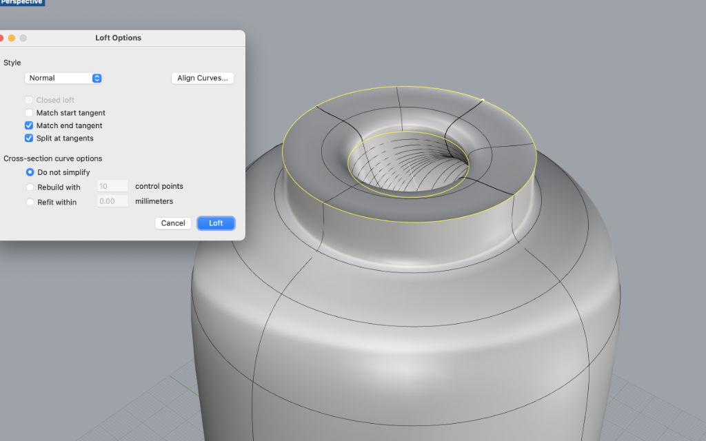
I drew vectors and used lofts, extruded along a curve and other techniques to create the design, and then exported to stl.
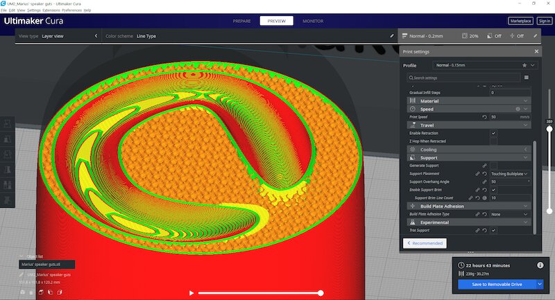
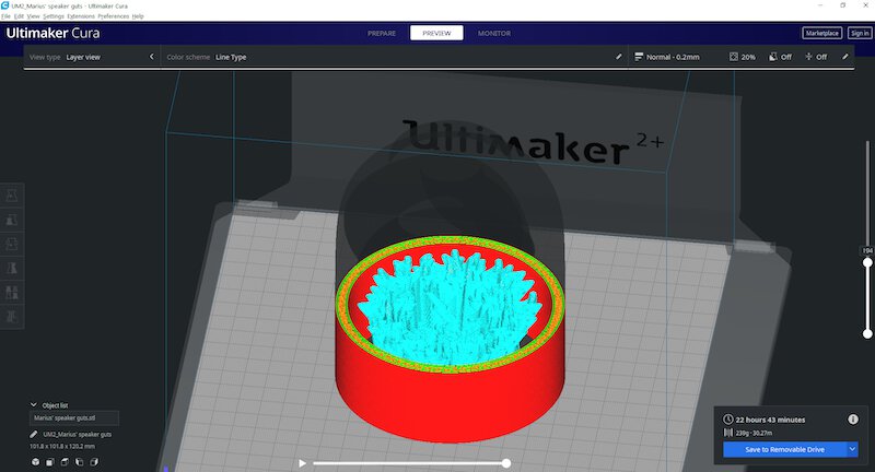
Next, we imported the stl file into Cura and prepared it for printing in the Ultimaker printer, which was working well with PLA. The settings used were:
- 0.2mm layer height - for a fairy smooth vertical aspect
- 4 wall lines - thick walls for better sound carrying characteristics
- 20% infill density - a denser object is better for directing sound rather than absorbing it
- experimental tree support was used to support the interior ceiling of the dome
- 50mm/s print speed - safe print speed on this core xy printer, yielded a 22h23m print, which fit in the allocated time for this project
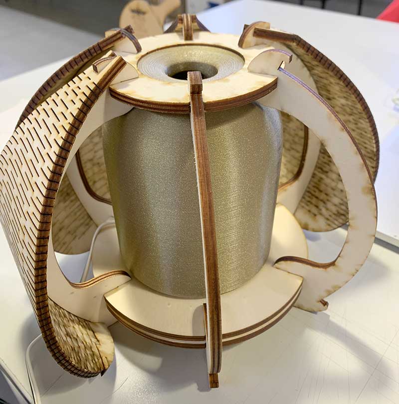
Demonstrating the effect of the enclosure on the audio delivered by the driver.
Conclusions on 3d printing
3D Printers
This week I had the opportunity to try out two 3d Printers: the Ender 3, and the Ultimaker 2+
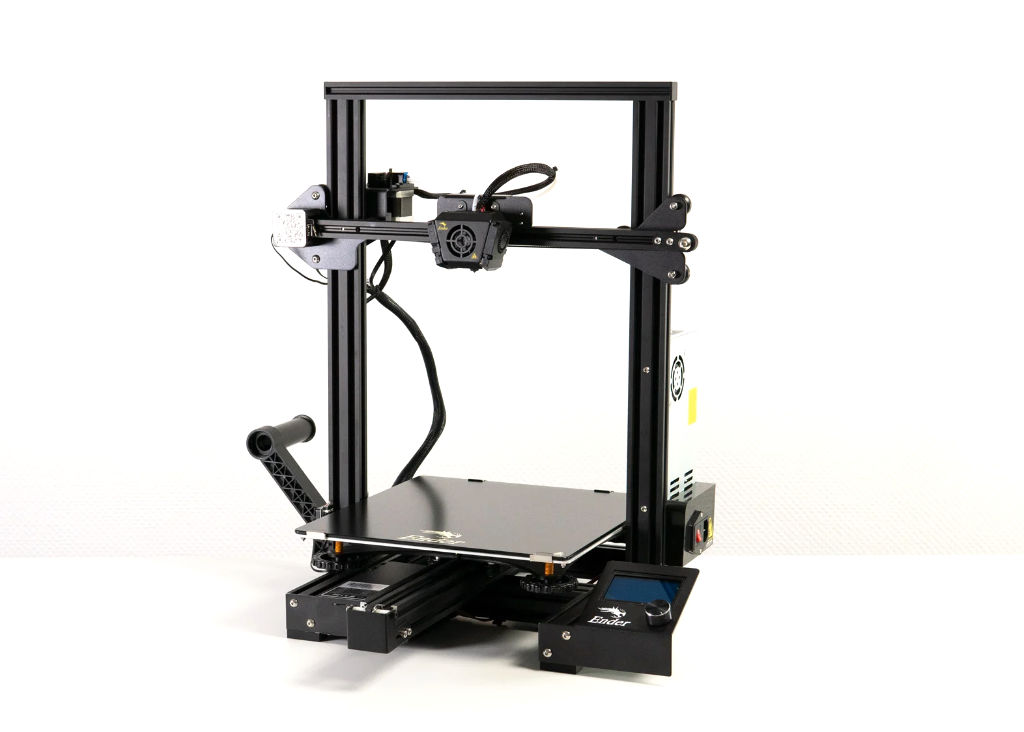
The Ender 3 is a popular desktop 3D printer known for its affordability, relative reliability, and ease of modification. It’s main characteristics are:
- Build Volume: 220mm x 220mm x 250mm.
- Frame: Sturdy aluminium.
- Print Bed: Heated.
- Print Speed: Up to 180mm/s.
- Resolution: Up to 0.1mm.
- Filament Compatibility: PLA, ABS, PETG, TPU, and more.
- User-Friendly: Simple knob-operated control panel.
- Modifiable and Upgradable: Open-source design allows for customization.
- Affordable: Provides reliable performance at a budget-friendly price.
I understand it’s popularity, but I find it takes a lot of tweaking and adjusting to get decent results, so I’m not really a fan.
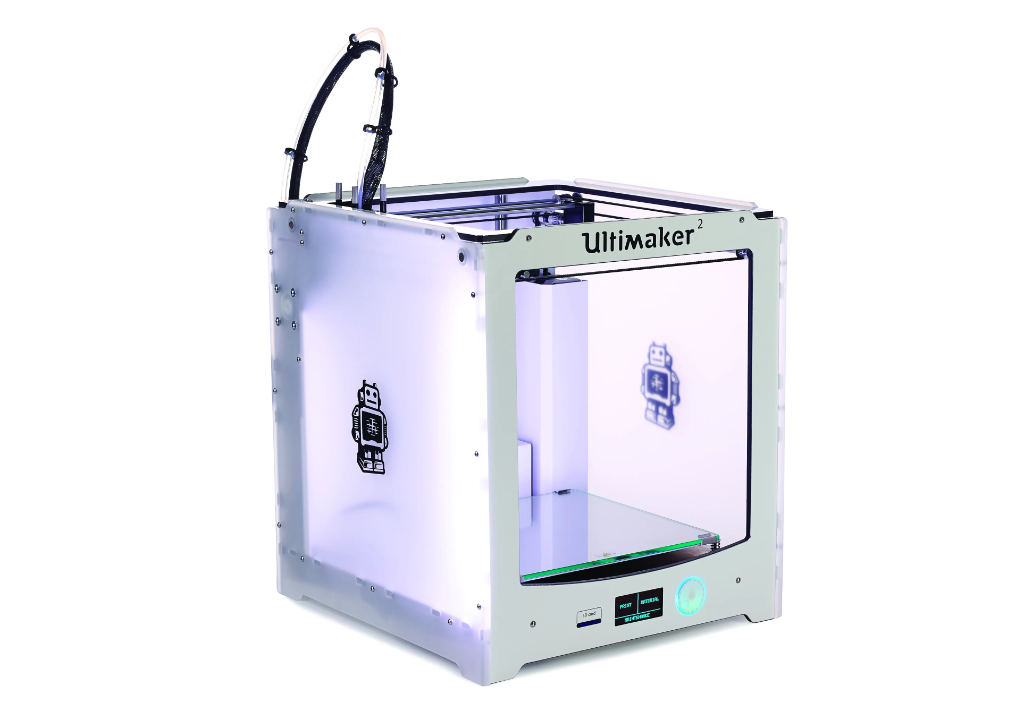
The Ultimaker 2+ is a versatile desktop 3D printer known for its high print quality, reliability, and ease of use. It’s in the higher price range, abd you do get more reliability than the ender. It’s main characteristics are:
Build Volume: 223mm x 223mm x 205mm. Frame: Robust aluminum construction. Print Bed: Heated glass bed. Resolution: Up to 20 microns. Filament Compatibility: PLA, ABS, CPE, Nylon, TPU, and more. Dual Extrusion (Optional): Multi-material and multi-color printing capability. User-Friendly: Intuitive interface with knob-operated control panel. Open Filament System: Supports third-party filaments. Ultimaker Cura Software: Advanced slicing features and compatibility. Community Support: Large user community and regular updates.
Materials
I manily used PLA in my test prints. PLA stands for Polylactic Acid. It is a type of biodegradable (in specific conditions) thermoplastic derived from renewable resources such as corn starch or sugarcane.
PLA is often considered easier to 3D print compared to ABS (Acrylonitrile Butadiene Styrene) or PETG (Polyethylene Terephthalate Glycol) due to several key factors, such as:
-
Lower Printing Temperature: PLA has a lower melting point than ABS and PETG. It typically prints well at temperatures ranging from 180°C to 220°C, making it compatible with a broader range of 3D printers, including those with non-heated beds.
-
Minimal Warping, Stringing and Shrinkage: PLA exhibits less warping, stringing and shrinkage during the printing process compared to ABS and PETG. This characteristic reduces the likelihood of print failures, especially on printers without a heated bed.
-
Minimal Odor and Fumes: PLA emits minimal odor and fumes when melted, unlike ABS, which can produce unpleasant odors and potentially harmful fumes. This makes PLA a more user-friendly option, especially in enclosed or poorly ventilated spaces.
PLA is nice for 3D printing, but every material has its own strengths and best uses. ABS and PETG are tougher and can handle higher temperatures, which makes them better suited than PLA for projects that need durability. So, when picking a filament, it’s best to think about what you’re making, what qualities it needs, and what your 3D printer can handle.
There are many sources of vendors for plastic filaments, but Filipe Silvestre, the Fab Manager at FCT Fablab and my instructor, was partial to Fillamentum and their Extrafill PLA, which he considered to work very well with the Ultimakers and the Ender. That is the material we used on my bigger print, and it was the first time I printer with a material that seemed to have glitter in it. It looked very nice.
Conclusions
3D printing in fused filament deposition has advantages and disadvantages.
Advantages are that it’s a cheap and relatively easy way to materialize complex 3d designs, particularly designs you couldn’t otherwise produce in a subtractive way, like an interior spiral as in my design.
Disadvantages are that it’s a slow process compared to other techniques, as it has to phisically extrude each layer sequentially.
In masked stereolithography printers commonly used today, for example, an LCD screen with UV light sources is employed to project an entire layer of the object onto the surface of the liquid resin, making it a much faster 3d printing technique. Nevertheless I had no access to such a 3d printer this week.
Also, the layer by layer 2.5D process results in comparatively rough surface finish, which you can be made smoother by lowering layer height, but at the cost of even higher time expenditure. There are also strong limitations on what you can print without supports.
3d Scanning
There are several techniques for 3d Scanning, i.e. digitizing physical objects back into the digital realm.
Photogrammetry is the most affordable one, as it consists of taking photographs of an object from different angles, then post processing these in batch, in order to triangulate its features and reconstruct the pointcloud output, by triangulating surfaces from these points.
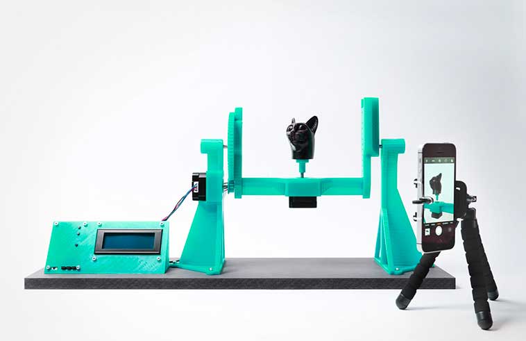
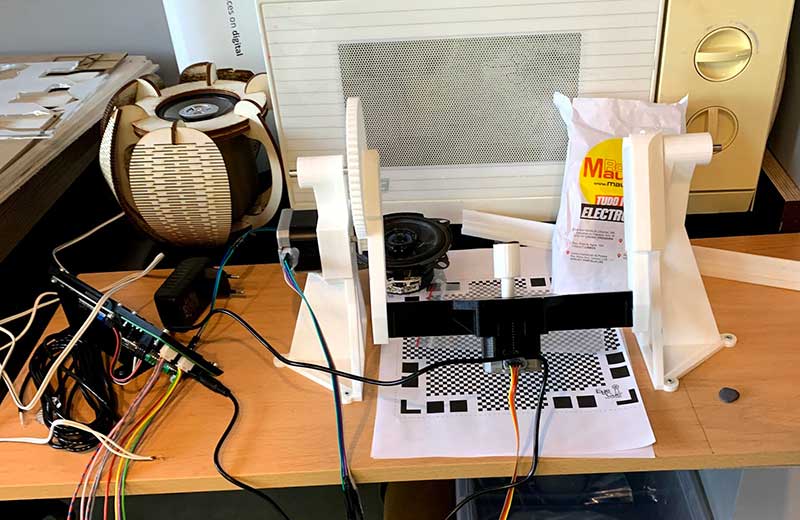
My first attempt started by building an openscanner, which is an open source project of a rig that rotates an object around two axis, while triggering a camera to automatically take a picture at set intervals. I had bought the electronics kit before, 3d printed every part and finally had a chance to assemble it and put it to use.
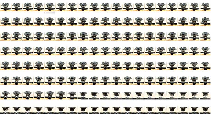
Once all the images were captured and transferred to the computer, photogrammetry software needs to be used to work the images into a 3d point cloud and further processing. This is where I had some trouble, as most free and open source software either needs to be compiled by the user, like Visual SFM, and I don’t have much experience on that, or even needs a Nvidia graphics card that is CUDA enabled, like Meshroom (windows only) or Colmap. None of the computers I have at hand comply with these hardware requirements, as I’m using a mac laptop with an ATI Radeon graphics card.
I tried compiling VisualSFM but couldn’t get it to give any sort of result without spending a whole lot of time researching how to get it to work.
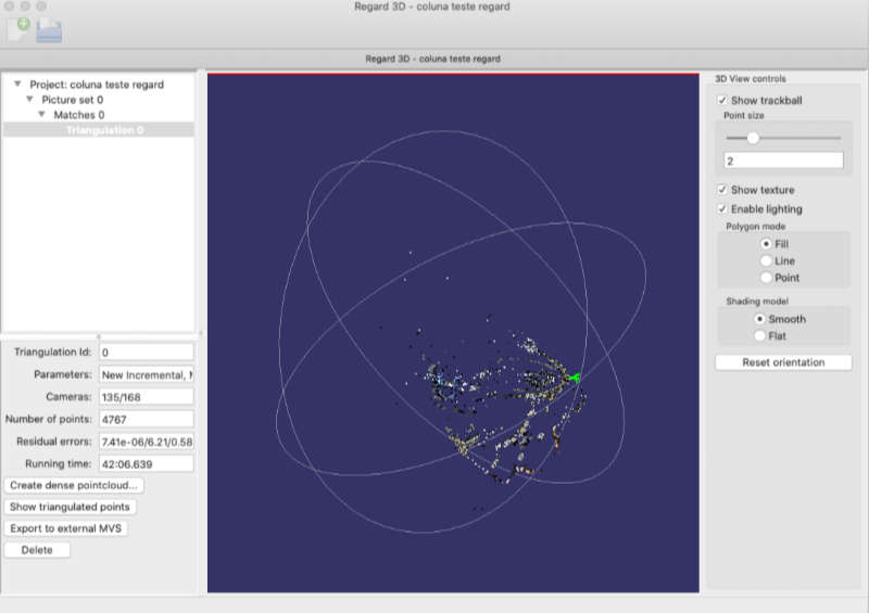
Also tried Regard 3d, but results were less than optimal with the picture set I had.
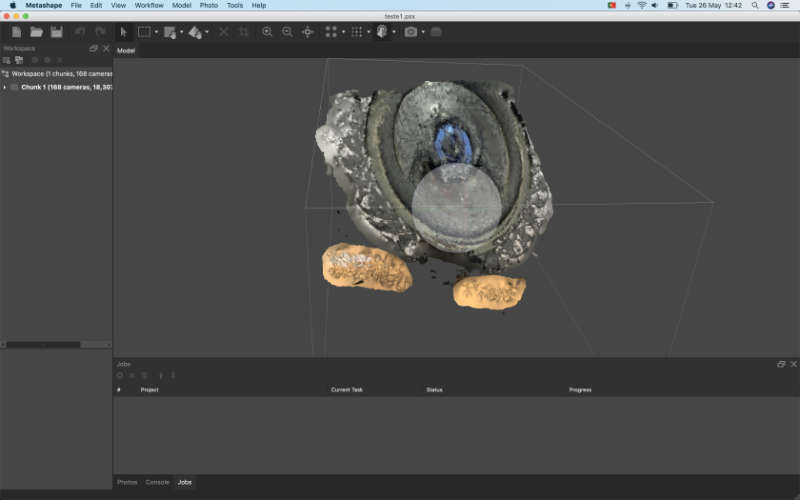
Then I tried Metashape, another free application that works in OSX, with the same picture-set. Results were interesting, but still unusable. I suspect that if I restarted a new picture-set I might get better results, but time was running out. I didn’t finish this week in time and carried on later, but forgot to bring the scanner rig home during the pandemic, so I had no good way of taking a lot of regular intervalled images at nicely regular angles.
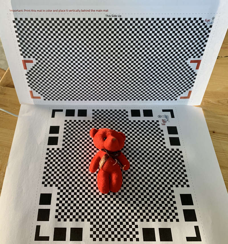
I ended up trying out an app on my phone, Qlone. Qlone offers two template checkered background files that work as reference for the app. I printed these and layed them at roughly 90º, then placed a relatively matte object that offered good contrast and proceeded with the scan as instructed.


In order to download the 3d model, Qlone requires a payment fee, it’s their business model, as with many other similar apps, but I wasn’t willing to pay just for this exercise.
I also tried to use 3d Systems Sense2 handheld scanner, available at FCT FabLab, but couldn’t get it to be recognized by their own software on my computer, either in OSX or Windows 10.
Moral of my experiments: there are many different techniques for digitizing real world objects; photogrammetry is very computationally demanding and most solutions rely on NVidia Cuda hardware on Windows PCs. It is generally regarded as a cheap and viable solution if you have the right tools working and enough time, as well as computational power available. The results are point clouds that are then triangulated to create meshes. It isn’t trivial to get accurate results, as there are no real scale values other than rough estimates based on measuring the objects and scaling the results accordingly. 3d Scanning hardware ranges up in price and capability, versatility and results.
I’m eager to try a solution that works for me, as scanning organic objects, combining them in artistic ways and printing them in SLA could produce really interesting sculptures, something that is interesting to me.
2022
This year I experimented with two other methods of 3D Scanning, which work quite well, depending on what you need. At _ARTERIA_LAB where I work, we have two Artec Scanners, the Eva and the Spider. These are frequently requested for artistic or heritage conservation related scans. I have become fairly proficient with them.
Artec Scanner
Artec is a brand of 3D scanning devices. They’re quite expensive and can yield very accurate models, with submillimeter resolution. Using pulsed light emitted from the device itself, several cameras capture the returning light and calculate the 3d geometry from the objects it shines on, as well as color information.
Their software, Artec Studio, currently runs exclusively on Windows and requires a fairly powerful computer.
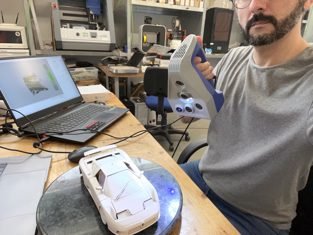
For this exercise I decided to scan a toy car. It was originally painted gloss yellow, but the glossiness made the object too reflective, which makes the scanning very difficult to nearly impossible. One can use a special spray that makes the surfaces less reflective, or hair spray, but I just painted it matte white with a spray can.
I then placed the toy on a lazy susan, a rotating cheese plate I found at home and regularly use for small object scanning. This allows me to rotate the object and keep the scanner at the necessary distance without too much effort.
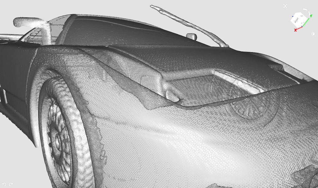
Once I had the car scanned, some processes are needed to generate a mesh that can be exported and altered in other 3d programs, such as Blender, Rhino or Fusion 360. The first thing was to do a global registration, which allings all the captured frames into a more cohesive point cloud.

Next, I usually clean up clusters of points that don’t belong to the main model, like misreadings in the air and the ground plane. For that, I use the eraser tool, which has a lasso selection tool, or a base selection tool, which come in very handy.

Once I’m happy with the alignment, I run what they call a fusion, either smooth or sharp, depending on how much detail I need to retain. This is when a mesh is generated. In this step you can also decide whether you want to make it a watertight mesh, filling any holes with made up surfaces, or use only the scanned surfaces. If one closes every hole, the scan can be opened in a slicer and printed. If not, one can work on the model further and make it printable. I decided to leave it open and use it just for visualization purposes.
I then let the software calculate the texture of the model based on the scanned texture frames from all the scans. This step can take quite some time.
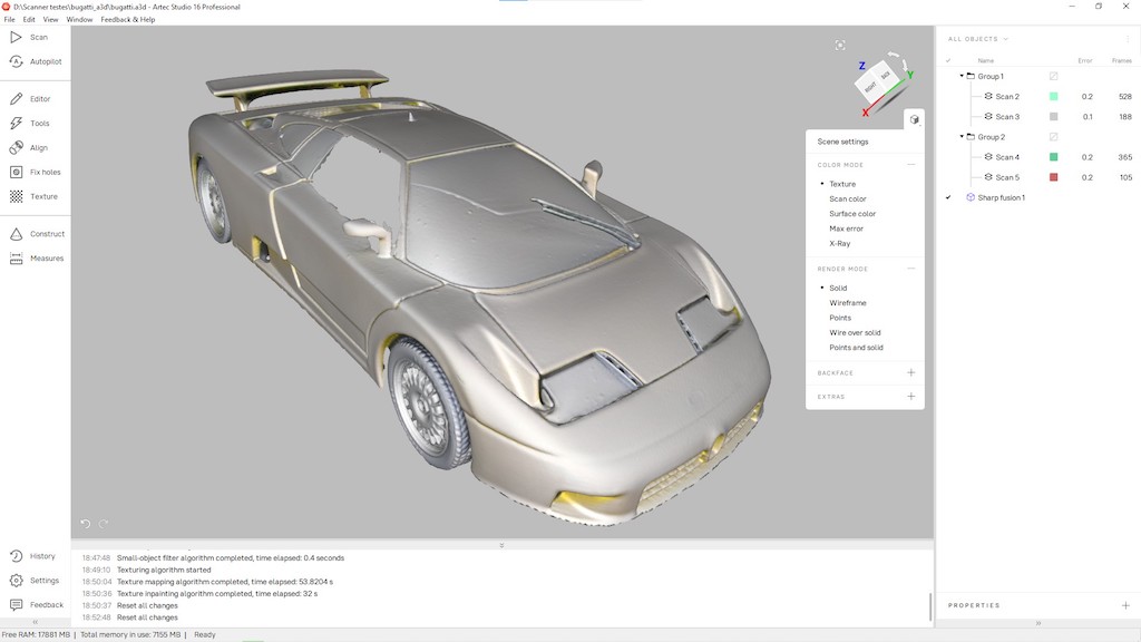
I then exported the mesh and texture as an Obj file, and upload it to Autodesk’s myhub platform as an assembly, where I can share the 3d model as shown below. It’s a nearly 90Mb mesh and it wouldn’t fit in the gitlab repository.
In any case, the resulting mesh can be used as reference to re-model the shapes we want, or reverse engineer some aspects of the model, or even just make parts that fit the model, because the scale is really accurate.
PhotoCatch
PhotoCatch is a photogrammetry app that runs on Mac and iOS. It’s free on the Mac, while on iOS there’s a fee for processing the 3d model, as the computational power is cloud dependent.
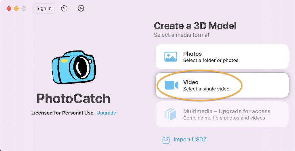
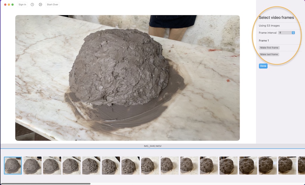
It can ingest a collection of photographs to generate a 3d model, or a video taken from the model, from which it extracts every Nth frame.
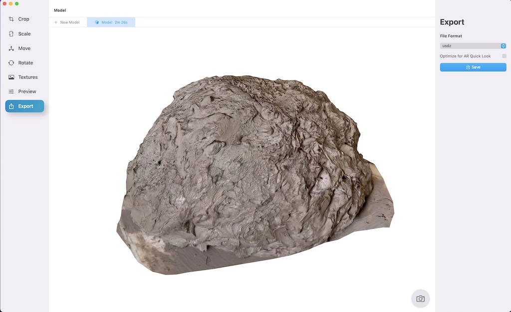
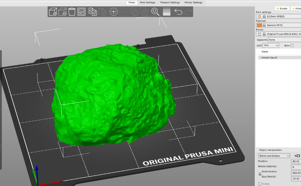
For this exercise, I filmed a pile of clay, very carelessly. I then used it in Photocatch to generate a 3d model that could later be used in a game or 3d visualization setting.
I decided to capture every 8th frame, and use the shown settings.
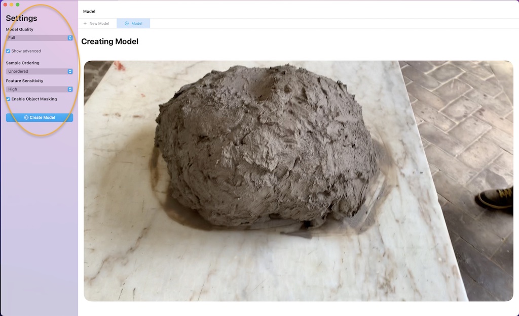
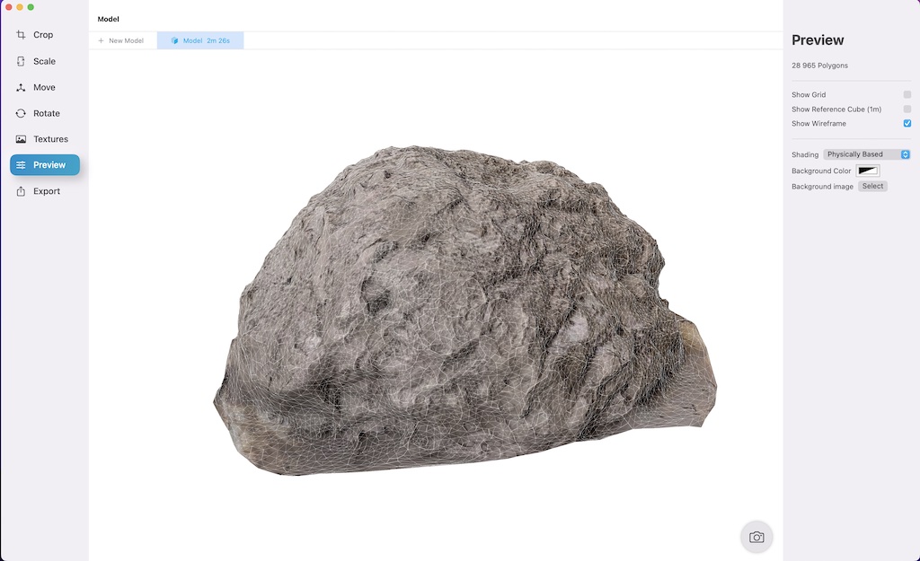
Creating the model took only a few minutes and was fully automated. impressive, considering the result’s I’d gotten in more complex software in 2020, and that it even removed the background automatically.
Here you can see the generated mesh, not very high poly, but accurate enough:
And here is the 3d model, uploaded to myhub.
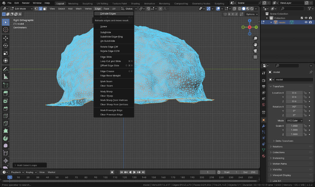
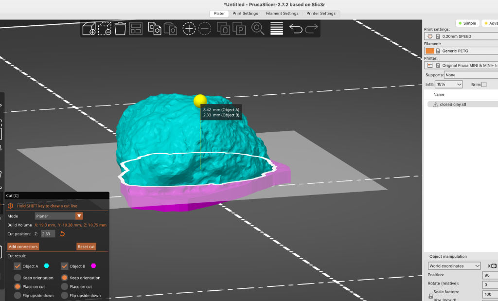
If I wanted to print either of these 3d scan files, I’d have to close them, because as is, they’re only mesh surfaces. In order to do so, I’d either use Artec Studio, in the case of the car model, as it had tools specifically for this purpose, or Blender, which has many tools for the purpose of modeling.
For example, this procedure might be used in the case of the clay pile:


Files
Subwoofer enclosure in STP format for size reduction and retained editability.
Scanned toy car in STL format, deprecated and without textures, for size reduction.
Scanned pile of clay in OBJ format, without textures, for size reduction.
Checklist
Group assignment
- Test the design rules for your printer(s)
- Document your work and explain what are the limits of your printer(s) (in a group or individually)
Individual assignment
- Design and 3D print an object (small, few cm3, limited by printer time) that could not be easily made subtractively
- 3D scan an object, try to prepare it for printing (and optionally print it)
Learning outcomes
-
Identify the advantages and limitations of 3D printing
-
Apply design methods and production processes to show your understanding of 3D printing.
-
Demonstrate how scanning technology can be used to digitize object(s)
Have you
-
Linked to the group assignment page
-
Explained what you learned from testing the 3D printers
- Documented how you designed and made your object and explained why it could not be easily made subtractively
- Documented how you scanned and prepared an object (for 3D printing)
- Included your original design files for 3D printing (original CAD and STL are too large, so common STP format only)
- Included your hero shots
Group assignment
-
Test the design rules for our printer(s)
-
Document your work and explain what are the limits of your printer(s) (in a group or individually)