Electronics Design
Group Assignment
For the group assignment, please refer to out Electronics Design Group page
Individual Assignment
Redrawing a hello-world board based on Amtel Attiny44
This week I started drawind a hello world board based on Attiny44 in Eagle, continuing the workflow of electronics design week.
I followed Neil’s examples in order to identify the needed components and design a single sided board, as that is the most viable option at FCT Fablab. I added a button and 3 LEDs, hoping to develop a simple one button game. I also added a debouncing circuit in order to prevent noise when connecting.
 |
|---|
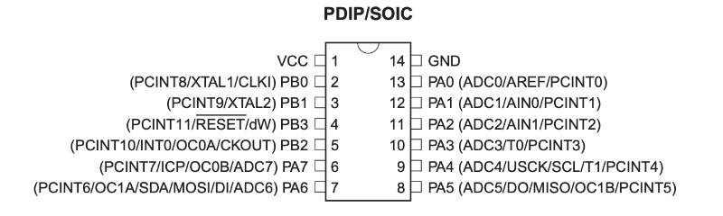
| Atmel Attiny44A pinout, from Attiny44 Datasheet |
 |
|---|
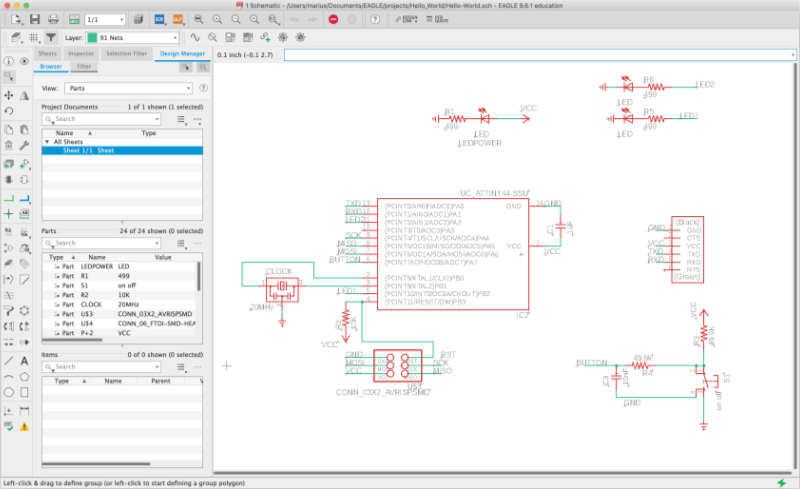
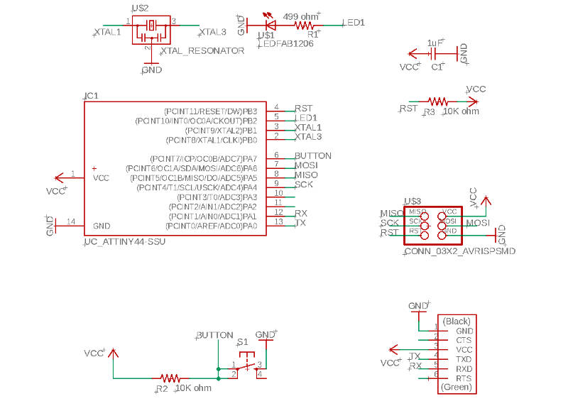
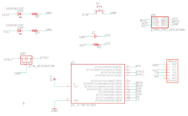
| first hello world board design schematic |
 |
|---|
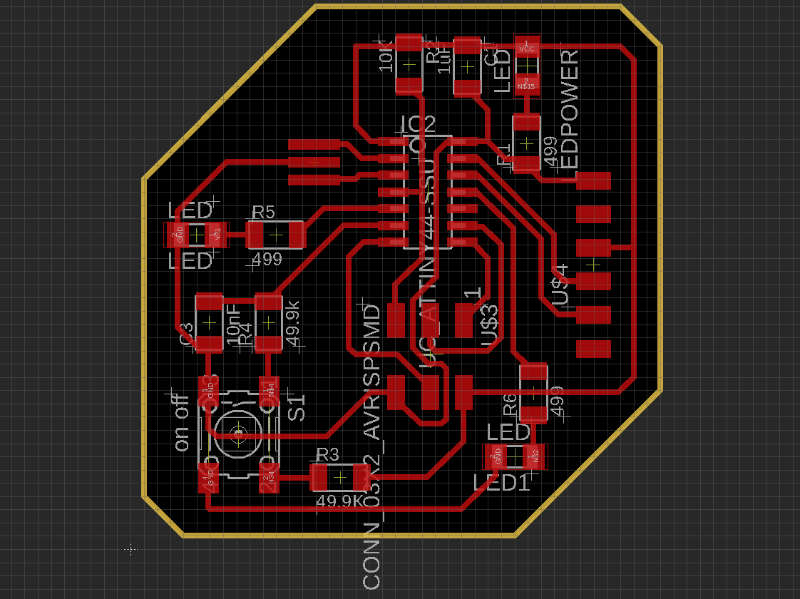
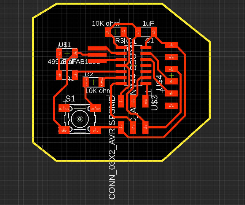
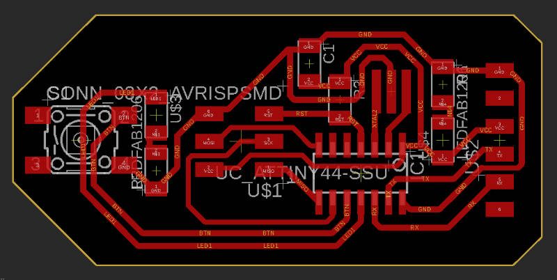
| first hello world board after routing vias |
 |
|---|
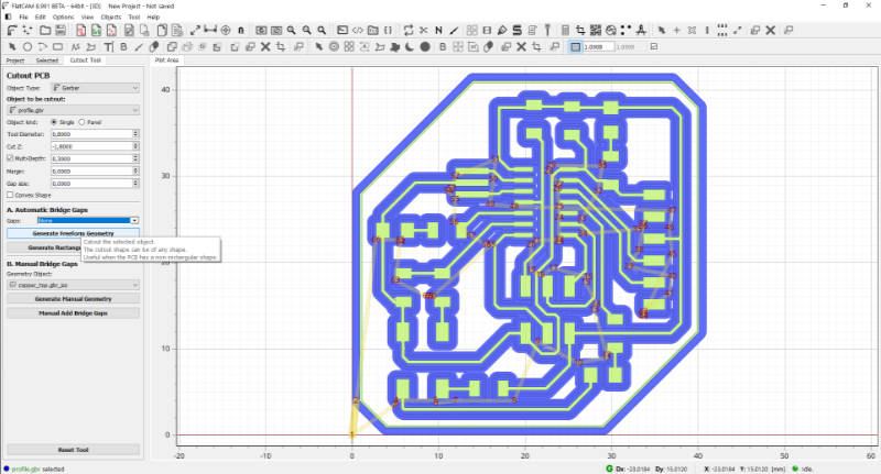
| preparing board in Flatcam for milling |
 |
|---|
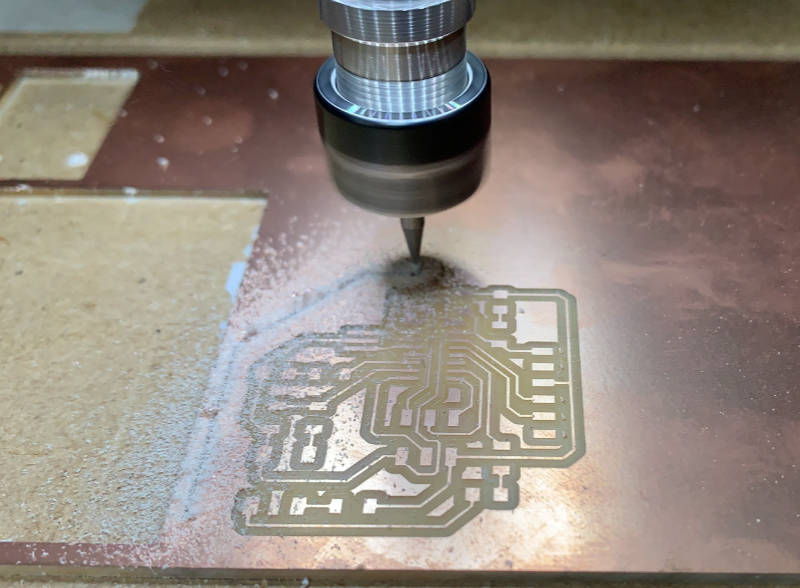
| milling my first hello world board |
 |
|---|
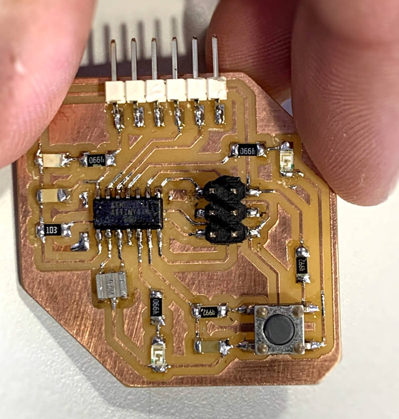
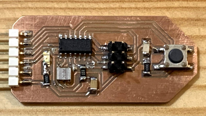
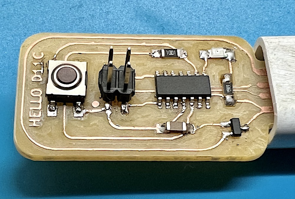
| hello world board populated |
Even though my soldering skills are still quite subpar, when checking with a multimeter, all connections seemed solid and there were no shorts.
Then I connected my FabTinyStar AVR ISP to the hello boards pinheaders, and the other pins to the usb cable for power.
I then followed these instructions, but couldn’t get the board to accept the programming of the fuses, exiting with error code 1.
 |
|---|
| ftdi instructions |
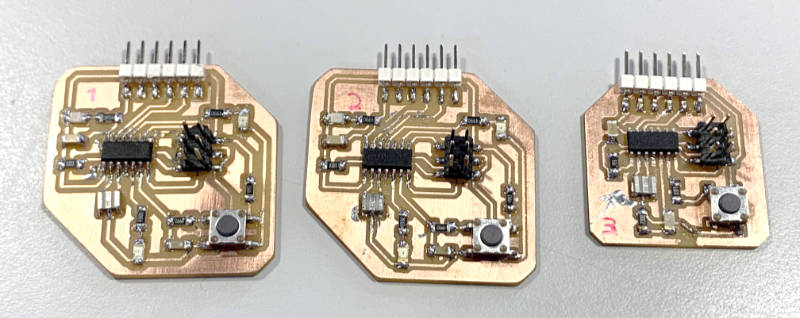
So we began toubleshooting. My programmer from week 4 was being recognized on my mac, but it had never worked for programming anything else, so that came to mind first. Filipe Silvestre and I tried a known-to-work programmer from the fablab, but had the same error. I also thought it could be my soldering, as the oscilator was really hard to solder right. So I started milling another board and populated that one too, but it didn’t work either. I then simplified my design in Eagle, removing 2 of the extra LEDs and the debouncing part of the circuit, as I thought I might have been too ambitious for a first board.
 |
|---|
| second Hello Board schematic |
 |
|---|
| second Hello Board schematic |
 |
|---|
| second Hello Board schematic |
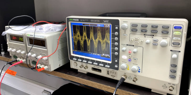
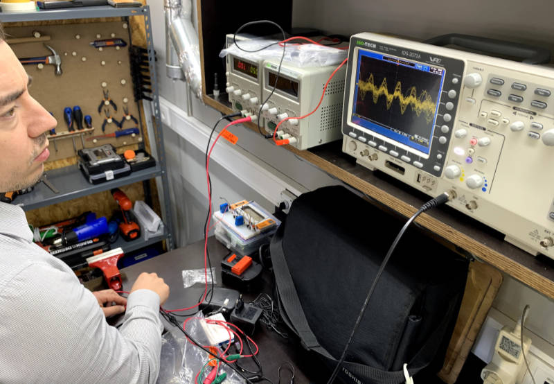
That board didn’t work either! UGH!! We were out of ideas. With Luís Carvão on video-call
we connected the last Helloboard to the oscilloscope, and could measure a whole lot of electric noise!
 |
|---|
| Circuit noise on the osciloscope |
 |
|---|
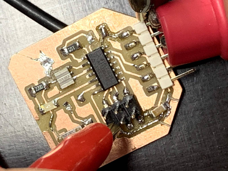
| on this image I had already removed a capacitor from ground and added one between ground and vcc to mitigrate noise |
 |
|---|
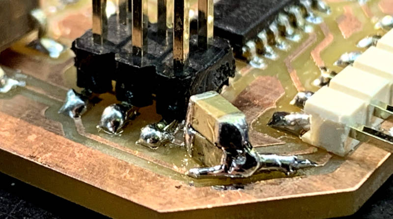
| As noise was going down, but still not completely, I added another capacitor on top of the other |
 |
|---|
| Less noise on the osciloscope |
But still no luck programming the Hello Board. By this time we were using Atmel ICE as the programmer, so that couldn’t be it either.
Maybe I had designed the boards too large, for ease of soldering the tiny SMD components, so maybe the vias were acting as radio frequency antennas, maybe my soldering was really bad? It seemed solid. On a last effort, Filipe Silvestre gave me his hello board design from when he attended fab-academy, so I milled and populated that.
 |
|---|
| Filipe’s board schematic |
 |
|---|
| Filipe’s board design |
 |
|---|
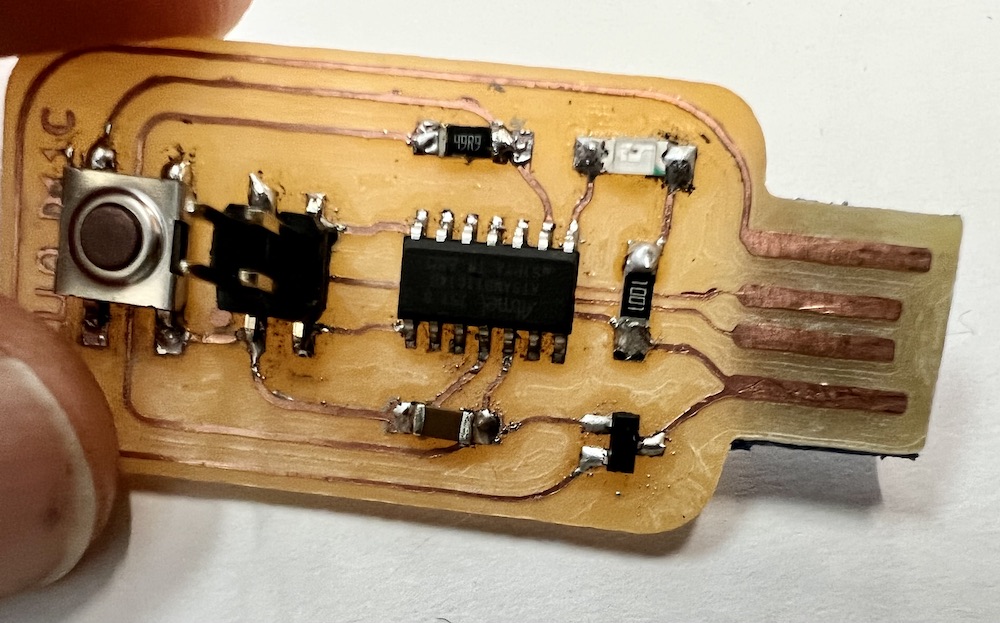
| Looks neat and my soldering is getting better |
Time was running out as we had to leave for Covid19 confinement. I was lent the Atmel ICE and went home with all the boards.
On the next tutoring session with Luís Carvão we tried debugging the board, as even this one could not be programmed.
 |
|---|
| programming hello board with Atmel ICE at home |
Turns out a few things were messing up the process. One was that my mac running OSX Mojave had a protection that prevented a kernel extention from loading, which was necessary to send data through. So I had to (…)
Also, When Filipe Silvestre bought the last batch of Attiny44, he didn’t realize he was buying a newer version of the chip, the Attiny44U (? - check this)
(compare pinouts from datasheets)
Chips were labeled “old” and “new”, I didn’t realize there was a difference, and used one or the other intermittently. This was a problem we identified later, as when we finally managed to get OSX to let the ICE push code to my hello board, the chip wasn’t recognized. We altered the (?) file to include this (?) chips signature, but then realized the pinout had changed between versions! that explained a lot, but I was stuck once again, now without a soldeting station or a way to mill a new pcb!
This whole process happened accross the span of much longer than the week it was supposed to, going well into pandemic times.
FAB SWD Programmer
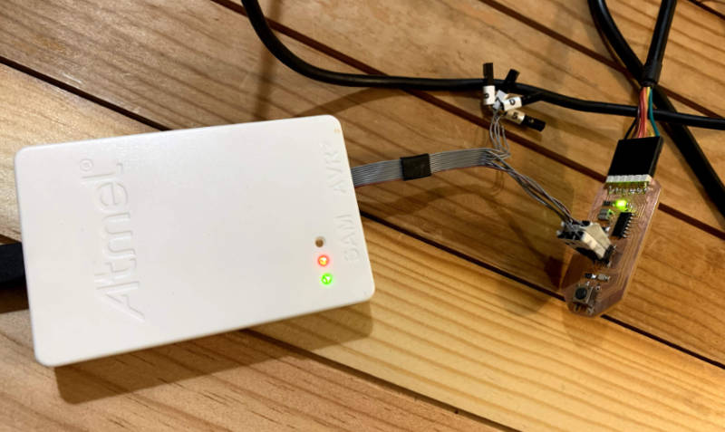
Continuing the quest I’d set for electronics in 2022, I had just finished setting up my FAB SWD programmer with the Atmel ICE at FCT FabLab. I had made a simple SAMD11C hello board, and it was now time to test my programmer.
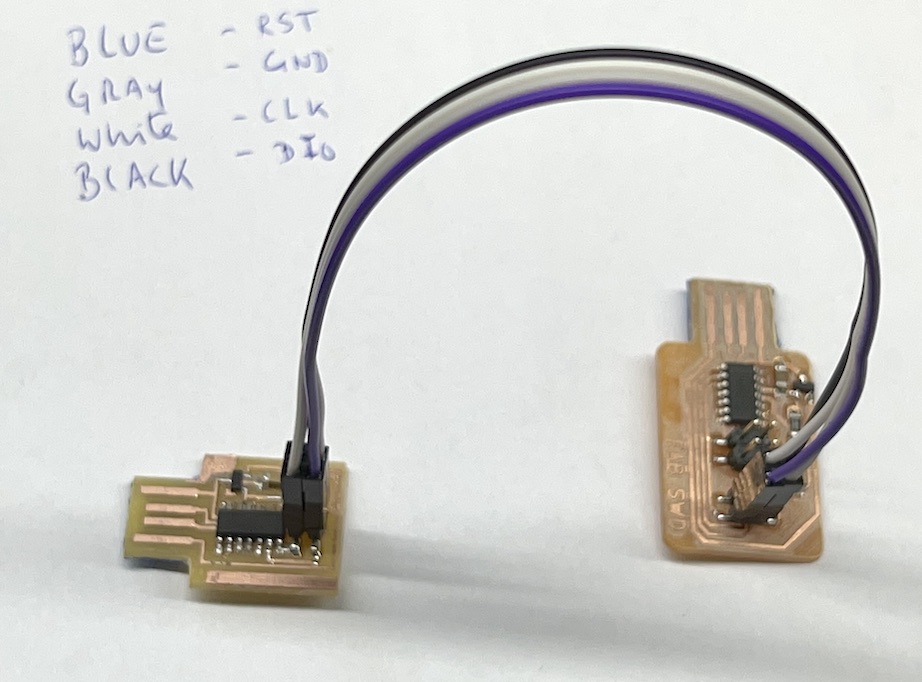
I connected the JTAG connectors in both boards with jumper cables, making sure they corresponded propperly.
In order to program the hello board, which also has a SAMD11C microcontroller, I would flash a bootloader that allows the board to be programmed with Arduino IDE, the so called Fab SAM Core. To do so, I followed Quentin Bolsee’s instructions again and downloaded the required .bin file from here.
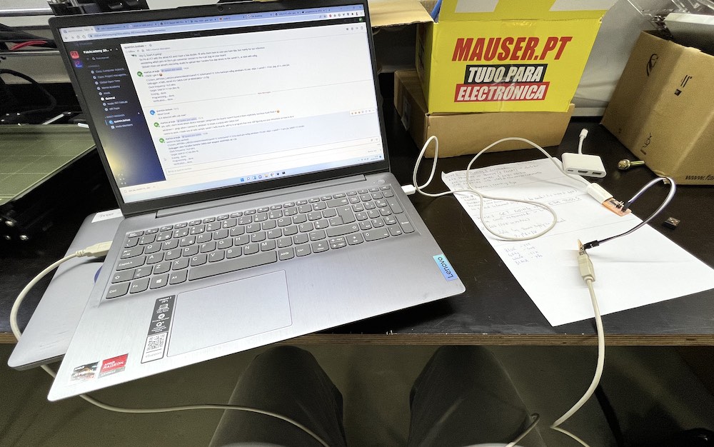
Then I connected both to usb extensions and to my computer, and ran the command to flash. The result was quite quick. Awesome!
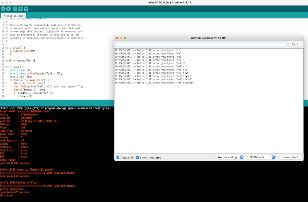
C:\> edbg-windows-r32.exe -ebpv -t samd11 -f sam_ba_SAMD11C14A.bin

Debugger: Alex Taradov Generic CMSIS-DAP Adapter ADEFF95D v0.1 (S)
Clock frequency: 16.0 MHz
Target: SAM D11C14A (Rev B)
Erasing... done.
Programming.... done.
Verification.... done.
To test my new hello board, I openend Arduino IDE. In order to enable Arduino IDE to program to it, I added this URL to the Additional Boards Manager:
https://raw.githubusercontent.com/qbolsee/ArduinoCore-fab-sam/master/json/package_Fab_SAM_index.json
Then, in the Boards Manager, I searched for FAB and installed Fab SAM core for Arduino. Once that was done, I could chose the Generic D11C14A board from the list.
I then pasted Neil’s Hello World code into a new arduino sketch and pressed upload. Opening Serial Monitor, I wrote Hello World and the board replied:
I asked Quentin on Mattermost if I could use the JTAG pins to test out a simple blink program, and he replied that “You can blink the DIO pin, it’s safe to do that”, so I pluged in an LED from my instructor Filipe Silvestre, to the DIO and GND pins. I then opened the blink example Sketch and changed the led pin to PA31. I checked the SAMD11 Datasheet and figured the DIO pin was connected to that pin in the board, so that should be the reference I needed.
It was blinking! Great!
Hello SAMD11C
Now it was time to redraw a Hello Board and add an LED and button. So far I had only coppied other peoples designs (standing on the shoulders of giants) but now I had to make my own. I won’t pretend I know what I’m really doing yet, so I thought I’d start by referencing another board and try to make the changes I needed to it.
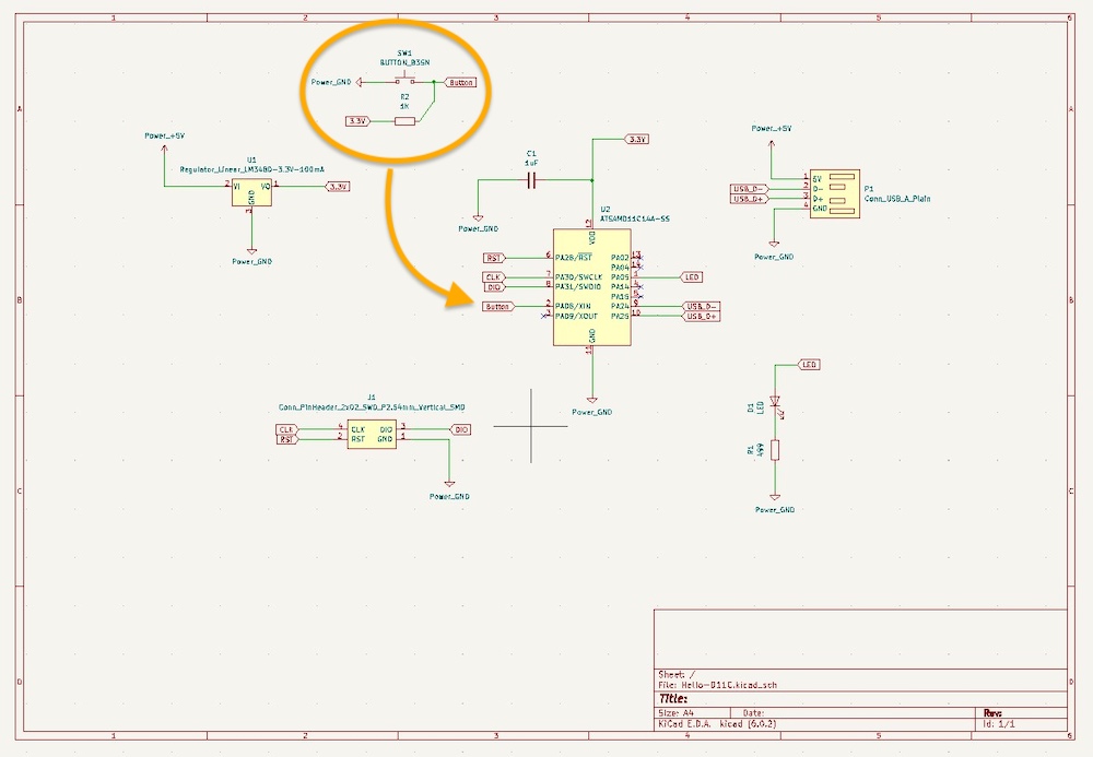
I went back to the Programmers Summary page and decided to start with Krisjanis Rijnieks Hello D11C Board. It had the same JTAG header I used in my two previous boards, so I was confident I could program it too. It also already had an led, so I just had to add a button.
KiCad
I had started using KiCad in Electronics Production week, but it’s worth mentioning how I prepared it to work with the Fab Academy component library, which is important when most of the parts one has are from that list. I installed KiCad and then followed Krisjanis Rijnieks’ instructions on the gitlab repository:
Krisjanis’ instructions
- Clone or download this repository. You may rename the directory to fab.
- Store it in a safe place such as ~/kicad/libraries or C:/kicad/libraries.
- Run KiCad or open a KiCad .pro file.
- Go to “Preferences / Manage Symbol Libraries” and add fab.kicad_sym as symbol library.
- Go to “Preferences / Manage Footprint Libraries” and add fab.pretty as footprint library.
- Go to “Preferences / Configure Paths” and add variable named FAB that points to the installation directory of the fab library, such as ~/kicad/libraries/fab or C:/kicad/libraries/fab. This will enable the custom 3D shapes to be found.
He also has a very nice KiCad introductory video on youtube, which I followed as well for completion
I cloned Kris’ repository and opened it in KiCad. I started by adding a button in the schematic and connecting it to a free pin on the microcontroller. I also added a resistor between the button and Vcc, in order to create a pull up. Quentin later explained that a pullup is unnecessary because the SAMD11 already deals with it internally, but I didn’t know that at the time.
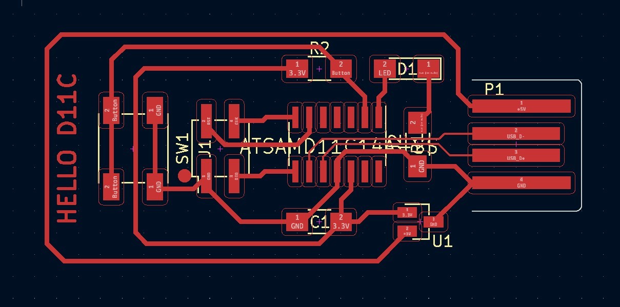
I then started reorganizing the components on the board. for this I had to break the edge cut, but I’d make a new one one the user layer.
One thing that I learned is that you can make curved tracks in KiCad, by installing a plugin aptly called Round Tracks.
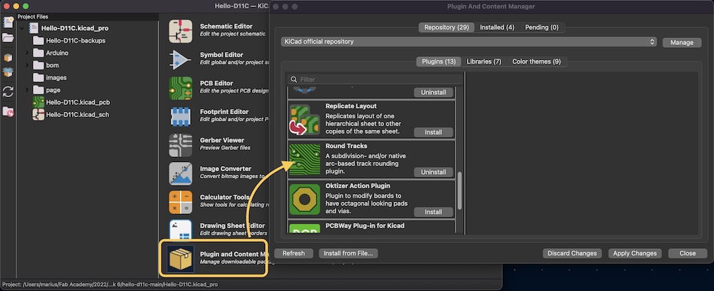
The designer in me loves scurves. One has to give enough space for the tracks to be rounded, as the plugin seems to ignore some design rules, like keeping distance from component pads and other tracks, but if we take care, it works and looks really nice.
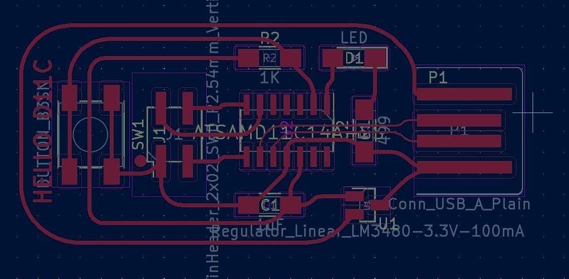
Once I was happy with the design of the vias, and KiCad was ok with ERC, I turned on a user layer and drew a shape that would represent the edge cuts. I did make a suitably sized rectangle, but I spent way too much time maing that and wasn’t even happy with the result. I knew I sould draw something much nicer in Inkscape, much faster. And considering I was going to Mods with to produce the GCodes again, it seemed perfectly natural do just do the board edges there.
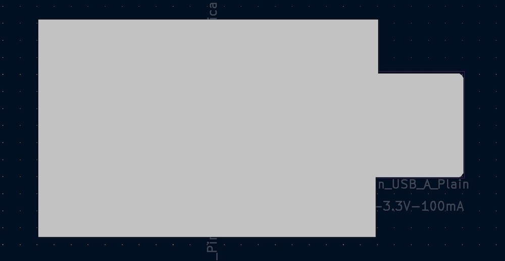 My best edge in KiCad ^
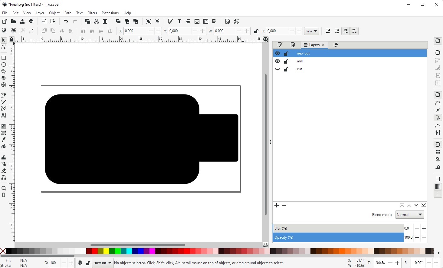 A decent edge in Inkscape ^
Here’s my .SVG file from inkscape; it’s layer separated for ease of export.
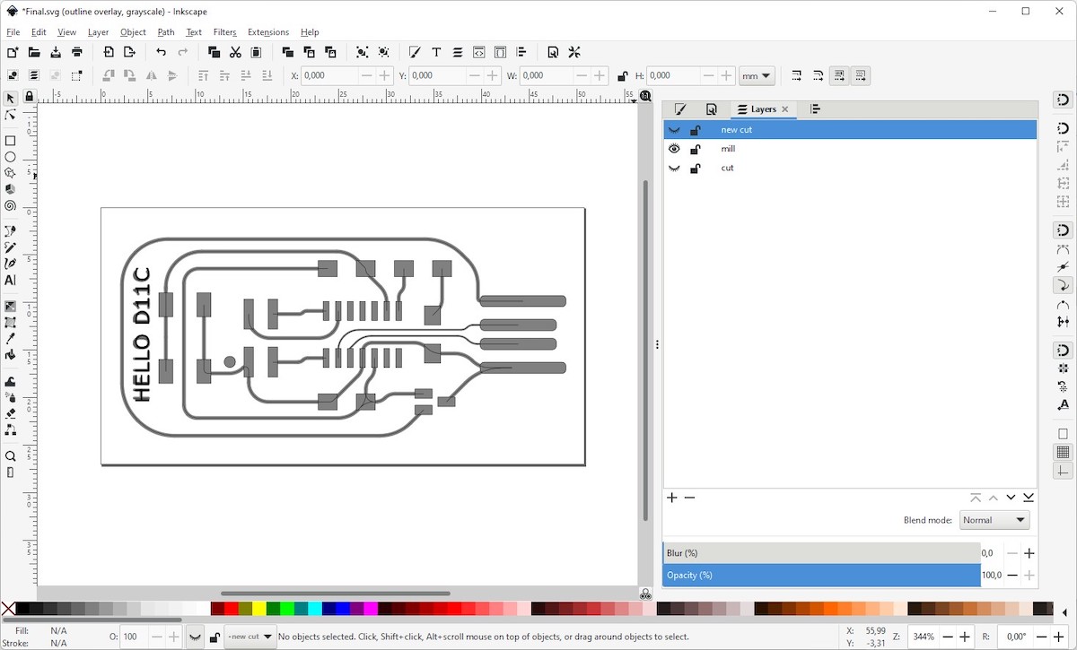
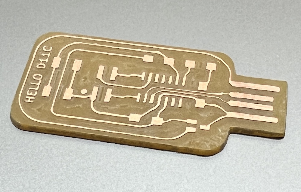
I then exported the copper traces and egde cuts as separate svgs, used Mods just like in Electronics Production week to generate the GCode files, then used Candle again to send those GCodes to my 3018 CNC. The result was pleasing, especially after many mistakes that taught me to be more careful and awake when milling boards. There were a few spots to clean by hand still, but after a bit of scalpel action, this is what it looked like:
And here is what it looked like when poppulated with all the components. Try to spot the mistake that plaged me shortly after.
So now it was just a question of flashing the Fab SAM core with my programmer, and start pushing some code with Arduino IDE. The flashing went fine, so then I proceeded as before, and as before, I opened the Blink example sketch, inicialized pin 5 as output pinMode(5, OUTPUT); and sent it to the board. But nothing seemed to happen. Arduino IDE said it sent ok, but no blink. I confirmed with Quentin that it was the right pin. He refered me to this documentation, which explains a lot more than I can here, but basically that was not the issue. He very kindly spent some time troubleshooting the issue. I used a multimeter to check the orientation of the LED, the continuity of all the vias and pins, and finally even managed to measure that there was a voltage drop at regular intervals.
That demonstrated that the program was working, just not allowing enough current to light the LED… Then Quentin noticed the resistor to the LED was waaay too low! For some reason I’d mistakingly put a 49.9 Ohms resistor to the LED, which might have fried the GPIO pin on the processor, having allowed too much current to flow through it.
Quentin suggested I swap the resistor for a 1K Ohm and try again. I didn’t have my components on hand at the time, but I wan’t using the button, so I dessoldered the 1K pull up resistor and swapped the other one.
After replacing the resistor, I could still measure the voltage drop, but no light from the led. So I took Quentins next suggestion: “if it’s broken, cut the track to the pin and use a short wire to connect to another”. Microprocessor bypass surgery. Ok, I didn’t have much to lose XD
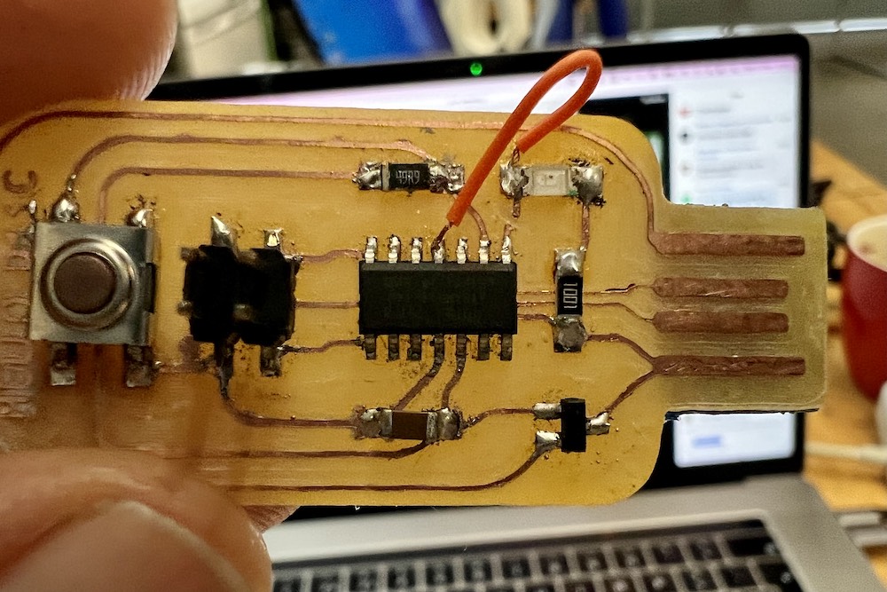
Who would have thunk it?! Worked!
(mis)Calculations of LED current limiting resistor value
A comment from my remote evaluator, Suhas, on documenting how I calculated the LED’s resistor value, made me think.
I didn’t calculate the resistance on the LED because it was already in the original bill of materials from Krisjanis’ Schematic, 499K Ohm, but had I had to, I’d follow this handy guide which states that when computing the value of a current limiting resistor for a single LED, the basic form of Ohm’s Law, V = I x R, becomes:

where:
- Vbatt is the voltage across the resistor and the LED, which in my case, comming from the regulator, is 3.3V.
- Vled is the forward voltage of the LED, which according to the LED’s datasheet is 1.8V typically, 2.4V max.
- Iled is the forward current of the LED, which also according to the datasheet, is 40mA (or 0,04A).
In my case then, would result in a resistor of 37.5 Ohms. This, if I had the exact same LED, which I suspect I didn’t. I made a mistake when soldering the resistor, and used a 50 Ohm one, which according to this calculation, would have been safe as it was above the calculated value. That was too low not just for the LED, but also for the SAMD11C, as I burned a pin. Fortunately, and with Quentin’s orientation, I was able to swap the resistor for a 1K Ohm one, and use another pin to salvage this board, blinking the LED fairly brightly, still. My reasoning must be wrong somewhere, but it seems that the LED I used had a forward current of 1,5mA, and not 40mA… could this be?
ERC / DRC check
The electrical rules check (ERC) automatically verifies your schematic connections. It checks for output pin conflicts, missing drivers and unconnected pins. It helps verify connections on the schematic before proceeding to the board design.
The Design Rules Check (DRC) automatically verifies that a set of board design rules have been adhered to. These rules include track width and clearing, lenght, it verifies that electrical connections are according to the schematic, and it’s an important part of verifying if our design is manufacturable. In our case, because we are going to mill the traces on a cnc, it’s important that clearences between tracks and component pins are millable with our mills and that there is enough copper on the pads to be able to solder the components by hand.
Files
My Hello SamD11C Kicad files, zip compressed
Arduino Sketch
Checklist
Group assignment
- Use the test equipment in your lab to observe the operation of a microcontroller circuit board (in minimum, check operating voltage on the board with multimeter or voltmeter and use oscilloscope to check noise of operating voltage and interpret a data signal)
- Document your work (in a group or individually)
Individual assignment
- Redraw one of the echo hello-world boards or something equivalent, add (at least) a button and LED (with current-limiting resistor) or equivalent input and output, check the design rules, make it, test it.
Learning outcomes
- Select and use software for circuit board design
- Demonstrate workflows used in circuit board design
Have you?
- Linked to the group assignment page
- Documented what you have learned in electronics design
- Explained problems and how you fixed them, if you make a board and it doesn’t work; fix the board (with jumper wires etc) until it does work.
- Included original design files (Eagle, KiCad, - whatever)
- Included a ‘hero shot’ of your board
- Loaded a program and tested if your board works