Computer Aided Design
I skipped this week in 2020 because I had a work trip that was planned before I knew I was doing fab-academy. When I returned I started working on Computer Controlled Cutting and for one reason or another I ended up not documenting this week, probably the general pace of the course. By now (2021) I’m confident I know what my Final Project is and will be demonstrating how I used Rhino and Fusion to model the head of my final project, and the thought process that went into that. I have a Ba in 3d Computer Visualization and Animation, so I’m confortable with a few 3d modeling programs, but these were what I used most during Fab Academy.
3D Modelling
I started off in Rhino, where I’m currently most comfortable modeling.
I had a reference model of luxo jr that’s freely available on thingiverse, by user Daniel Bull. I imported the stl files into rhino, so I could re-model and make it my own model, as well as add important details.
NURBS
Rhino is mainly a NURBS modeler, which means that geometry is described by Non-Rational Uniform B-Splines, or curved vectors in short. Unlike meshes, used in STL or OBJ files, which connect vertices with one dimensional vectors (straight lines), NURBS are multidimensional vectors that allow for infinite curvature without loss of surface detail. One analogy of the difference between meshes to nurbs is to compare raster to vector images; just as with digital photos if you zoom in enough you can see the pixels, in a mesh model you can see the individual vertices and connecting vectors, as the surface is described by triangular or quadrangular patches. NURBS really are vectors, on n-th degree, used to delimit the surfaces of the model.
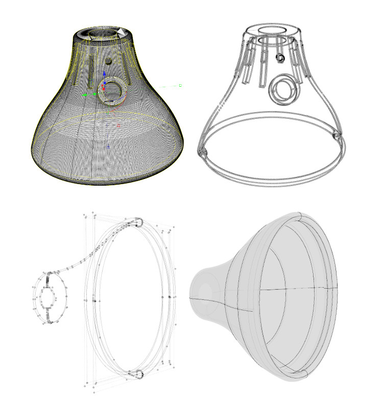
I started by using a command in Rhino that extracts vectors from geometry. The new vectors are very dense in terms of control vertices, because the original geometry is very dense. That isn’t ideal, but in my mind, it helps as reference.
Then, I set away at drawing new vector splines for the main features of the model, with the help of several object snaps, which are like magnets for certain features, like vertices, end points, quadrants, center, etc. which are very helpful in Rhino. Using 3 point circes, splines, and commands like revolve, extrude and loft, I drew the outside surface, then copied and scaled it in to create the inside surface. Offsetting surfaces doesn’t always work well in Rhino, so I found copying and scaling to be a simple workaround. Then you have to create the joining surfaces between the outside and inside surfaces, in order to make a water-tight volume.
On modeling for 3d Printing
That is very important, because if you want to print a 3d model, the slicer that prepares that model for printing uses ray tracing to determine what is inside and outside of the model, to generate the appropriate walls, infill and outside support, if needed; if the model is open somewhere, that can generate confusion as the rays need to go through pairs of surfaces to complete their journey, otherwise the slicer might determine to generate infill on the outside of a part, or support on the inside. Most slicers already compensate for small mistakes, but it’s good practise to be accurate in the modeling stage.
The resulting geometry is clean, light, and easy to look at. I kept most of the shape except for the rectangular holes in the back, which in a lamp are useful to dissipate heat, but I thought they didn’t make sense in a speaker, as I want to retain just one whole to bass to escape out of the back.
At this point I knew I had to model a new neck, as the speaker I chose, a 4” Dayton Audio RS100-4 full range driver, weighs 583g (nearly 1.3 pounds). That makes the model quite top heavy and since I was planning to 3d print this part, the neck and shoulders would need reinforcement.
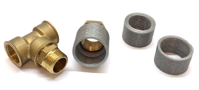
I went to a hardware store to try and find metal parts to reinforce my 3d print, and after some search I decided to get some hydraulic pipe brass fittings.
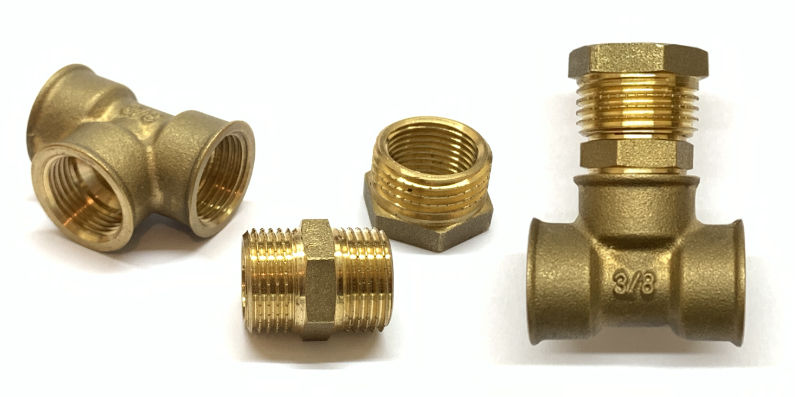
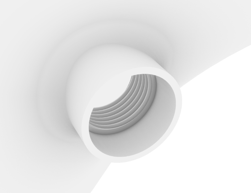
So to integrate these parts into my model, I had to make threads. Rhino is great and light and nice looking, but a parametric modeler it is not, and modeling threads is no fun there. I know, I’ve done it. It’s ok for visualization purposes, but not so much for actually fitting parts together. I resorted to Fusion 360 for this.
After measuring my brass fittings, I started by modeling a 26mm diameter, 22mm tall cylinder. I then used the Solid > Create > Hole to create a section for the thread, and another to hide part of the brass that connects to the shoulders. For the thread, Solid > Create > Thread brings up the settings, where you chose the section you want the threads in and some predetermined thread sizes. Here, to be honest, I needed a few iterations to find the right parameters. I would choose what seemed closest to measurements, export the body as an STL file and print it in the fab-labs Ultimaker 3d printer. Test, adjust, and try again.
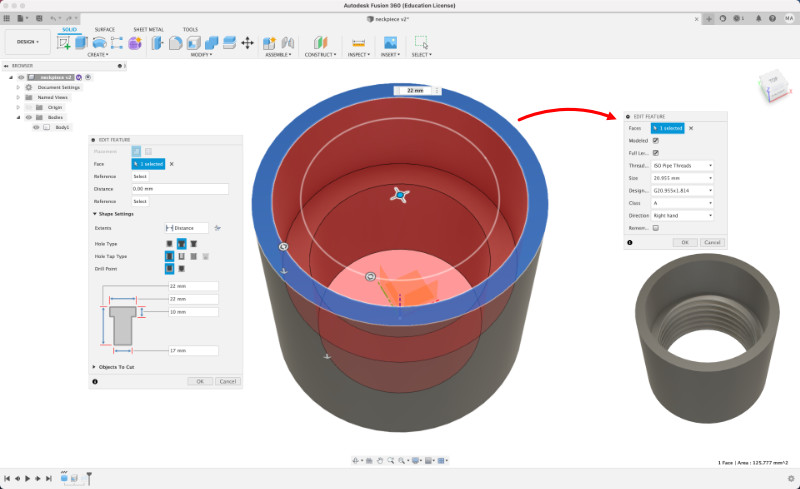
I ended up settling for 20.995mm ISO Pipe Threads, and it finally fit nicely.
Once I was satisfied with the fitting, I exported the model as STEP from Fusion 360 and imported it into Rhino, where it was recognized as NURBS geometry and I carried on integrating it into the rest of the model. I placed it similarly to my reference design, adding some nice fillets to strengthen the connecting surfaces.
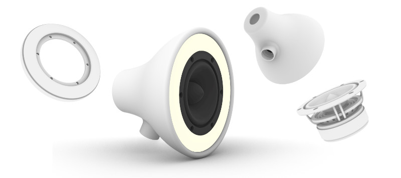
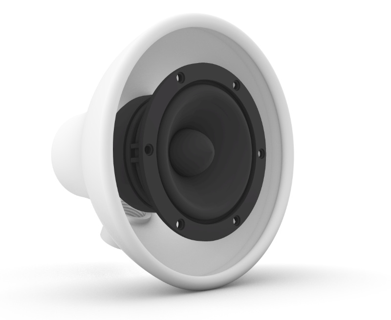
The way I wanted to place the driver was to make an oculus, a sort of translucent ring around the driver that would fix it in position and allow for light to pass through. To model this element I would need the drivers accurate dimensions. I found a datasheet for the driver, where there was a schematic with some measurements. It was useful, but I grabbed my calliper to confirm those measurements and take many more.
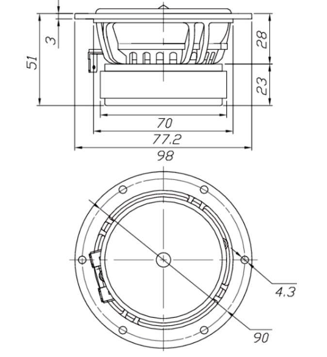
It took a good while, with so many details, but I was satisfied with the result. It’s not 100% accurate, but where it matters, it matches the physical version.
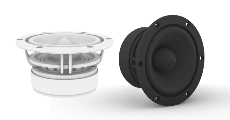 |
|---|
| Dayton Audio RS100-4 3d model |
I then finally centered it with the head model and with both as boundaries, I modeled the Oculus for the ring light.
 |
|---|
| ready to model Oculus, the Ring light element |
This part was meant to be translucent, so I was planning to either sla 3d print it with transparent or white resin, or cnc machine it out of HDPE, a plastic I know lets light through if it’s thin enough. So I made sure I made the middle part thin enough. I hope 2mm isn’t too much, but I do need some thickness so that the part isn’t too fragile with the driver in place.
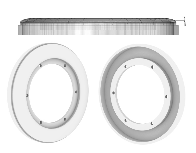 |
|---|
| Oculus, the Ring light element |
Finally, I had to split the front of the head piece, so that I could actually mount the ring light and driver assembly into it.
I split the head at the front lip, so that the ring would become wedged on the shell and secure by the lip piece.
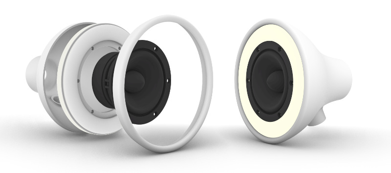 |
|---|
| All the 3d modeled elements of Speaker Bestial |
I don’t totally trust friction to hold the weight, so I’ll make a metal bracket between the threaded brass part and the back of the driver, where there is a hole I could thread to screw the bracket into. But for now, this will do.
2D Design
Before Fab Academy I had had experience with Adobe Illustrator and Corel Draw, but since I started working in a fab lab, I’ve learned more about Inkscape and have grown to like it quite a lot, so much so that I do most of my 2D work on it now and even give summer school classes on it.
For my final project, I wanted to cut parts from scrap acrylic I had. I regularly use inkscape with our laser cutter, as it’s really easy to visualize hidden curves with X-ray mode, to set the right propperties for cutting or engraving, and becauser it’s generally a great vector editting software. I started off in Rhino, where I do 3d work, redrawing 2D curves from the 3D parts of the Fab Speaker’s body. There are a few different parts, although fairly simple ones.
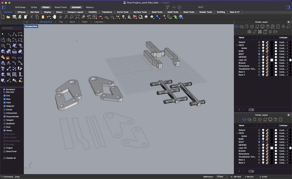
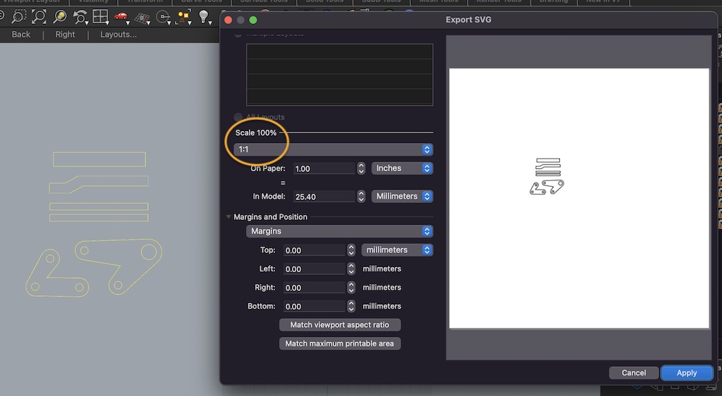
I exported them as SVG from Rhino, making sure to keep the scale at 1/1, and opened them in Inkscape.
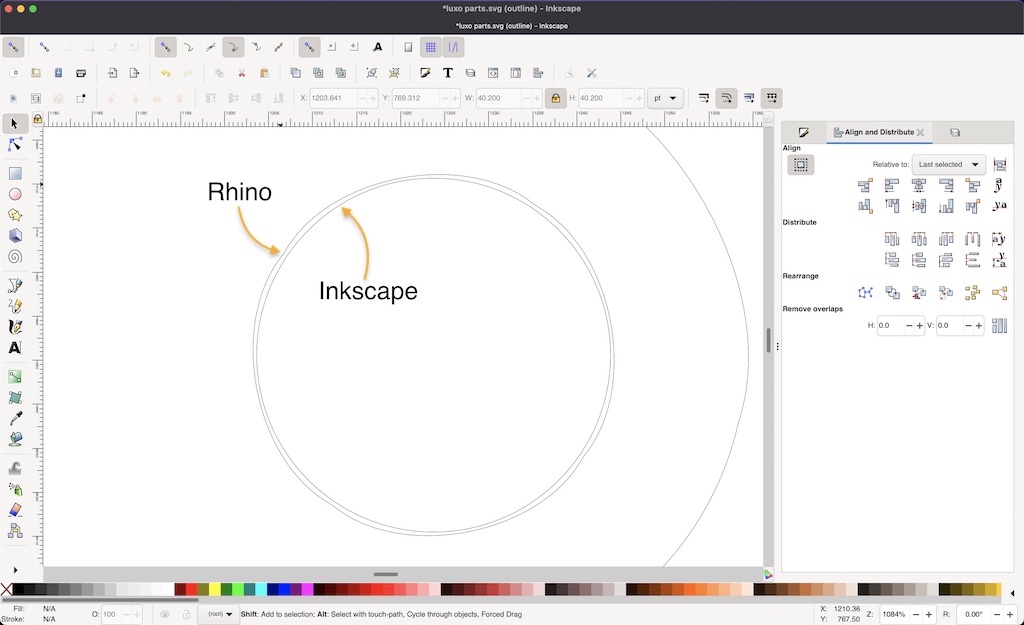
I then realised that some vectors looked odd. Circles weren’t perfect and I had to draw new ones in their place. In order to make sure the new circles were exactly concentric to the old ones, I used the Align and Distribute tool.
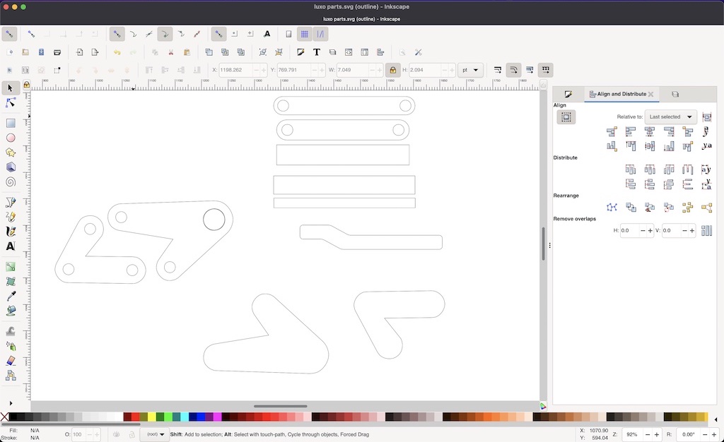
I ended up redrawing new shapes, as I wanted them to be rounder at the edges, yet keeping the hole locations at the exact point where they would work for my final model. It did take me a couple of iterations to nail the circle size to fit the aluminium rods I had.
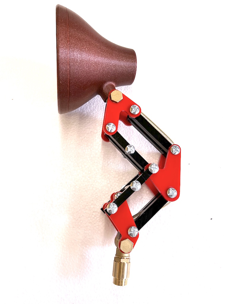
And the result, partially assembled
Animation
For 2024, my intructor Adrián Torres asked me to complement this week’s documentations with an animation of my model, “something simple”. It’s been over 20 years since my computer animation studies, so it took me a while to get back into it. I ended up loading my 3d model in Blender, and creating a physics animation. My objective was for the pieces of the model to fall to the ground, but it ended up exploding a bit. I find it to be a fitting visual metaphor for my profess in Fab Academy lately.
This is the final result, after some texturing, lighting and rendering.
Files
- Final Rhino 7 3d model of the head, in 3DM, zip compressed.
- As per requirements of open filetypes, a zip compressed STEP file has been added as well.
- Intermediate Fusion 360 threaded neck piece, in STEP, zip compressed
- Inkscape Work in progress file.
Checklist
Assignment
- Model (raster, vector, 2D, 3D, render, animate, simulate, …) a possible final project, compress your images and videos, and post it on your class page
Learning outcomes
- Evaluate and select 2D and 3D software
- Demonstrate and describe processes used in modelling with 2D and 3D software
Have you
- Modelled experimental objects/part of a possible project in 2D and 3D software
- Shown how you did it with words/images/screenshots
- Included your original design files