Input devices
Group Assignment
Reading a digital input device with an Oscilloscope
In 2024, my instructor Andrián emphatically suggested that I complete my documentation by reading an analog and a digital sensor with an oscilloscope.
I did have a cheap JVE Tech DSO Shell Kit, but I hadn’t put it together, so I contacted a Mechatronics professor at the university I work, to see if he could assist me in this task.
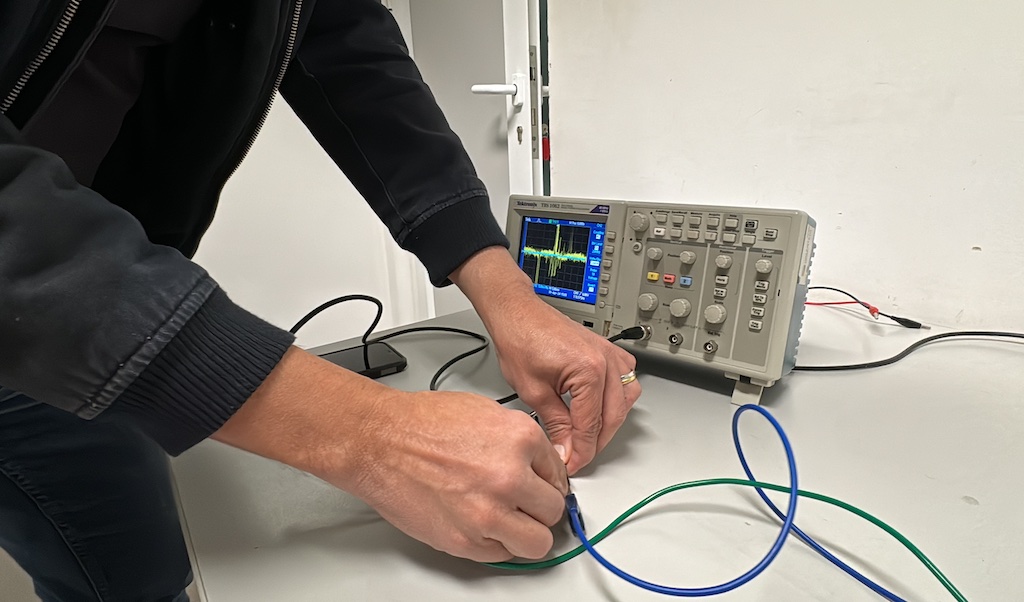
We met, and we tried out measuring a potentiometer, which, as he explained, was a silly task, as you only need a multimeter to read it. We also tried an ultrasonic distance sensor, but without a signal generator for the trigger, the echo wasn’t triggered and we only got noise in the oscilloscope, when connecting echo and trigger to it’s two channels.
 I hadn’t prepared properly, and the professor’s time naturally ran out.
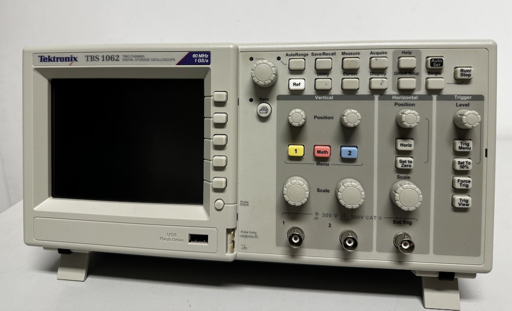
Yet, it was interesting to meet the professor and learn about their oscilloscope, the Tektronix TBS 1062, a benchtop digital storage oscilloscope with a maximum bandwidth of 60 MHz and features 2 analog channels.
I then decided to put my oscilloscope together and use that. The JYE Tech DSO Shell (DSO150) is a budget-friendly digital oscilloscope designed for hobbyists and educational purposes. Key specifications are:
- Number of Channels: 1
- Analog Bandwidth: 0 - 200 kHz
- Sensitivity: 5 mV/Div - 20 V/Div
- Resolution: 12-bit
- Input Impedance: 1 MΩ
- Maximum Input Voltage: 50V peak (using x1 probe)
- Coupling: DC, AC, GND
- Maximum Real-time Sampling Rate: 1 MS/s
- Timebase Range: 10 µs/Div - 500 s/Div
- Record Length: 1024 samples
- Trigger Modes: Auto, Normal, Single
- Trigger Types: Rising and falling edge
- Display: 2.4-inch color TFT LCD with 320 x 240 resolution
- Power Supply: 9V DC (8 - 10V acceptable), 120 mA at 9V
- Dimensions: 115 mm x 75 mm x 22 mm
- Weight: 100 grams (excluding cables and power supply)
With the help of ChatGPT, I got quite detailed instructions on how to measure my particular sensor, the HC-SR04 ultrasonic distance sensor, with my particular Oscilloscope. I got to ask the silly questions, which it answered kindly.
So, it suggested that I needed a micro-controller or signal generator to generate the trigger pulse, as well as the oscilloscope, of course, and a way to connect them. I used my Fab-Xiao board with a Seeeduino Xiao, a SAMD21 based board. ChatGPT suggested the code as well:
const int trigPin = 9; // Trigger pin connected to digital pin 9
const int echoPin = 10; // I left this in the code but connected this pin from the sensor directly to the oscilloscope

void setup() {
  pinMode(trigPin, OUTPUT);
  pinMode(echoPin, INPUT);
  digitalWrite(trigPin, LOW);
  delayMicroseconds(2);
}

void loop() {
  // Send a 10µs pulse to the Trigger pin
  digitalWrite(trigPin, HIGH);
  delayMicroseconds(10);
  digitalWrite(trigPin, LOW);

  // Wait for a short period before next measurement
  delay(100);
}
I copied it to the Arduino IDE, and after setting up the Seeed Xiao Board, I checked for compile errors. As Neil says, AI is almost always almost right. There were no errors, surprisingly, so I uploaded the code.
I then unplugged the Xiao, in order to safely establish the connections with dupont cables, as follows:
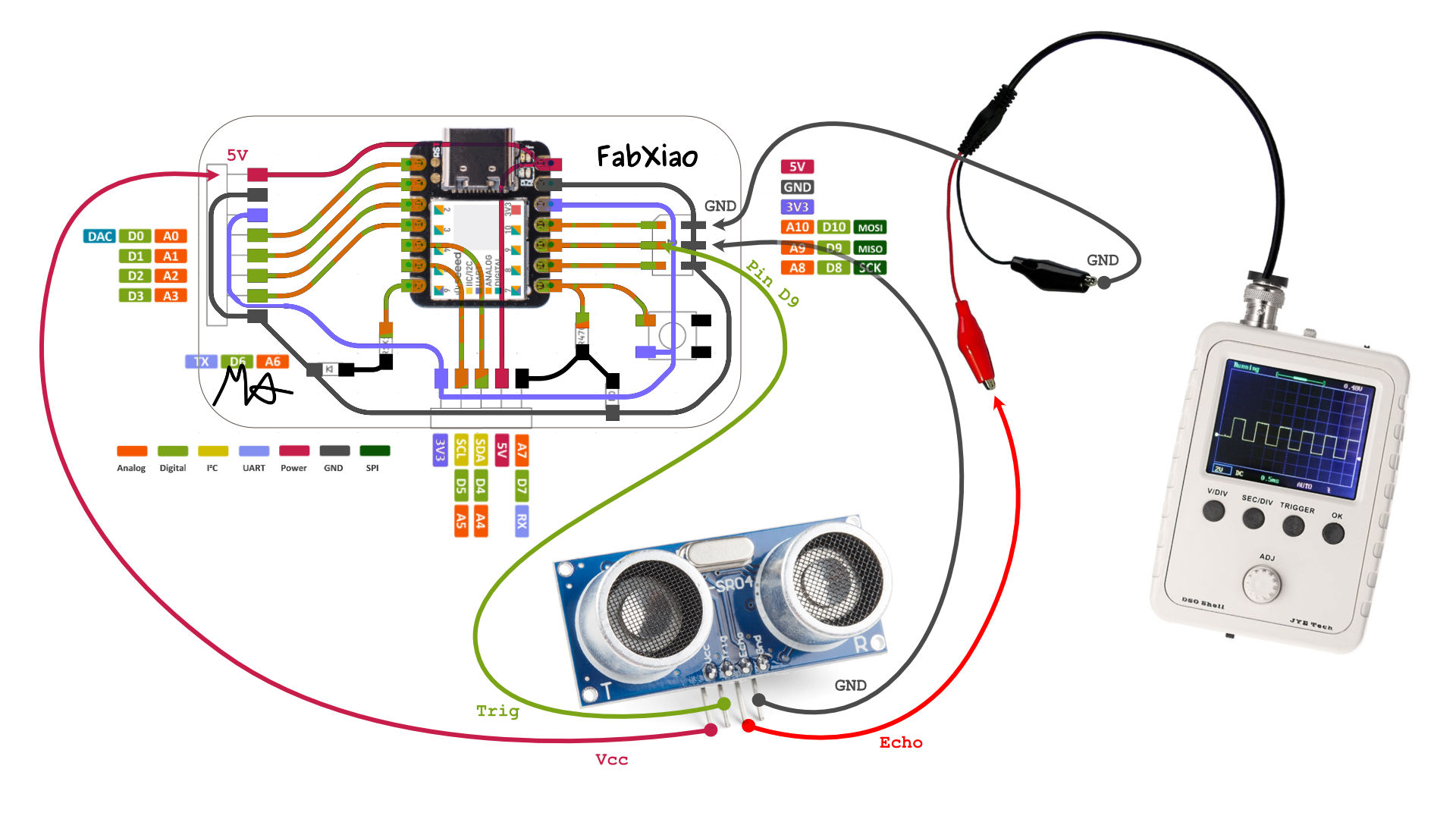
- Sensor VCC -> 5V
- Sensor Gnd -> Fab-Xiao Gnd
- Sensor Trigger -> Fab-Xiao Pin D9
- Sensor Echo -> Oscilloscope Signal alligator clamp
- Oscilloscope Gnd -> Fab-Xiao Gnd
I then plugged the oscilloscope to its 9V power supply and the Xiao to the computer. I observed the oscilloscope start operating and showing a square wave. I set the oscilloscope to a 2ms time base to capture the pulse width accurately, and set the voltage scale to capture the 5V signal. I could observe the wave became shorter in width as I moved my hand towards the ultrasonic sensor, and wider as I moved it away.
ChatGPT mentioned that one can use the pulse width to calculate the distance to the object, using the following formula, where value of 0.034 cm/µs is derived from the speed of sound in air. It’s apparently a commonly used approximation for converting the time it takes for an ultrasonic pulse to travel to an object and back into a distance measurement.
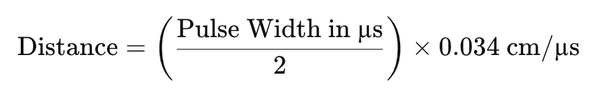
I haven’t figured out how to measure the pulse width on my oscilloscope, so I’ll have to leave that for another time.
Reading an analog input device with an Oscilloscope
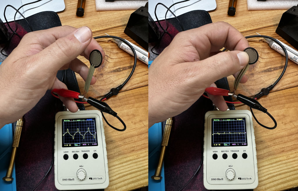
For the analog part of the assignment I was a little hindered by a lack of analog input devices. I found a force sensitive resistor and decided to measure that.
"At their core, Force Sensing Resistors are devices that produce a decrease in electrical resistance as more physical force or pressure is applied to them—putting them in the broader category of piezoresistive devices."
I simply connected the resistors terminals to signal and ground of the oscilloscope, and as I pressed the resistor, I could observe the graph move from a weird shaped curve to flatter line.
I also did the same with a potentiometer, even knowing it was a silly exercise.
I connected the wiper terminal so signal, and one of the other two terminals to ground. I then moved the knob to see the graph change.
Using an oscilloscope to test and measure FSRs and potentiometers provides a comprehensive view of their performance and behavior. It helps in verifying their response, identifying issues, and ensuring they meet the specific requirements of the application. This process is crucial in both development and troubleshooting stages, offering critical insights that enhance the reliability and functionality of electronic projects.
Individual Assignment
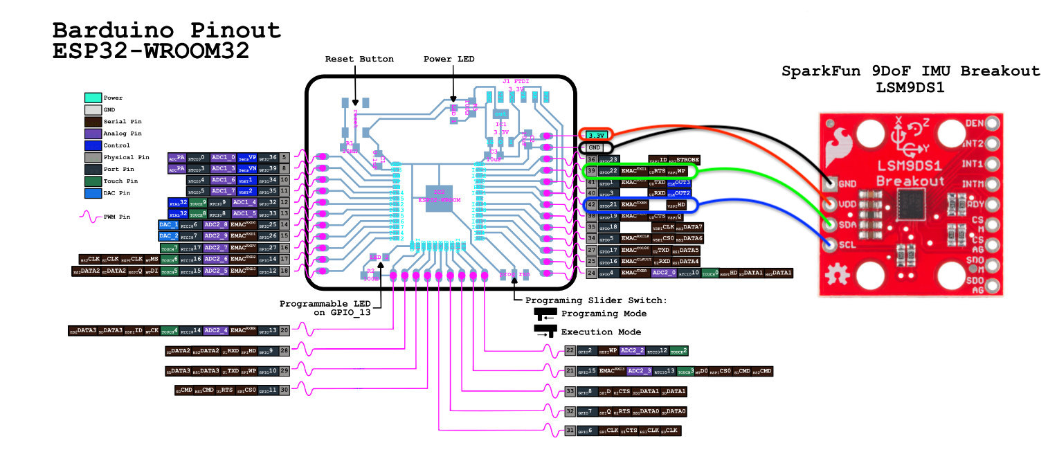
For this week, I experimented with a Sparkfun Breakout board that has a 3 axis Accelerometer, Gyroscope and Magnetometer, the lsm9ds1.
I don’t have access to other components, but did have this sensor board from an old kit I bought years ago.
The lsm9ds1 uses I2C communication, so I soldered its I2C pins and connected it to my Barduino as shown in the schematic.
I then installed Sparkfun’s Arduino Library for this breakout board, and opened an example sketch that makes use of all the sensors.
I uploaded the sketch to my Barduino and verified the functionality of the sensors by opening Arduino IDEs Serial Plotter.
In the video, a graphic is visible; it changes over time as sensor values are gathered and plotted. I moved the sensor, triggering the gyroscope in its axes, and also triggered the Magnetometer with my watch and a servo motor.
Files
Ultrasonic Sensor Oscilloscope testing sketch Example sketch for the lsm9ds1 Breakout Board
Checklist
Individual assignment
- Measure something: add a sensor to a micro-controller board that you have designed and read it.
Learning outcomes
- Demonstrate workflows used in sensing something with input device(s) and MCU board
Have you?
- Linked to the group assignment page
- Documented what you learned from interfacing an input device(s) to micro-controller and how the physical property relates to the measured results
- Documented your design and fabrication process or linked to previous examples.
- Explained the programming process/es you used
- Explained problems and how you fixed them
- Included original design files and source code
- Included a ‘hero shot/video’ of your board