Output devices
Group Assignment
For this week’s Group Assignment, please refer to this page
Individual Assignment
ESP32 first steps
ESP32 is a 32bit system on a chip that integrates Wi-Fi, Bluetooth, Dual cores, Low Power co-processor, and Multiple peripherals.
My final project will be ESP32 based, so I decided to do the next weeks’ exercises using the espressif ESP32-WROOM-32 devkit board I have at my disposal. I intended to explore this MCU to output directly from its embedded 8 bit DAC to a speaker and observe behavior and listen to the resulting sound, and try to measure the consumption of the circuit.
I followed Espressif’s instructions on getting started with the software environment, namely to install the prerequisites on my OSX machine, git clone the ESP-IDF, setup the tools, such as the compiler, debugger, Python packages, etc., to be able to flash programs into the MCU dev board.
I followed the instructions to a T, but each time I tried to flash a premade hello_world program I always got a frustrating error.

Since I had issues with python and trying to install Flatcam on my mac on week 4 - Electronics production, unsuccessfully, I was suspicious of my system, so I reverted to a relatively fresh Ubuntu Linux machine I have access to at home. I repeated all the steps, just to get the exact same error at the end of the process. Frustration had been a constant during my progres.
On a desperate last try, I installed the latest version of OSX, Catalina, on a new partition on my mac. Fresh start. After repeating all the steps again, I got the same error. Now I could definitely rule out computer software issues, but I still couldn’t get past the basics.
After much frustration and searching, I finally stumbled across a youtube video which specifically described the issue I was having and how to solve it: press the boot button when flashing the program until it starts uploading. I tried it and voilá! finally. Aparently the board I have would need a 0.1uF capacitor between EN and GND for it to accept flashing without pressing the boot button, but I’m just happy to press it for now.
Fashing the esp32 with the command
idf.py flash

Monitoring serial output with the command
idf.py monitor

Next I opened an example program in Visual Studio Code, where I decided to inspect the a2dp_sink example.
Explample a2dp_sink program from Espressif
// Copyright 2015-2016 Espressif Systems (Shanghai) PTE LTD
//
// Licensed under the Apache License, Version 2.0 (the "License");
// you may not use this file except in compliance with the License.
// You may obtain a copy of the License at

//     http://www.apache.org/licenses/LICENSE-2.0
//
// Unless required by applicable law or agreed to in writing, software
// distributed under the License is distributed on an "AS IS" BASIS,
// WITHOUT WARRANTIES OR CONDITIONS OF ANY KIND, either express or implied.
// See the License for the specific language governing permissions and
// limitations under the License.

#include <stdio.h>
#include <stdlib.h>
#include <unistd.h>
#include <string.h>
#include "freertos/FreeRTOS.h"
#include "freertos/task.h"
#include "nvs.h"
#include "nvs_flash.h"
#include "esp_system.h"
#include "esp_log.h"

#include "esp_bt.h"
#include "bt_app_core.h"
#include "bt_app_av.h"
#include "esp_bt_main.h"
#include "esp_bt_device.h"
#include "esp_gap_bt_api.h"
#include "esp_a2dp_api.h"
#include "esp_avrc_api.h"
#include "driver/i2s.h"

/* event for handler "bt_av_hdl_stack_up */
enum {
    BT_APP_EVT_STACK_UP = 0,
};

/* handler for bluetooth stack enabled events */
static void bt_av_hdl_stack_evt(uint16_t event, void *p_param);


void app_main()
{
    /* Initialize NVS — it is used to store PHY calibration data */
    esp_err_t err = nvs_flash_init();
    if (err == ESP_ERR_NVS_NO_FREE_PAGES || err == ESP_ERR_NVS_NEW_VERSION_FOUND) {
        ESP_ERROR_CHECK(nvs_flash_erase());
        err = nvs_flash_init();
    }
    ESP_ERROR_CHECK(err);

    i2s_config_t i2s_config = {
#ifdef CONFIG_EXAMPLE_A2DP_SINK_OUTPUT_INTERNAL_DAC
        .mode = I2S_MODE_MASTER | I2S_MODE_TX | I2S_MODE_DAC_BUILT_IN,
#else
        .mode = I2S_MODE_MASTER | I2S_MODE_TX,                                  // Only TX
#endif
        .sample_rate = 44100,
        .bits_per_sample = 16,
        .channel_format = I2S_CHANNEL_FMT_RIGHT_LEFT,                           //2-channels
        .communication_format = I2S_COMM_FORMAT_I2S_MSB,
        .dma_buf_count = 6,
        .dma_buf_len = 60,
        .intr_alloc_flags = 0,                                                  //Default interrupt priority
        .tx_desc_auto_clear = true                                              //Auto clear tx descriptor on underflow
    };


    i2s_driver_install(0, &i2s_config, 0, NULL);
#ifdef CONFIG_EXAMPLE_A2DP_SINK_OUTPUT_INTERNAL_DAC
    i2s_set_dac_mode(I2S_DAC_CHANNEL_BOTH_EN);
    i2s_set_pin(0, NULL);
#else
    i2s_pin_config_t pin_config = {
        .bck_io_num = CONFIG_EXAMPLE_I2S_BCK_PIN,
        .ws_io_num = CONFIG_EXAMPLE_I2S_LRCK_PIN,
        .data_out_num = CONFIG_EXAMPLE_I2S_DATA_PIN,
        .data_in_num = -1                                                       //Not used
    };

    i2s_set_pin(0, &pin_config);
#endif


    ESP_ERROR_CHECK(esp_bt_controller_mem_release(ESP_BT_MODE_BLE));

    esp_bt_controller_config_t bt_cfg = BT_CONTROLLER_INIT_CONFIG_DEFAULT();
    if ((err = esp_bt_controller_init(&bt_cfg)) != ESP_OK) {
        ESP_LOGE(BT_AV_TAG, "%s initialize controller failed: %s\n", __func__, esp_err_to_name(err));
        return;
    }

    if ((err = esp_bt_controller_enable(ESP_BT_MODE_CLASSIC_BT)) != ESP_OK) {
        ESP_LOGE(BT_AV_TAG, "%s enable controller failed: %s\n", __func__, esp_err_to_name(err));
        return;
    }

    if ((err = esp_bluedroid_init()) != ESP_OK) {
        ESP_LOGE(BT_AV_TAG, "%s initialize bluedroid failed: %s\n", __func__, esp_err_to_name(err));
        return;
    }

    if ((err = esp_bluedroid_enable()) != ESP_OK) {
        ESP_LOGE(BT_AV_TAG, "%s enable bluedroid failed: %s\n", __func__, esp_err_to_name(err));
        return;
    }

    /* create application task */
    bt_app_task_start_up();

    /* Bluetooth device name, connection mode and profile set up */
    bt_app_work_dispatch(bt_av_hdl_stack_evt, BT_APP_EVT_STACK_UP, NULL, 0, NULL);

#if (CONFIG_BT_SSP_ENABLED == true)
    /* Set default parameters for Secure Simple Pairing */
    esp_bt_sp_param_t param_type = ESP_BT_SP_IOCAP_MODE;
    esp_bt_io_cap_t iocap = ESP_BT_IO_CAP_IO;
    esp_bt_gap_set_security_param(param_type, &iocap, sizeof(uint8_t));
#endif

    /*
     * Set default parameters for Legacy Pairing
     * Use fixed pin code
     */
    esp_bt_pin_type_t pin_type = ESP_BT_PIN_TYPE_FIXED;
    esp_bt_pin_code_t pin_code;
    pin_code[0] = '1';
    pin_code[1] = '2';
    pin_code[2] = '3';
    pin_code[3] = '4';
    esp_bt_gap_set_pin(pin_type, 4, pin_code);

}

void bt_app_gap_cb(esp_bt_gap_cb_event_t event, esp_bt_gap_cb_param_t *param)
{
    switch (event) {
    case ESP_BT_GAP_AUTH_CMPL_EVT: {
        if (param->auth_cmpl.stat == ESP_BT_STATUS_SUCCESS) {
            ESP_LOGI(BT_AV_TAG, "authentication success: %s", param->auth_cmpl.device_name);
            esp_log_buffer_hex(BT_AV_TAG, param->auth_cmpl.bda, ESP_BD_ADDR_LEN);
        } else {
            ESP_LOGE(BT_AV_TAG, "authentication failed, status:%d", param->auth_cmpl.stat);
        }
        break;
    }

#if (CONFIG_BT_SSP_ENABLED == true)
    case ESP_BT_GAP_CFM_REQ_EVT:
        ESP_LOGI(BT_AV_TAG, "ESP_BT_GAP_CFM_REQ_EVT Please compare the numeric value: %d", param->cfm_req.num_val);
        esp_bt_gap_ssp_confirm_reply(param->cfm_req.bda, true);
        break;
    case ESP_BT_GAP_KEY_NOTIF_EVT:
        ESP_LOGI(BT_AV_TAG, "ESP_BT_GAP_KEY_NOTIF_EVT passkey:%d", param->key_notif.passkey);
        break;
    case ESP_BT_GAP_KEY_REQ_EVT:
        ESP_LOGI(BT_AV_TAG, "ESP_BT_GAP_KEY_REQ_EVT Please enter passkey!");
        break;
#endif

    default: {
        ESP_LOGI(BT_AV_TAG, "event: %d", event);
        break;
    }
    }
    return;
}
static void bt_av_hdl_stack_evt(uint16_t event, void *p_param)
{
    ESP_LOGD(BT_AV_TAG, "%s evt %d", __func__, event);
    switch (event) {
    case BT_APP_EVT_STACK_UP: {
        /* set up device name */
        char *dev_name = "ESP_BESTIAL";
        esp_bt_dev_set_device_name(dev_name);

        esp_bt_gap_register_callback(bt_app_gap_cb);

        /* initialize AVRCP controller */
        esp_avrc_ct_init();
        esp_avrc_ct_register_callback(bt_app_rc_ct_cb);
        /* initialize AVRCP target */
        assert (esp_avrc_tg_init() == ESP_OK);
        esp_avrc_tg_register_callback(bt_app_rc_tg_cb);

        esp_avrc_rn_evt_cap_mask_t evt_set = {0};
        esp_avrc_rn_evt_bit_mask_operation(ESP_AVRC_BIT_MASK_OP_SET, &evt_set, ESP_AVRC_RN_VOLUME_CHANGE);
        assert(esp_avrc_tg_set_rn_evt_cap(&evt_set) == ESP_OK);

        /* initialize A2DP sink */
        esp_a2d_register_callback(&bt_app_a2d_cb);
        esp_a2d_sink_register_data_callback(bt_app_a2d_data_cb);
        esp_a2d_sink_init();

        /* set discoverable and connectable mode, wait to be connected */
        esp_bt_gap_set_scan_mode(ESP_BT_CONNECTABLE, ESP_BT_GENERAL_DISCOVERABLE);
        break;
    }
    default:
        ESP_LOGE(BT_AV_TAG, "%s unhandled evt %d", __func__, event);
        break;
    }
}
So this code is far too complex for me to really understand what’s going on yet, as I know little of programming, but I did change one line so I could track if the code was what I had edited:
char *dev_name = "ESP_SPEAKER";
to
char *dev_name = "ESP_BESTIAL";
This names the bluetooth device and is visible when pairing to the ESP.
I then built the code by following these steps in terminal:
cd ~/esp/esp-idf/examples/bluetooth/bluedroid/classic_bt/a2dp_sink

. $HOME/esp/esp-idf/export.sh

idf.py build
Then finally flashed the compiled program to the ESP32 Dev Board while pressing the boot button
idf.py flash
I then connected a speaker to the ESP’s ground and pin D25, one of the ESP’s DAC’s output pins, started serial monitor
idf.py monitor
Paired the ESP via bluetooth to my computer and started getting audio output on the speaker. There is a terrible noise distortion coming out of it but it is also noticeable that the sound is coming from the computer.
ESP32 Barduino
For this week I was met with a conundrum. I had limited access to electronics components, so I decided to make a general purpose board which would allow me to test inputs, outputs and application programming, instead of making one board for each of those weeks. I was undecided between Adrian Torres’ Adrianino, Quentin Bolsee’s SAMD11C dev kit board or also his SAMD21 dev kit board. I wanted a design that offered as many pins as possible for one of these processors, as I have a couple of them at hand. All these boards are amazing designs, fababble in a one layer PCB and great candidates for this task.


Adrian warned me in Global Open Time that SAMDs work with 3.3V, which would be limiting for the more standard 5V used by sensors and output devices, which Adrianino’s ATtiny1614 or ATtiny1624 support. Considering I was probably going to power my board over USB, for simplicity, I thought I could use a regulator to feed the processor with 3.3V and keep a 5V line for those peripherals that need it, protecting processor pins that receive signals from those sensors with a resistor. Quentin confirmed my theory in fabacademy’s mattermost, so I felt confident about that.
Nevertheless, looking ahead to my final project, which will need WiFi and Bluetooth, it would make sense to pivot my efforts to the processor I was planning to use, the ESP32. I had made some experiments with a dev board in 2020, as can be seen above, but hadn’t made my own. I searched for a fababble ESP32 board, and came across Barduino 2.0, developed by Eduardo Chamorro Martin with the help of Josep Marti and Oscar Gonzalez, in Fab Lab Barcelona a few years back. It is also a fababble one-sided pcb design, so I was interested.

There are 3 versions of this board on the repository: one that is FTDI programmable, and two that use micro-USB and integrate the FTDI chip onboard.
I have an FTDI-USB cable, the 3.3V variant (there is also a 5V FTDI cable, but I don’t have that), so programming the simpler board would be facilitated. Unfortunately though, I’d be stuck with only 3.3V, which I thought was important.

I decided to clone the repo and start customizing Barduino 2.2 in KiCad. I wanted to substitute the micro-USB plug design with a CONN_USB_A design, just like in my previous boards, because I knew I didn’t have a micro usb plug, and the USB A (full size) plug is machinable on the copper plates with the cnc, so it seemed the way to go for me.
I copied the CONN_USB_A symbol from my SAMD11C programmer Kicad and pasted it onto the Barduino schematic, replacing the micro usb symbol and reconnecting the vias. ERC didn’t complain about it, so I went on to the board design and that’s when I noticed it wasn’t going to be so easy.

To my luck, the connectors don’t seem to be simply interchangeable, so there were crossed links in the rats nest, and it would have had to be completely redrawn.

USB Plugs
USB connectors come in a variety of orientation and mounting styles. This dictates how USB connectors are placed and secured on a PCB. There are three key mount types: Surface mount, Through hole and Hybrid (a mixture of the two). There are also three key mount positions; Top, Mid and Bottom. Finally there is the Mount orientation which can either be horizontal or vertical. Pinout does not necessarily match between connector types.

Simultaneously, I went to check if I had the FT230SX chip that was needed to make the board USB pluggable, and turns out that neither I or my instructor at FCT Fablab have them, and OctoPart only listed two vendors who had it, but only sold in large quantities, as far as I understood their sites.
Alright, nevermind, back to the simpler FTDI version of Barduino.
I opened the KiCad schematic for the FTDI version, checked I had all the components to populate the board and decided that if I’m copying that design, at least I’d make a little bit mine, by rounding the tracks, which is something I find makes the boards unusual and pretty.
In KiCad, there’s a plugin to make the tracks curved. I had installed it before and used it on my SAMD11C Hello Board. At the time I noticed some quirks about the plugin, namely that once you run it, it’s nearly impossible to make changes to the tracks, as they become several disjoint curves. I also noticed that, at least in my mac computer, undoing the plugin returned the tracks to their original form, enabling easier edits, but made KiCad crash. So the solution was to save the board design before running the curves plugin. One thing to keep attention to, is to check clearances, as the resulting curves tend to ignore the rules and sometimes come too close to component pads, or even touch them, which would be bad if left unnoticed.

After a few alterations to the original design, I was happy with the result, and exported the SVGs from KiCad. As usual, I opened them in Inkscape, separated relevant elements to their own layers and exported new PNGs for Front Copper and Board Edge Cut. In this case I included pin holes for the connector headers I’d solder in.


Milling the Board
I then proceeded to Mods Community Edition and prepared the files for machining.
I opened the Roland MDX PCB server program, because I was going to try milling on the Roland MDX-50 that we have at _ARTERIA_LAB, where I work.

I had ordered new milling bits, and decided to use them to mill this very detailed ESP32 board. In fact, I don’t think I could have milled it without the 0.1mm V-bit, as the traces between the processor pads are so small.
I was also very thankful for the new (to me) V-bit calculator in Mods. I had found it in the SRM-20 Mill > PCB CE experimental program, which I had opened by curiosity. The Roland MDX PCB doesn’t have that module by default yet, but I added the module from the list and connected it to the settings in the Mill Raster 2d Module, like I saw in the SRM-20 program.
I imported my Front Copper traces PNG and immediately inverted it. Mods calculates the paths in the black part, so if you don’t invert the image, it’ll mill the inside of the traces as opposed to the outside, and that’s no bueno. Ask me how I know this.

I set the tool diameter to 0.1mm, the angle to 30º, and very importantly, the depth I wanted to cut the board to 0.1016mm, the default in the mill raster 2d module. I figured if it’s there by default, it’s because Neil put it there, and after a lot of trial and error in previous weeks with mods, I trust Neil XD The depth value is what is used to calculate the final cut width, and that’s what allows Mill Raster 2D to calculate accurate paths that will actually work with my V-bit.
After that, I made sure to set the model to MDX-40, which is compatible with out MDX-50, I left Cut Speed at a fairly conservative 2.5mm/s (I could always speed it up or slow it down on the MDX-50’s menu during the operation) and lowered the Jog Z to 1 mm. Jog Z is the height the mill raises to when moving from one part of the board to another, while not milling. The higher you go, the more time is spent in the move, so lower is faster, if it’s safe. Check your setup, or you could crash a mill bit.

The last thing in Mods is to save the .rml file instead of sending it directly to the Roland. I’m not controlling the MDX-50 directly with Mods yet, so I have to send the file to the mill through V-Panel, the dedicated software that controls the MDX-50 in Windows.
In the MDX-50, I load the bit I want to use, move X, Y and Z to the lower left corner of the FR2 copper board and set the origin for all 3 axes in the user coordinate system. I then open V-Panel in windows, load the RML file, breath in and … press send. The machine starts moving, and if you’re lucky, your 4th attempt will come out just like this, in the last remaining area of the copper blank.

Failed attempts
Yeah, the picture above is of my 4th attempt. It isn’t always easy like I described above. In fact, It’s almost never easy for me, hardly ever on the first attempt. On my first attempt I was using a 0.2mm V-bit and didn’t even realize Mods hadn’t been able to calculate the paths between the ESP32’s pads, until I had even cleared the whole board. There were also lots of burrs on the tracks, some broken ones for a reason I haven’t even discerned yet, and a connected track to the FTDI RTS pin. It was late at work so I decided to try at home.

On my second attempt, I decided to mill the board on my Genmitsu 3018 cnc at home, like described in Electronics Production Week. It was going well until the PC I was using lost USB connection for a reason I’m yet to discover, and the Genmitsu simply stopped. That meant I had lost the Zeros on the axes and couldn’t even recover the job. Frustration made me give up that night and start again on the MDX-50 the next day. I didn’t even take a picture of that.
On my third attempt I inverted the PNG on the edge cut and holes pass, and this happened:

I wish I could say that this is how I found out about inverting the PNGs in Mods, but it’d happened before, I should have paid attention properly. I inverted the PNG but didn’t pay attention to the fact that it didn’t need to be inverted. I had designed it right in Inkscape. Moral of this story is, always try to pay attention before commiting to your next attempt.
And now, on with the process of making the board properly, as if failures hadn’t happened.
Once the outline with the fine v-bit was successful, I went back to Mods and, using the same Front Copper PNG file, I changed the mill bit to a considerably fatter 0,8mm tool, and the offset number to 0, in order to fill all the remaining black space with milling traces. The rationale for this is that the board needs to have a copper free area for the ESP32’s Wifi and Bluetooth antenna. The emotionale to this is that I like the way the board looks when it’s totally clear of copper except for the curved traces and pads. So, there you go.

I changed the mill on the MDX-50, took extra care to keep X and Y origins, and set the fat mills Z Zero on the copper’s top. Open the new .rml file in V-Panel and breathe in before pressing send.

That turned out alright, I was happy with it. A few islands to clear, but mostly quite nice for my standards. But there was one last pass before I could celebrate. Back to Mods, open the Edge Cut and holes PNG, set the parameters for Mill Outline, triple check that the paths make sense and aren’t too large, measure the board thickness with a Vernier Caliper so you know you’re not milling too deep or too shallow, and generate the next file.
Open V-Panel, load the new file, quadruple check the origins on the machine, breath in… and press send.

Well, that turned out reeal fine :D


Components seemed to fit perfectly.
Populating the Board
I knew the ESP32 had some ground pins right in its belly, as the board shows, and I had been thinking about how to solder those. I do have a hot air station, but was afraid to heat the board from the underside too much. I don’t have a hot plate, but I tried using an old clothes iron to desolder components from a failed board, so I decided to try that, like it was any safer than the hot air. Well, at least the processor would stay in it’s place if I was careful to keep the iron horizontal. With the hot air gun it seemed like it would be an uncomfortable balancing act.

I laid some solder paste in the pads of the board and carefully aligned the ESP in its place. I then secured the iron in a vise and turned it on, laying the board on the hot surface. At first it didn’t seem like it was going to work, but suddenly I saw the paste on the pins turn silver, and a little puff of smoke let me know it may have been too much heat already, so I quickly removed the board with tweezers. As it cooled, it seemed like the processor was stuck in the right place. Careful inspection with the magnifying glass seemed to suggest most pins were connected and the ESP32 was level with the board.


I then used a multimeter to check the pins and sure enough, a few were not beeping, but most were connected. I then decided to reinforce all connections with normal solder and the fine tipped iron. Once that was done (it took a fair while, because I was being extra careful) I rechecked all connections were beeping with the multimeter. I then started soldering all the other components. I found that solder paste works remarcably well with the fine tipped iron, as I can apply heat in a very controlled area, instead of a larger area when using the hot air reflow station. It’s also easier to place the smd components on the paste and hold them in their best position with tweezers as I apply heat with the iron. Anyway, it seemed to work fine.


A little bit of clean up with isopropyl alcohol to do, and it’s good. Not the best solder job I’ve ever seen, but it’s probably my best.
Programming the first Output
I had had experience with Expressif IDF a couple of years ago, enough to know it’s not as easy as with the Arduino IDE. I’m still learning how to program simple things, investigating the sketches and trying to understand how they work. So, for now, I’ll follow some Arduino IDE examples and check if my Barduino works.
I had read here and here that I should install these board sources. I had previously installed Arduino IDE 2.0.0 Release Candidate 5 on my mac, and had noticed that adding new addresses on the Board Manager didn’t quite work. Pasting the addresses there did nothing. So I opened Arduino IDE 1.8.12 which I still have from previous endeavors, and tried again there. That worked, and once the older IDE had loaded the ESP32 boards, I opened the 2.0.0 version again, and since the two versions can co-exist and share preferences, the new boards showed up on the newer version too. Cool, I like the new version, despite some minor issues.
To connect the cable to the Barduino correctly, attention needs to be paid to its orientation, obviously. A quick search for the 3.3V FTDI cable pinout led me to this helpful image:

Knowing which pin is ground on the board is easy if you look at the board design, but I decided to remember that the little triangle goes down. Easier is betterer.
I’m thinking I’ll add a pinout cheat sheet to the bottom part of the board to help in the future, but for now I’ll link this here, from the original repository:
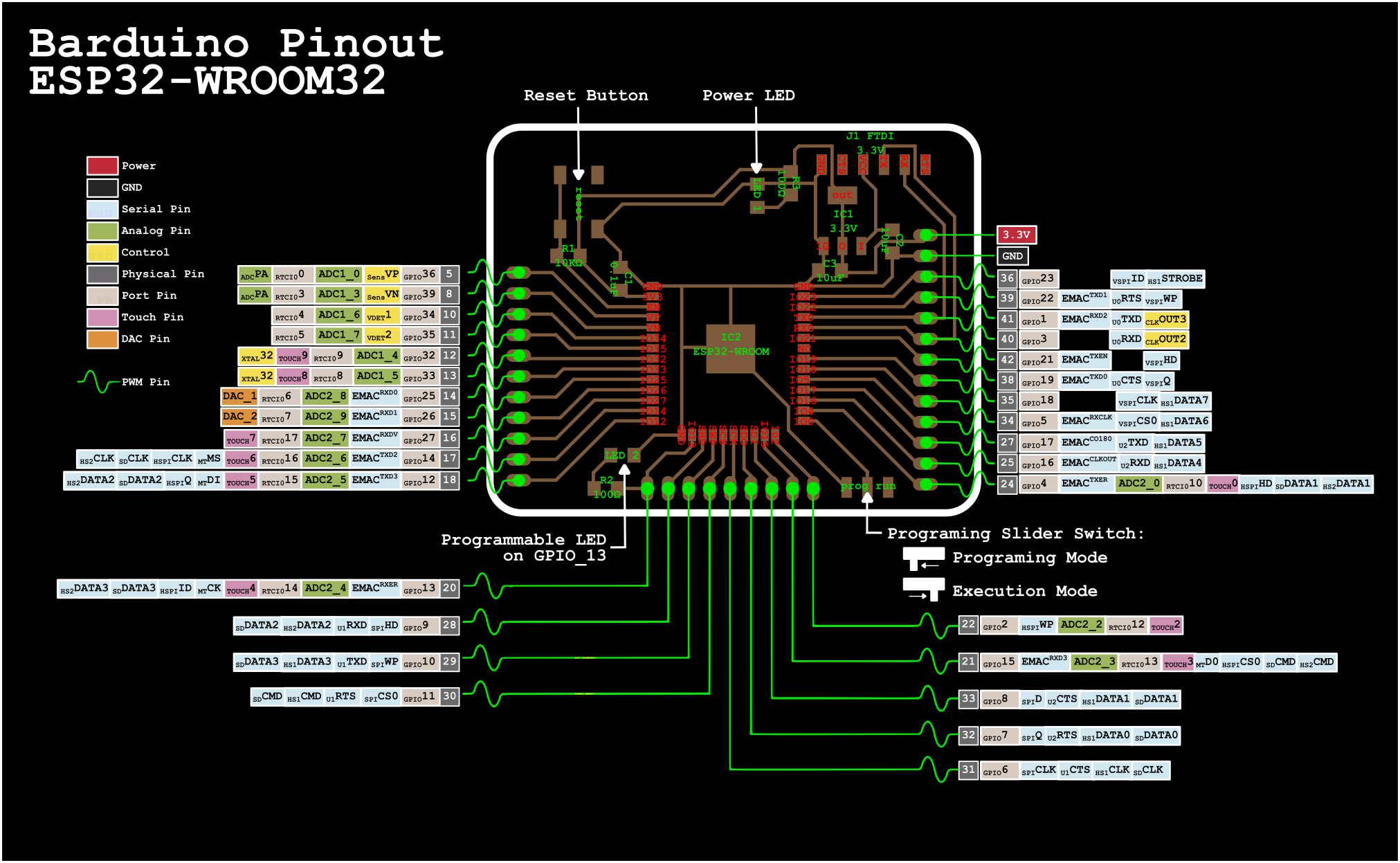
The Barduino has a nice LED designed at pin 13, so it was simple to try out a LED fade arduino example sketch.
- Load up the sketch from Examples > Basics > Fade**
- change int led = 9; to int led = 13;
- Connect my FTDI cable correctly to the Barduino and to the computer (the power LED will light up when connected to the computer)
- In Arduino IDE, select the right board under Tools > Board > ESP32 > ESP32 Dev Module**
- breathe in and… press upload
Alright! Sucesso!
OLED Output!
Next, I wanted to try connecting a small OLED screen I have. A bit of a search and a few tutorials and fellow fab students’ documentation later, I found out my screen is a Shenzhen clone of an Adafruit SSD1306, 128x32 pixels, 0.96”, I2C screen. I also learned I had to install these libraries in the Library Manager to make it work:
- Adafruit_GFX
- Adafruit_SSD1306
- Adafruit_BusIO
Once I had installed the libraries, new examples showed up in the list, so I selected the aptly named Adafruit_SSD1306_128x32_I2C. I had a little look at the code and checked that the SCREEN_ADDRESS was set to 0x3C, as one of the tutorials suggested. Once that was confirmed, I connected GND and VCC on both boards. The default I2C pins on the ESP32 are GPIO 22 (SCL) and GPIO 21 (SDA), according to this random nerd tutorial, so I connected those pins and proceeded as before, to verify and upload the example Sketch.

Yeah, worked alright! What a relief and great satisfaction, even though I didn’t really program anything yet, I’m super happy that my board works and that the potential is there for it to be my final project first iteration board.
Fixing compilation issue in OSX Monterrey
After updating Mac OSX to monterrey version, I stopped being able to compile for the ESP32. The issue is related to how OSX stopped supporting python, even though I had python3 installed via HomeBrew. After some searching, I came accross the solution, here, which involves substitution the variable ‘python’ in one of the ESP32 Library platform file, with the executables actual location on disk.
Files
Barduino Kicad Schematics
Marius’ Barduino board PNG file
Arduino example from Adafruit to test SSD1306 oled screen
Checklist
Group assignment
- Measure the power consumption of an output device
- Document your work (in a group or individually)
Individual assignment
- Add an output device to a microcontroller board you’ve designed and program it to do something
Learning outcomes
- Demonstrate workflows used in controlling an output device(s) with MCU board you have designed
Have you?
- Linked to the group assignment page
- Documented how you determined power consumption of an output device with your group
- Documented what you learned from interfacing output device(s) to microcontroller and controlling the device(s)
- Described your design and fabrication process or linked to previous examples.
- Explained the programming process/es you used
- Outlined problems and how you fixed them
- Included original design files and code
- Included a ‘hero shot/video’ of your board