Computer controlled cutting
This week is dedicated to Computer Controlled Cutting, with the specific tasks of characterizing our lasercutters focus, power, speed, rate, kerf, and joint clearance as group assignment. As individual assignment we were to cut something on the vinylcutter, and design, lasercut, and document a parametric construction kit, accounting for the lasercutter kerf, which can be assembled in multiple ways, and for extra credit include elements that aren’t flat.
Group Assignment
First thing was to determine the make and model of the Laser Cutter, an Epilog Mini. It’s a 40W CO2 tube laser, 610 X 305mm bed.
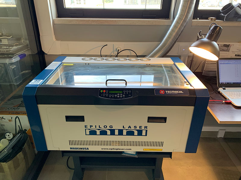
It has auto-focus, but generally that feature is deprecated in favor of a manual focus process, which seems to be more reliable in this particular machine. The laser cutter is controlled via a laptop using Corel Draw, where designs are aligned and prepared for “printing”. Once the vector or raster designs are ready, it’s via the printing preferences that we determine Power, Speed and Rate.
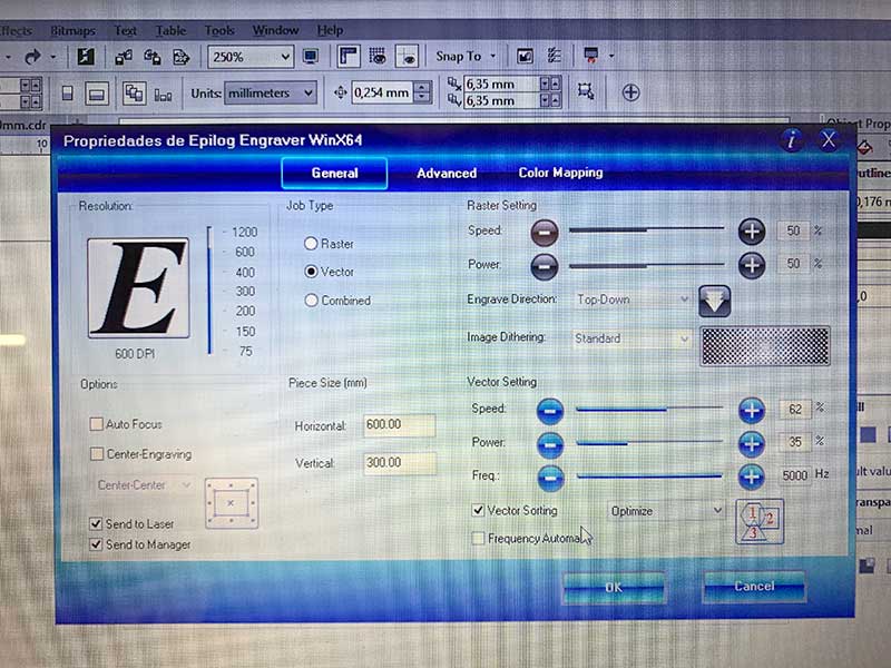
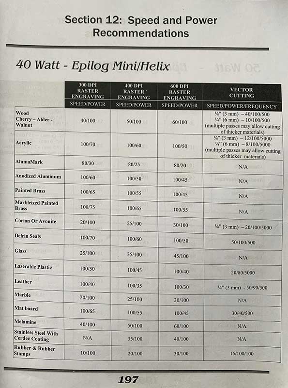
Power and Speed are selected as a percentage of unknown maximum values, ie., not in actual Watt or millimeters per second units. We can assume Power will be a percentage of the stated 40 watts, but no way of actually measuring it. Rate is determined as a unit value. A chart from the Epilog manual states reference values for several materials, such as woods and acrylics. A rate of 500 for most organic materials, and 5000 for most plastics and acrylics.
 |
|---|
| Reference Values |
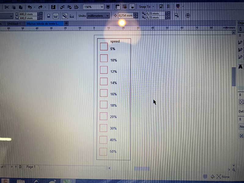
In order to measure the sweet spot of cutting speed and power, so as to actually go through the material but not leave and excessively charred edge, we created a design of 5mm hairline square shapes, which we then colored with different RBG values in corel draw.
 |
|---|
| Measuring Design |
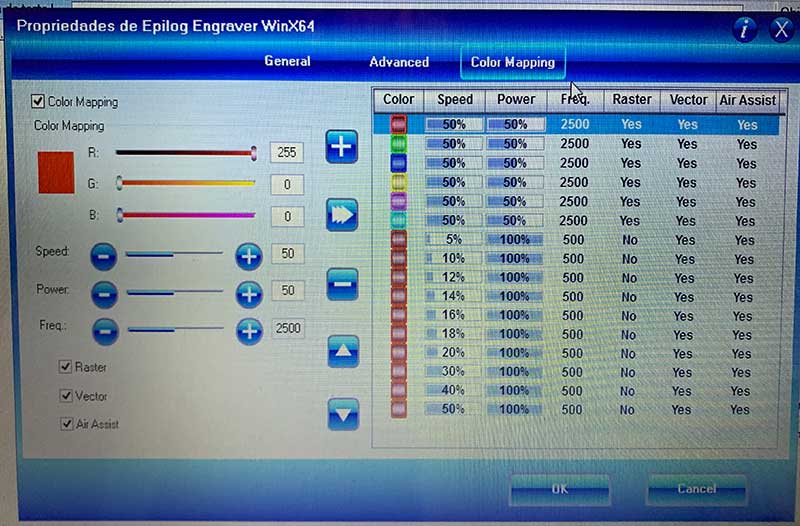
These rgb values were then assigned different speed values; power was kept at 100%, as recommended by out Fab Manager, who knows the machine very well.
It was also suggested that the sweet-spot would be between 10 and 30% speed at max power, so the test was prepared to 5%, 10%, then 12, 14, 16, 18, 20% and then 30, 40 and 50%.
 |
|---|
| Color coded cutting |
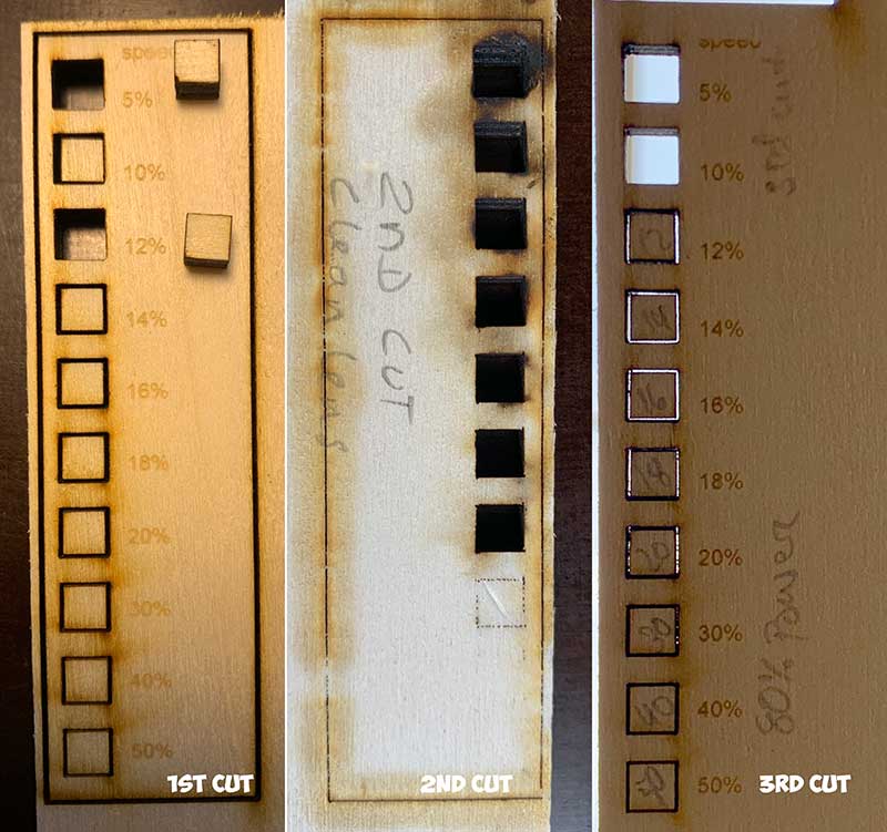
As predicted, 5 and 10% speed produced quite charred cuts, which became less so up to 20%; 30, 40 and 50% speeds were too fast and produced shallower cuts that didn’t go through the material.
3 test cuts were made: The 1st Cut was as described above, the 2nd Cut was the same settings except we cleaned the lens and mirror, which actually made a significant change in the speed at which 100% power cut through the material, at 20% speed rather than 12%. The 3rd cut demonstrated that at the same speeds but only 80% power, the laser would only produce a clean through cut at lower speeds of 18%, which makes sense.
 |
|---|
| Cut Tests |
As a way to measure Kerf, the width of material that the laser burns away as it cuts through the material, a Vernier Caliper was used to measure the width and length of the cut material, the inside dimensions of the hole left from the removed piece, and those values compared with the originally designed dimensions.
Values varied a little, but it was determined that Kerf was between 0.1 and 0.2mm, which would be confirmed later during the Parametric construction kit design and testing.
Parametric construction kit
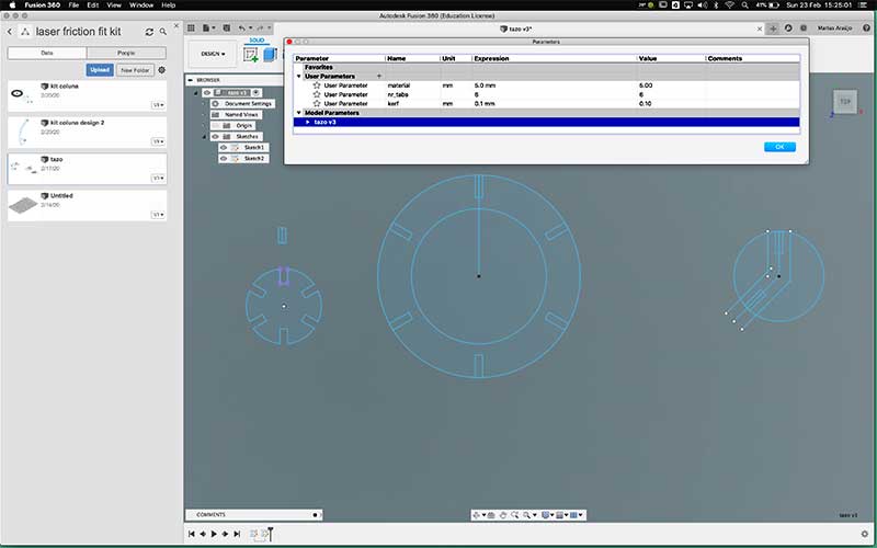
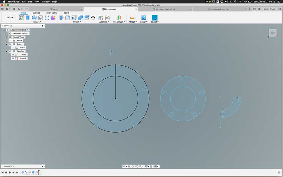
Next I turned to Fusion 360 to design the parametric construction kit.
I drew a cicle and a rectangle. The rectangle’s shorter side has a dimention of (material width - laser kerf), parameters I had predetermined. It was then copied around the edge of the circle with a polar array function. I then exported a dxf file
 |
|---|
| Parametric contruction kit. 5mm material width, 0.2mm kerf |
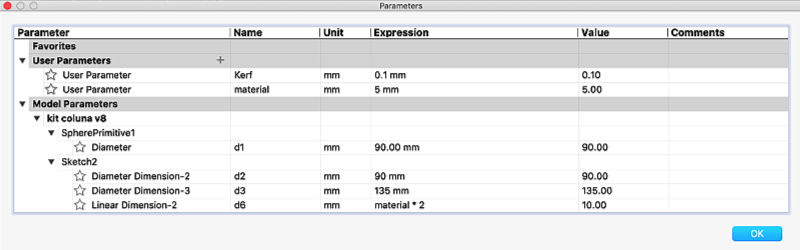
Custom parameters were defined for Material Width and Kerf. These were used to determine joint size.
| |
|:–:|
|Kit Parameters|
|
|:–:|
|Kit Parameters|
| Parameter | value |
|---|---|
| Material Width | 5.0mm |
| Laser Kerf | 0.2mm |
5mm MDF boards were the chosen material, because good cardboard doesn’t seem so easy to source here, and MDF was readily available. The width was measured at several points with the caliper rule and were fairly consistent, the average of which was determined to be at 5.02, a slight deviation from stated width.
Several test cuts were performed until a secure press-fit was achieved. For a secure fit, I determined that designing 4.8mm slots gave me the most friction to hold the pieces together firmly. This value was verified empirically, but derived from the width of the material minus the kerf of the laser.
 |
|---|
| Paressfit contruction pieces |
Better
I then proceeded to design a first draft of a puzzle that served both as a more practical experiment for the press fit kit, and also included flexible pieces, achieved through cutting small slots into the material, a technique known as kerf bending.
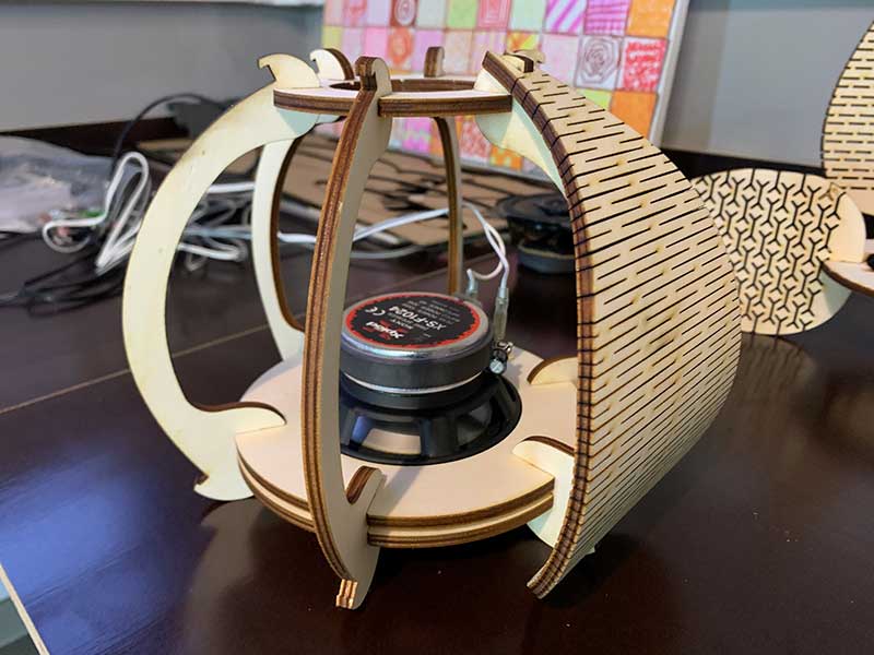
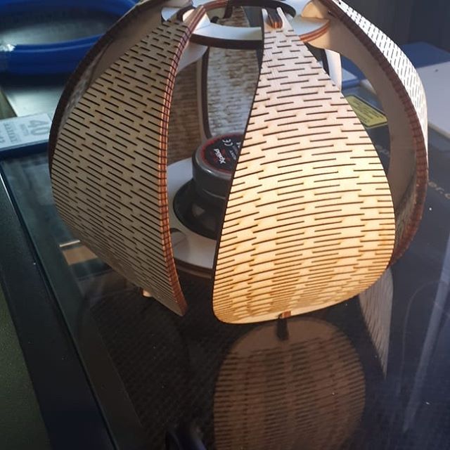
I intended to design something that could hold a speaker driver. I knew tha acoustically a speaker needs to be enclosed in a sealed box, which I couldn’t achieve in a laser cut sculptorial piece, but this was mostly an excercise to test the techniques I wanted to explore.
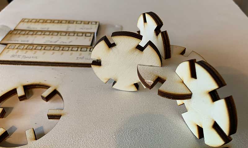
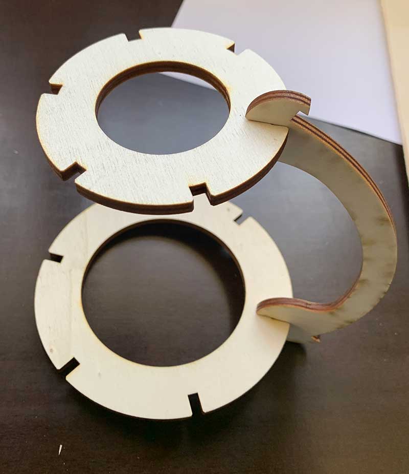
I started by measuring a speaker driver I had available, and designed a ring to hold it, as well as connecting 90º angle pieces.
I also drew a smaller ring and what I called “kerf bent leaves” that would connect both rings, giving it structure and volume.
 |
|---|
| Sculpture Design |
 |
|---|
| Kerf design tests |
Having burnt just one piece of each, I quickly learned that:
- the large ring wound’t be enough to secure the heavy driver
- the 90º connecting piece wouldn’t promote bending of the leaves, as it would simply hold them vertically (hindsight is always 20/20)
- the pattern I tried using for bending didn’t work at all
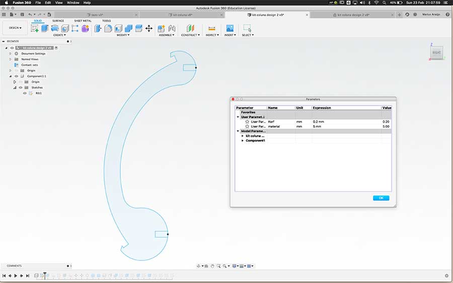
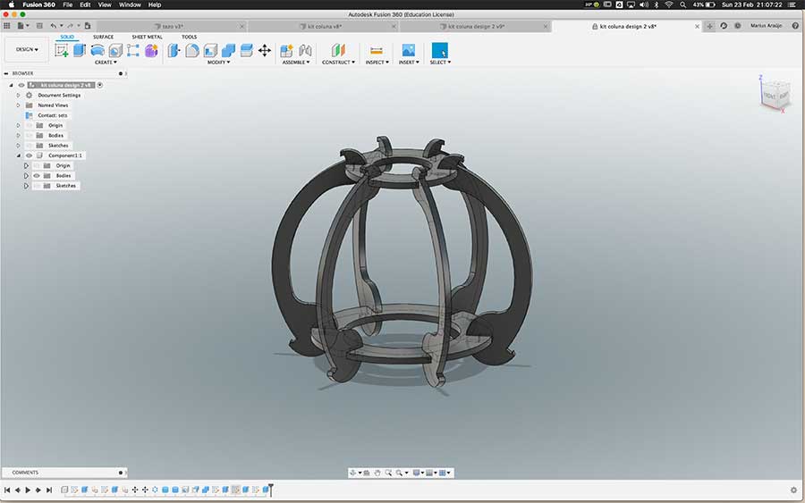
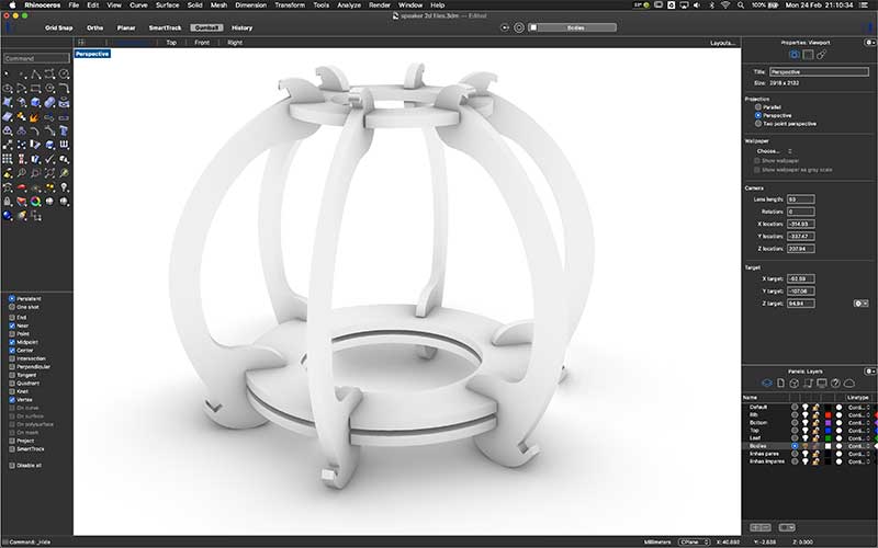
The second iteration was comprised of a rib that would connect the top and bottom rings, and force the leaves to bend around its radius, providing structural rigidity and a holding base for the leaves.
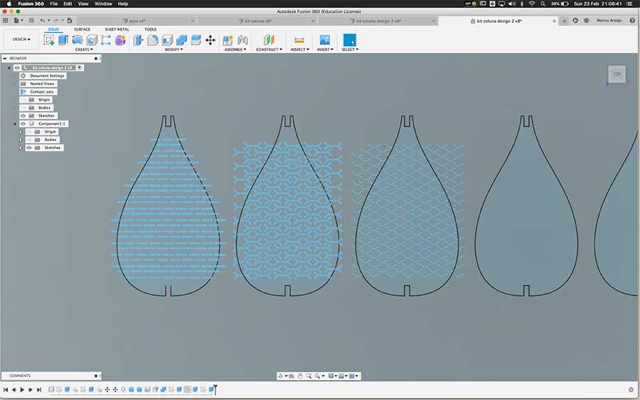
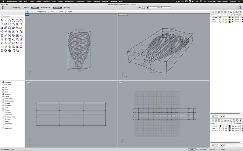
At this point I was also designing the leaves, trying to test several cut patterns in order to achieve good bending but also some tension. These examples proved very stiff, almost no bending.
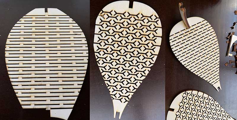
In the next examples I learned that the cuts needed to be more dense but not necessarily large drawn shapes, rather than simple vertically alternated cuts.
I also felt increasingly frustrated with the way Fusion 360 deals with a large quantity of 2d vector shapes, becoming very slow and crashing on occasion. Since the parametric part of the design, the fittings, was done, and all I wanted to try out were different cut patterns in the leaves, I resorted to Rhino 3D, a program that I know well and that handles nurbs vectors with great ease and lightness.
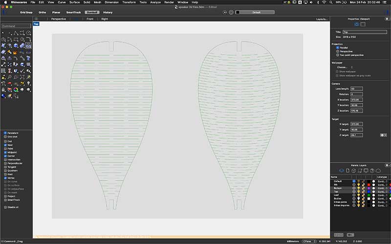 The straight cuts design on the left yelded much more bending compliance. The slightly curved design returned some springiness to the bending, being a little less compliant, while still allowing the material to bend.
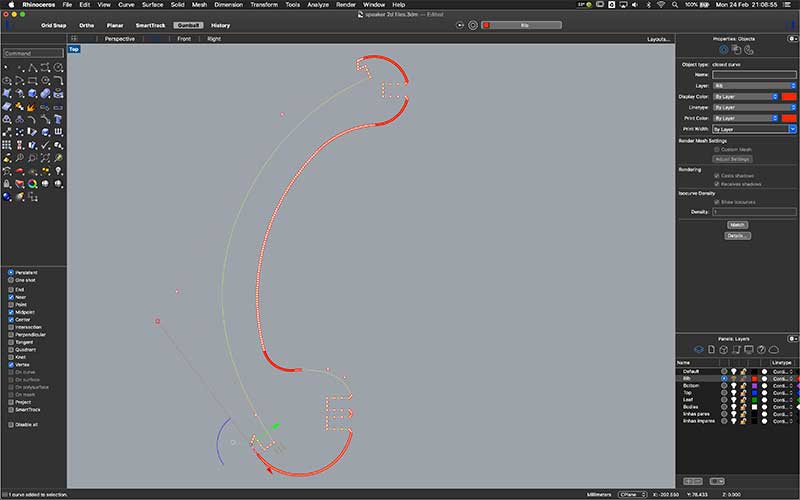
I carried on experimenting with bending the curves, using free form deformation to simplify curve design.
I changed the rib one more time to add a slot for a second bottom ring, in order to secure the audio driver by pinching it between the two rings. Measurements were taken with the Vernier Caliper to determine the distance between slots on the rib.
Vinyl Cutting
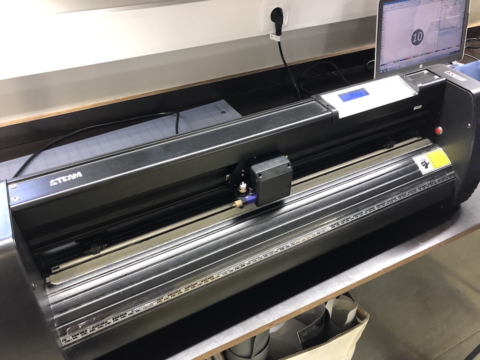
The Vinyl Cutter available at FCT FabLab is a Roland MH 721. It’s Charasteristics are: - Standard blade - Drived by stepper motors - Connects to pc via USB or RS-232 - Max cutting length 243cm - Max cutting width: 62cm - Max pressure: 350grams - Max speed: 121cm/s - Usually controlled via an Inkscape plugin.
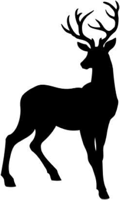
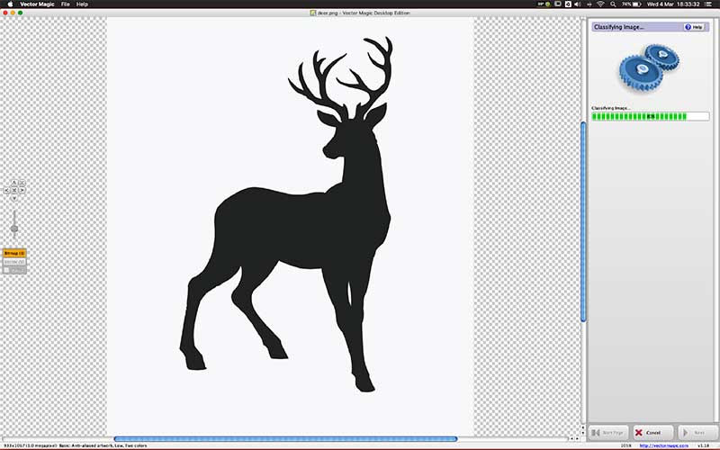
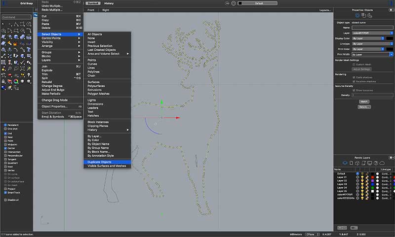
For the vinyl cutting assignment, I started by finding silhouettes of a Llama and a Deer, which I then vectorized in Vector Magick. I edited the results in Rhino, and exported those in DXF, which was then imported into inskscape on the vinyl cutter’s computer, and sent to the vinyl cutter to cut in black vinyl.
 |
|---|
| Llama sillouete found on google image search, on this site |
 |
|---|
| Deer silhouette found on google image search, on this site |
 |
|---|
| Vectorizing in vector magic is quick and easy, but results often need work removing duplicate lines and extra points, which I do easily in Rhino. |
 |
|---|
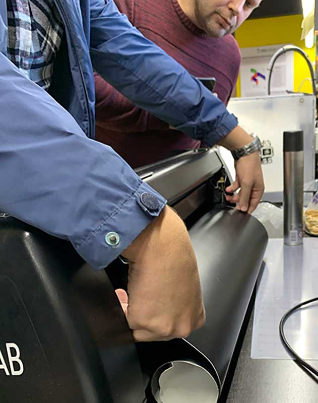
| placing vinyl in the cutter |
|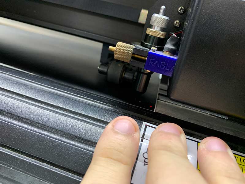 |
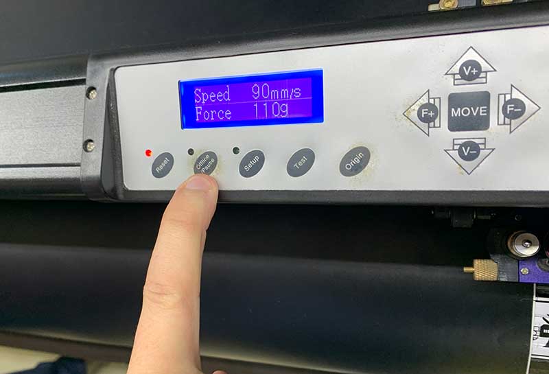
|:–:|
|setting zero point, force and speed|
|
|:–:|
|setting zero point, force and speed|
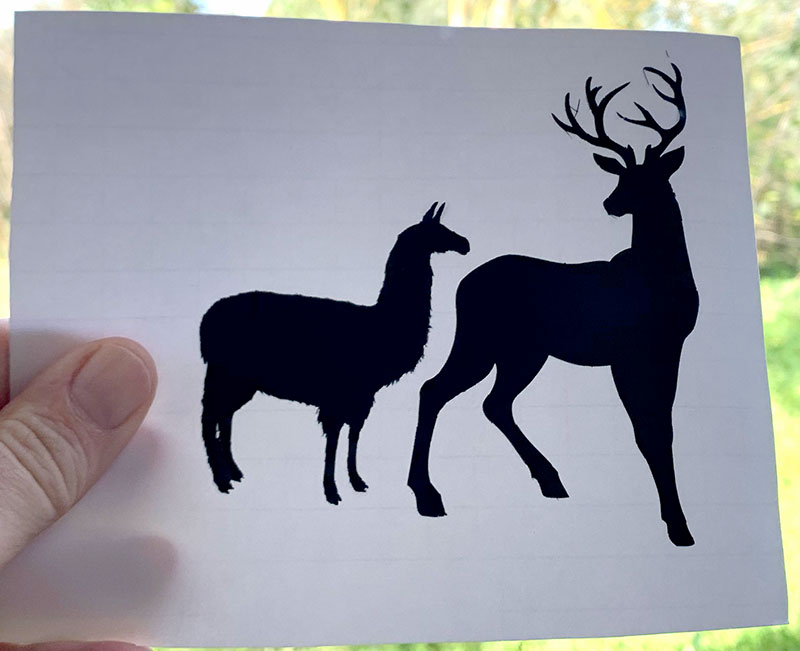 Final result, once the surrounding vinyl was peeled off. Slight “hairs” are visible on the deer antlers, probably from double cuts due to lack of sufficient cleaning of the vector files. The detail on the llama fur is representative of the resolution the vinyl cutter is capable of, quite impressive.
Files
Laser Test Design SVG File Speaker Support and Leafs Design SVG Files Llama & Deer SVG File
Checklist
Group assignment
- Characterize your lasercutter’s focus, power, speed, rate, kerf, and joint clearance
- Document your work (individually or in group)
Individual assignments
- Design, lasercut, and document a parametric press-fit construction kit, which can be assembled in multiple ways. Account for the lasercutter kerf.
- cut something on the vinylcutter
Learning outcomes
- Demonstrate and describe parametric 2D modelling processes
- Identify and explain processes involved in using the laser cutter.
- Develop, evaluate and construct the parametric construction kit
- Identify and explain processes involved in using the vinyl cutter.
Have you
- linked to the group assignment page
- Explained how you parametrically designed your files
- Documented how you made your press-fit kit
- Documented how you made your vinyl cutting
- Included your original design files
- Included your hero shots