Computer-controlled machining
General CNC safety procedures
When working with a large format CNC machine in a MakerSpace, it’s crucial to prioritize safety measures to ensure the well-being of users and protect equipment. In order to operate the machine safely, it it paramount to learn and practise the following:
-
Machine Start-Up and Shutdown: understand the proper procedures for starting up and shutting down the CNC machine, including any warm-up or cooldown processes.
-
Emergency Procedures: understand where the emergency stop button is located and how to use it in case of emergencies, such as equipment malfunction or personal injury.
-
Workpiece Preparation: understand how to properly prepare workpieces for machining, including securing them to the machine bed and ensuring they are correctly positioned.
-
Tool Selection and Installation: uncerstand how to select the appropriate cutting tools for the job and how to install them securely in the machine’s tool holder and spindle.
-
Operating Controls: learn how to operate the machine’s controls safely, including jogging, homing, and setting cutting parameters.
-
Safe Machining Practices: understand best practices for safe machining, such as avoiding reaching into the machine while it’s running, keeping hands clear of moving parts, and never leaving the machine unattended during operation.
-
Tool Inspection and Maintenance: learn how to inspect cutting tools for damage or wear before use and how to properly maintain and store them.
-
Fire Safety: understand fire safety procedures, including the location and proper use of fire extinguishers, and what to do in case of a fire.
-
Cleaning and Maintenance: understand how to clean and maintain the CNC machine, including removing chips and debris from the work area and keeping the machine surfaces clean and free of obstructions.
Group Assignment
Link to group page, which I expand on here.
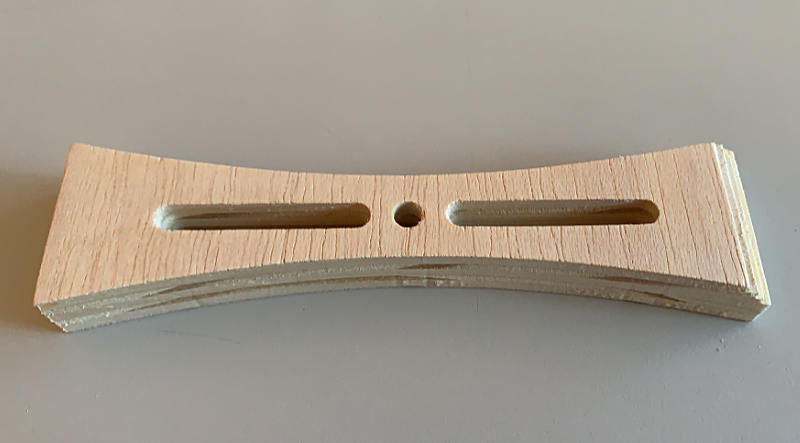
Tiago and I decided to make a work holing clamp in plywood for the XCarve CNC, to test different end-mills, feeds and speeds and evaluate results.
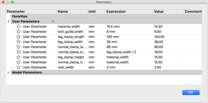
We had 15.3mm plywood stock, so Tiago designed a parametric model in Fusion 360.
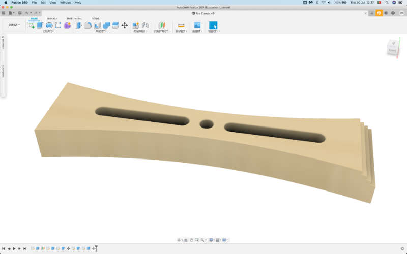
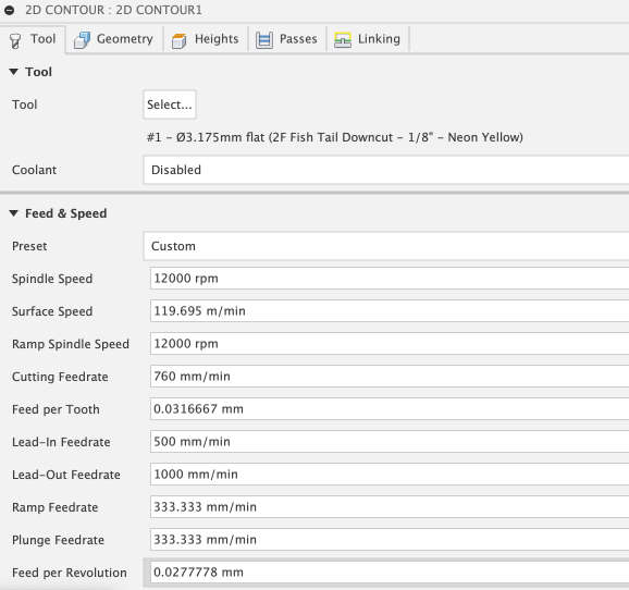
I set up the machining paths in Fusion’s Manufacturing section. First we used Inventables supplied 2 Flute Fish Tail Downcut - 1/8” (3.175mm) end mill . As I didn’t have feeds and speeds for this endmil, I used Inventables own online software, Easel, to determine those, as it is made for their CNCs and mills. Easel lets you select the material, plywood, and one of their mills. Unfortunately it didn’t have the 2 flute fishtail, so I selected a 2 flute and the software gave me very conservative but safeish feeds and speeds, which I plugged into fusion.
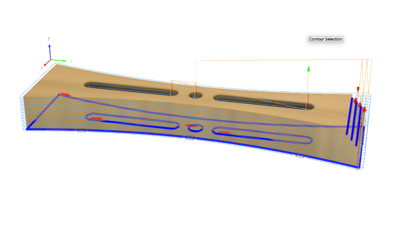
In Fusion I decided on a 2D Contour operation, selecting the base curves as contour chains, as well as the clamping steps’ edges, as shown in the picture below. This proved an efficient path for machining this model in a single operation.
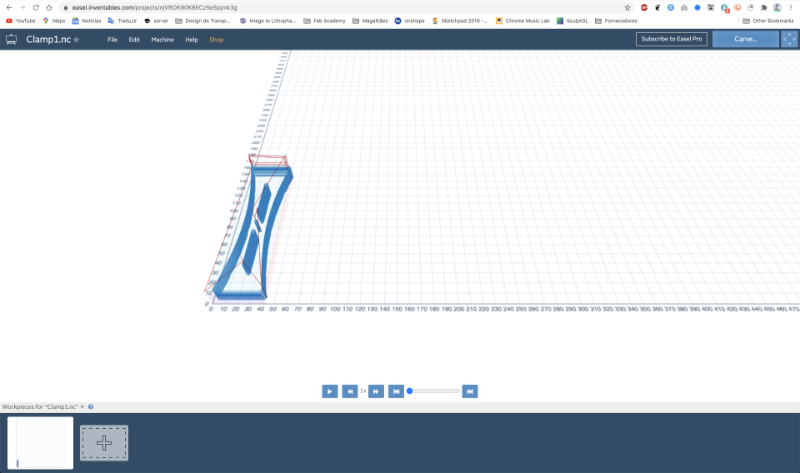
I determined the contour would happen successively in multiple depths of 0.7mm, which, with the cutting feedrate of 760mm/min, resulted in a simulated 20 minute cut for this piece. I then exported the paths from Fusion through the easel post processor, and imported the resulting NC file into Easel, after logging in through inventables.
After screwing down the stock, setting the X and Y zeros manually and the Z zero with XCarve’s probe, I sent the job to be carved.
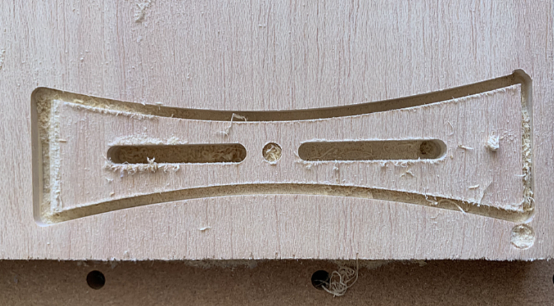
The resulting cut seemed dimensionally correct in x and y, but didn’t make it through the stock, missing the bottom by about 1mm, enough for the piece to not detach from the stock. Cut quality wasn’t flawless as there was a bit of wood burr, but that could easily be cleaned off with sanding.
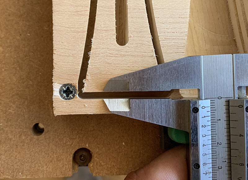
Runout is a rotation inaccuracy which occurs when the tool is no longer aligned with the main axis. In drilling applications, this can result in a bore diameter that is actually larger than the drill’s nominal diameter.
We measured the distance between the edges of the contour cut and compared that with the width of the endmill, which turned out to be virtually negligible, meaning there is no measurable runout, at least with the caliper we have. For the next test I used a single flute end mill, Inventables’ Gray 1/8”, for which easel was prepared to give more aggressive feeds and speeds of 1016 mm/min of feed rate, 304.8mm/min of plunge rate and 1.3mm depth of pass, which I again plugged into fusion on a new 2d contour tooling setup. I went back to Tiago’s design and changed the material width parameter to 16mm, in order to force the XCarve to go through the material. I repeated the export from fusion / import to easel game, set new zeros and machined the part again.
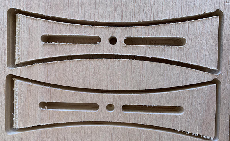
This time the cut had similar light burr, but the less conservative feeds and speeds resulted in a 10 min cut, effectively halving the necessary time. Also the cut went almost all the way through, and the tabs I had set in fusion worked well, keeping the piece in place.
I then decided to up the ante and increase speeds slightly, trying to get a faster or cleaner cut. I used the same end-mill as in the second operation. I also increased the material width to 16.5mm, trying to force the machine to cut through the stock, into the sacrificial board. Simulated time was 9 minutes, so I went ahead and sent the job to XCarve again.
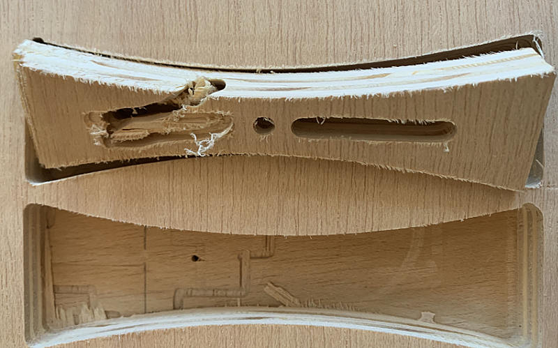
Disaster struck at the very end of the cut, as I’d forgotten that the increased material width meant that the tabs I’d programmed were too low, nearly on the sacrificial board, meaning there was very little material holding the part to the stock after the external contour pass. I probably wouldn’t have noticed if that was the last part of the path, but as there was another interior hole to cut, by then the part was loose and the result can be seen in the picture. Luckily I was there as it happened and I managed to halt the machine on the big red panic button, preventing damage to the end-mill. Still, burr wasn’t any less, so I figured there was little to gain from further tests.
Individual Assignment
Something small
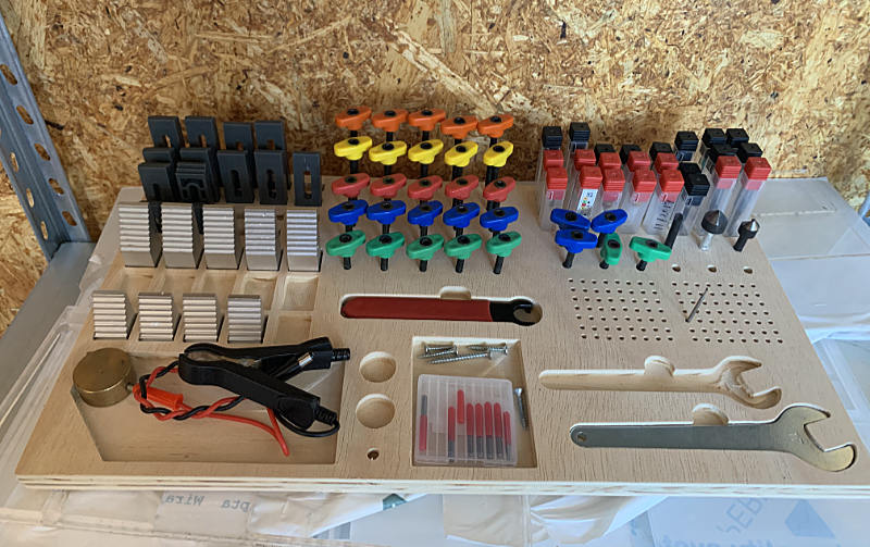
At my fab-manager’s suggestion, I machined a tool holder for the bits and clamps used by both CNCs in the fablab. They were scattered around the machines in little impractical boxes and I agreed that they needed some organization to make oversight simpler. I went to Inventables projects site and found Glen Powell’s design, which I copied to Easel and adapted to the stock we had available. I added some more placeholders to adapt the design to our needs, as in the screenshot below:
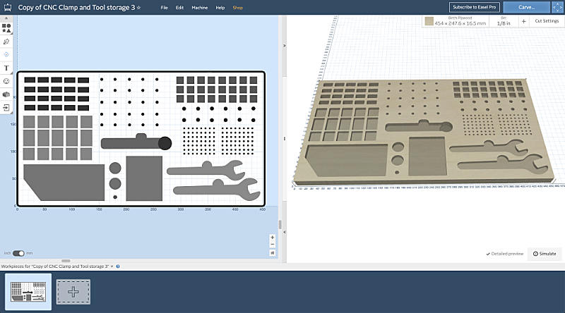
From this exercise I understood that Easel is a practical and easy designing tool for the inventables CNCs, like Carvy or XCarve. One can make simple shapes which you can pocket or contour to a depth determined by the shade of gray to black on the design, which is converted to exact depths. I set the origin as previously and sent the job to the machine; Nearly 5h later, it was complete.
Something Bigger
Pronum CNC
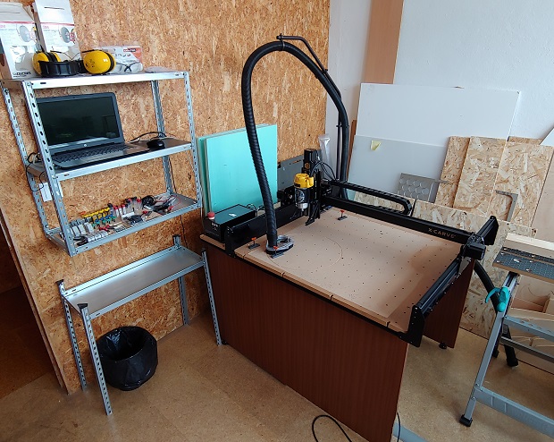
For my make something big project, I decided to use our Pronum CNC machine, at _ARTERIA_LAB, where I work.
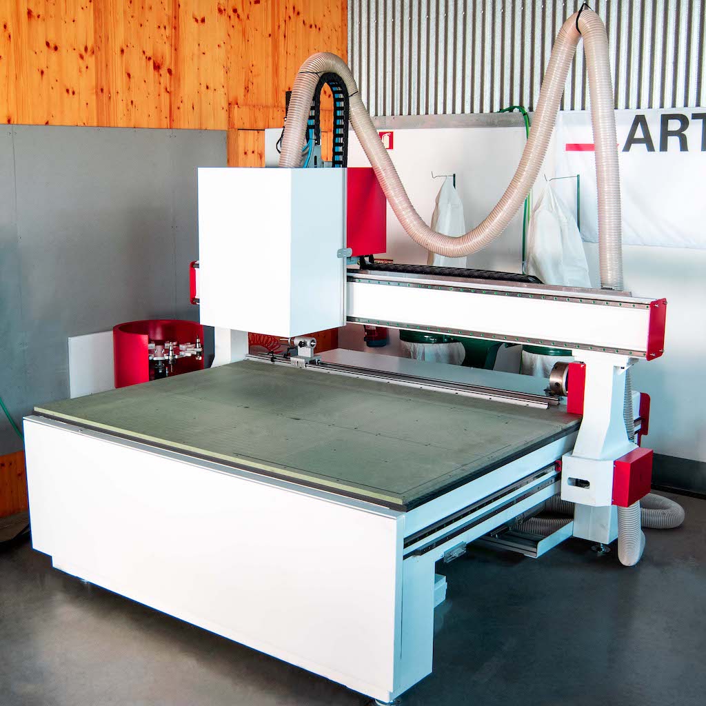
Pronum is a Portuguese manugacturer, who builds custom machines to specification. In out case, the characteristis are:
- Working area of 210 cm x 130 cm x 30 cm
- 4th rotary axis in the rear of the CNC
- Automatic tool changer of up to 10 tools
- 5,5Kw HSD Spindle, capable of 24000 RPM, with ER32 Collet
- Vacuum table
- Integrated particle extraction
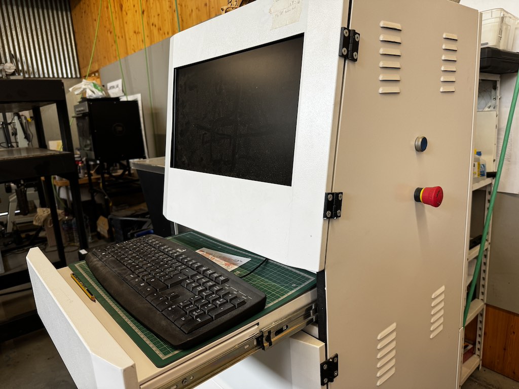
- Dedicated control computer with cabinet (where the emergency stop is located)
Flat Pack Chair
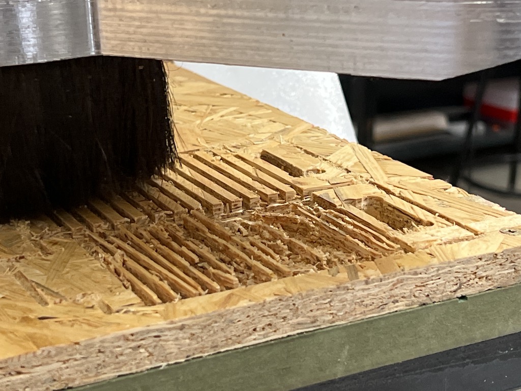
I decided to make a flat pack chair useing OSB, or Oriented Strand Board, because it was the only material I had lying around. It was the packaging for our Trotec laser Machine, and I thought it’d be nice to recycle into a new project. I didn’t find much documentation online about milling OSB, and I came to understand why… It’s not a great material to work with. OSB is composed of pieces of wood leftovers, fixed with bonding resins and compressed into boards. When you mill it, it lets itself be cut easily, but it’s not very structural, edges easily frey and are generally fragile. Yet, I did manage to use it.
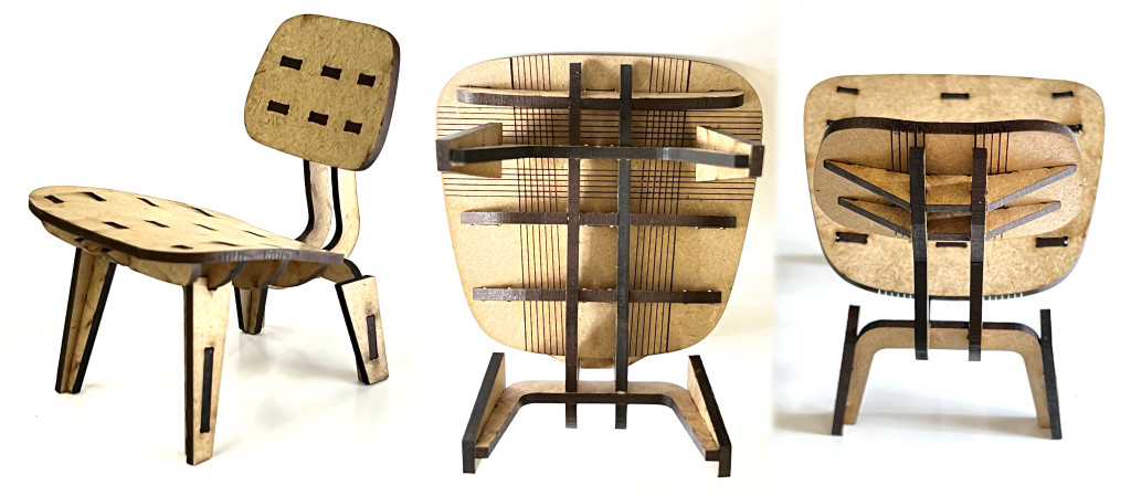
As a Design enthusiast, I like the so called easy chairs, which have low back legs and give the user a reclined, relaxed seating position.
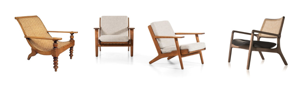
I’d seen a Popular Mechanics article years ago, about CNC milling a Flat Pack Chair inspired on the Eames LCW (Lounge Chair Wood). That article seems to sadly have been semi-lost, but I found another one on the same topic. I then tracked down the author of the Flat Pach Chair, John Thomas Heida and realized he has the design files for sale on his website. His work is inspiring, so I bought the DXF files.
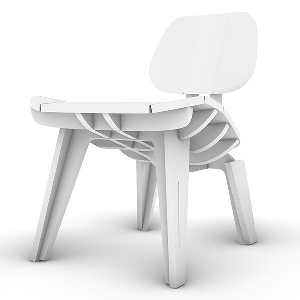
The original design consists exclusively of flat pieces that you cut and puzzle together.
I wanted to change the design so that some of the parts were curved. I sought to achieve this by milling grooves on the surfaces almost all the way through, so as to weaken the part enough to bend, a little bit like Kerf bending on the laser.
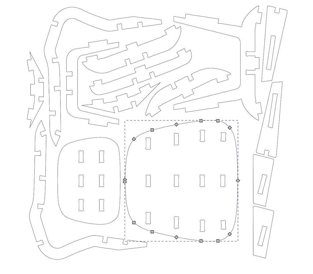
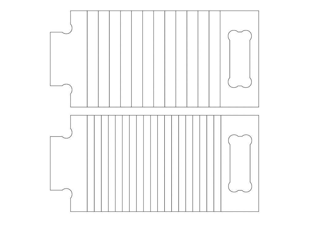
I imported John Heida’s file into Rhino and redesigned the many individual back and bottom surfaces into just two pieces. I had to be careful that the many dogbone parts stayed in place, in order for the puzzle to go back together properly.
On Dogbones and Teebones to overcome fillet issues
In CNC machining, the tool diameter determines the minimum achievable corner radius, the tool cannot create a sharp inner corner, always generating a sort of fillet. In order for a right angle part to fit in a machined hole, notches have to be added at the corners, creating shapes that look like graphics of bones or tees. Hence the name Dogbones or Teebones
This site explains it very well, and provides us with these handy graphics:
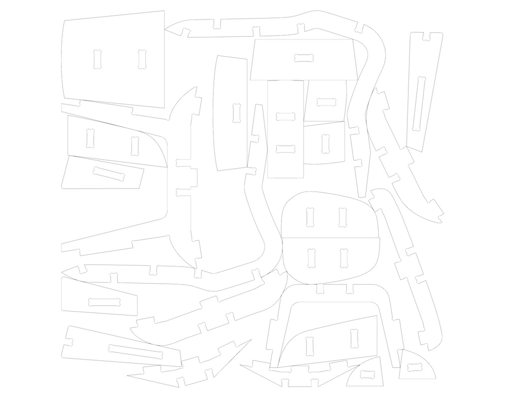
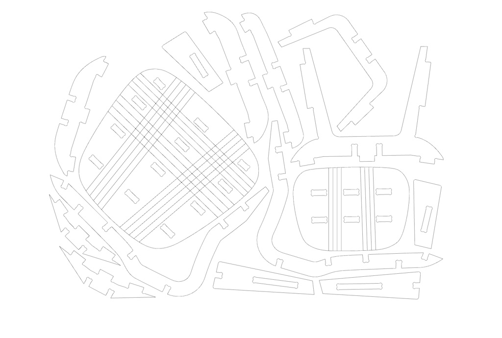
I also had to redraw most of the vector shapes, as the original DXF file had millions of small straight vectors, and that made the file very inefficient and heavy.
It looks similar, but redrawing almost everything took some time and made a big difference in the quality of the vectors.
I added the kerf bending lines and scaled the whole model so that I could test it quickly in 3mm MDF on the laser cutter.
Having successfully tested the design on a small scale, I decided to test kerf bending OSB. I measured the OSB with a caliper, across several points, to be 15.3 mm, so I determined that that would be the right thickness. I made two tests in order to figure out how far apart to set the kerf lines for the real chairmore: one with tightly drawn lines, and one with a little more spaced lines. I also wanted to test if the dog bone would fit tightly with the material width, so I designed a little test for that as well.
Clearly, the tight design was unsatisfactory with this material.
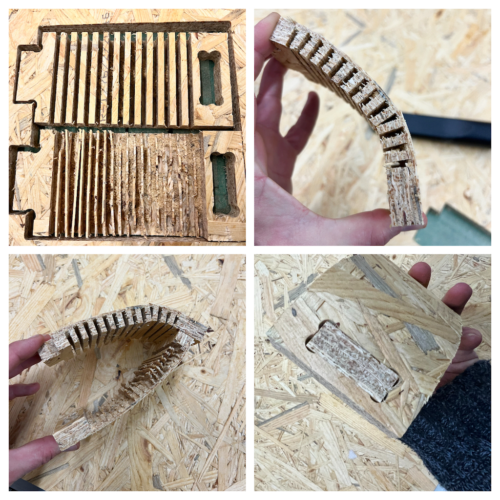
From this test I determined which distance and depth between cuts was adequate for the angle of bending that I needed to have, and that the dogbones produced a tight friction fit, which was great!
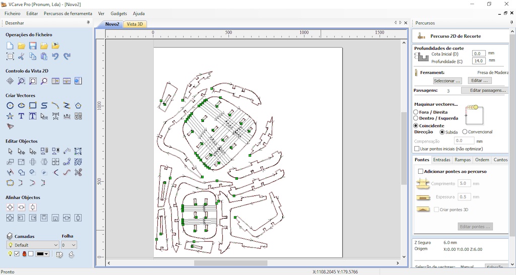
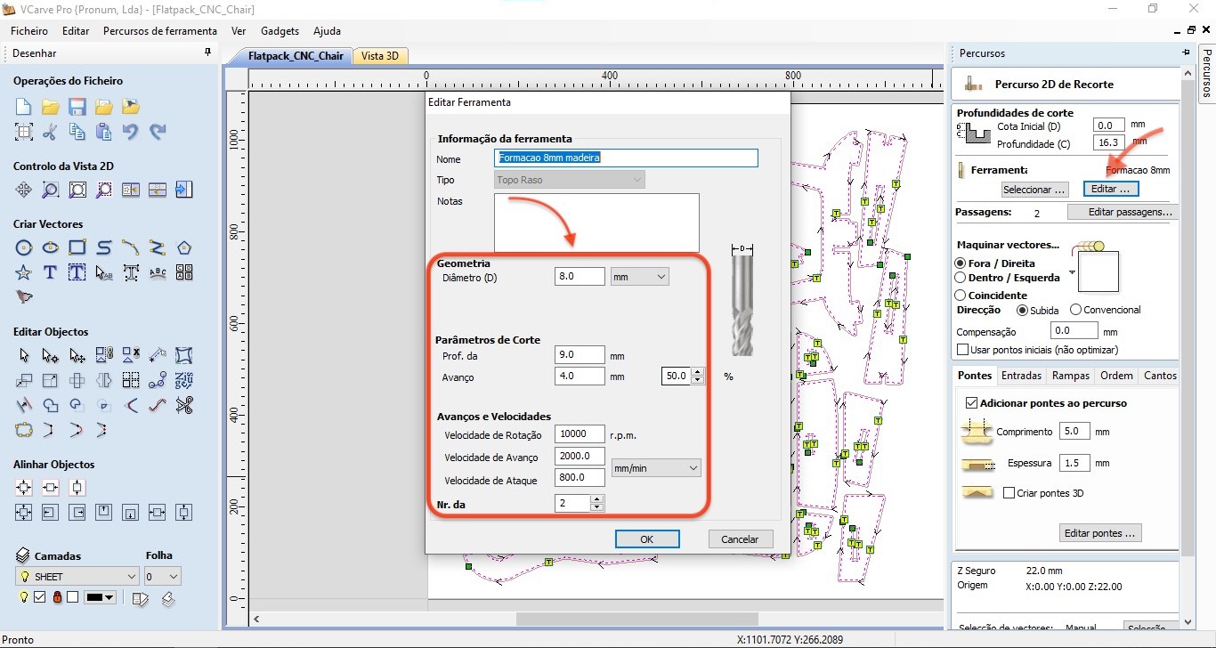
I then adapted my design and exported it in Dxf format, which I then opened in VCarve, the software we have to prepare files for our Pronum CNC.
In VCarve I set up two jobs, one for the kerf cuts, which I would mill coincidentally to the lines up to a certain depth, and another for the perimeter cuts, where I would cut on the outside of the lines, over 3 passes, to the full material thickness. I left some tabs, so that the pieces didn’t come loose during the cut.
I then setup the feeds and speeds for this mill bit on OSB, which I calculated in the Fablab Speed and Feeds Calculator, converting the imperial/metric values I got at the time.
Finally I exported the nc code with the Eding CNC post processor, which is the one that our cnc understands, and opened it in Eding CNC.
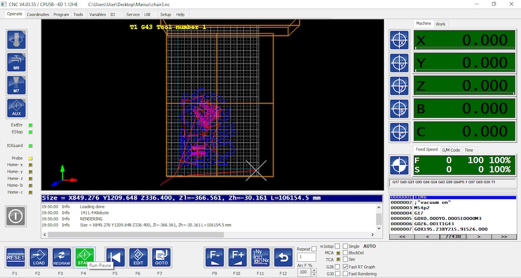
This is a fairly complex and retro looking user interface, but it works once you wrap your head around it. I zeroed all the axes where I wanted the machining to start, and pressed start.
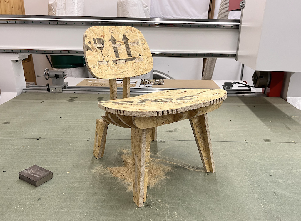
Once all the parts were cut, I sanded the edges in order to smooth some wood burr and sharp edges, and assembled the puzzle. I was pleased with the result, but one thing that didn’t go well is that the front edge of the seat doesn’t match the front legs. The seat and back do bend to conform with the other parts’ curvature, but material thickness prevents the front holes to match, so I’ll have to distance them a little further to the front when I redo it, preferably in plywood, which is a much stronger and prettier material.
Files
- Glen Powell’s CNC Clamp and Tool storage SVG file
- My kerf testing design in DXF and SVG
- My final design of the chair, in DXF and SVG
Checklist
Group assignment
-
Test runout, alignment, speeds, feeds, and toolpaths for your machine
-
Document your work (in a group or individually)
Individual project
- Make (design+mill+assemble) something big
Learning outcomes
-
Demonstrate 2D design development for CNC production
-
Describe workflows for CNC production
Have you?
-
Linked to the group assignment page
-
Documented how you designed your object (something big)
-
Documented how you made your CAM-toolpath
-
Documented how you made something BIG (setting up the machine, using fixings, testing joints, adjusting feeds and speeds, depth of cut etc.)
-
Described problems and how you fixed them
-
Included your design files and ‘hero shot’ photos of final object