This week’s assignment is to write an application that interfaces a user with an input and/or output device.
I choose to use the MITapp inventor, and later developed a simple GUI using Processing.
App Scheme
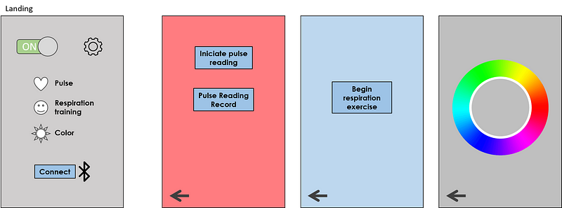
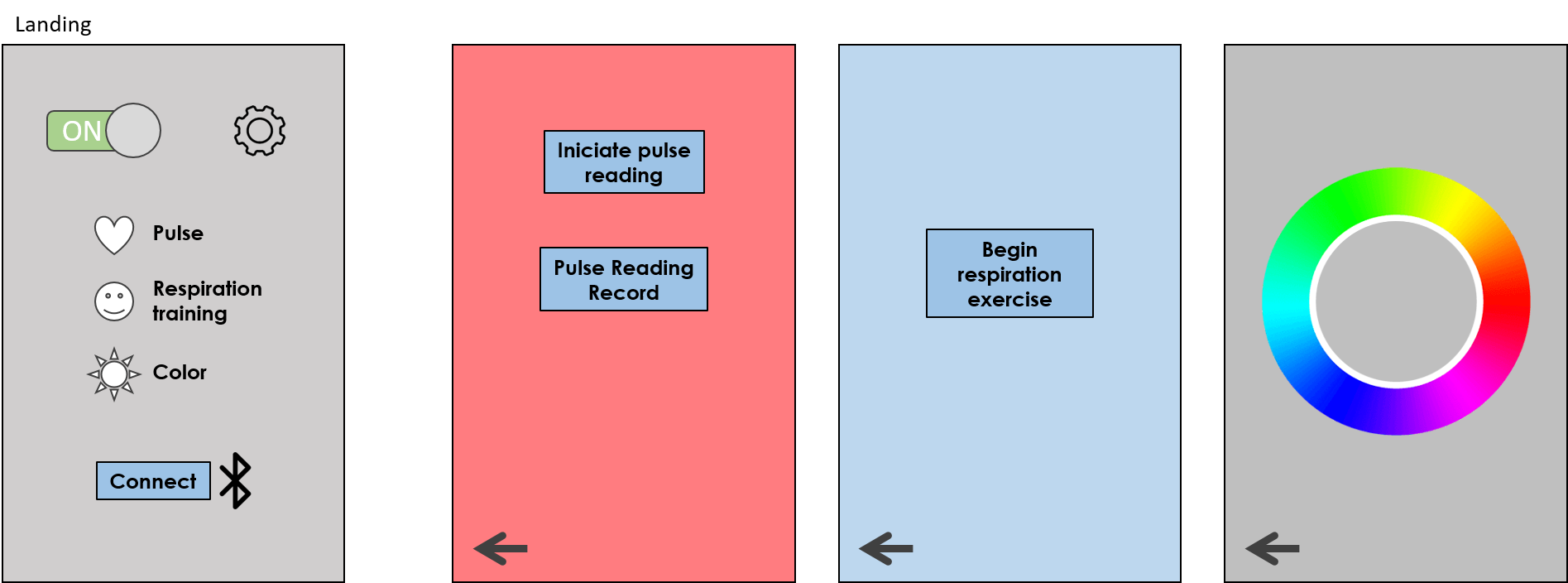
I would be working on the first version app for my final project: The office mood lamp. First, I sketched a map of the app functions and some of the features that could be customized.
The office mood lamp is a desktop device (or a tangible user interface) that could read stress levels and help to manage them by assisting in breathing exercises with tactile and visual stimuli.
The app needs to:
Turn the lamp on and off and pick the light color
Trigger a pulse reading (connect to the pulse sensor in the device and show the sequence with LED pulses)
Manage and show these stress historic measurements
Trigger a breathing exercise (connect to the actuator in the device and activate the sequence with LED pulses)
MIT App Inventor
I decided to do my first try with the MIT App inventor because it looks easy to learn.
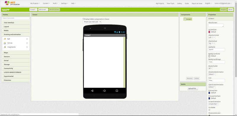
For testing the APP on an Android device we need to install the MIT AI2 Companion, this allows us to synchronize the programming changes made on the PC with the GUI on the mobile device. By default when I created a new project a new screen is created, this will be my landing screen.
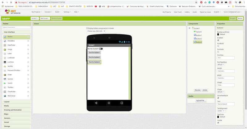
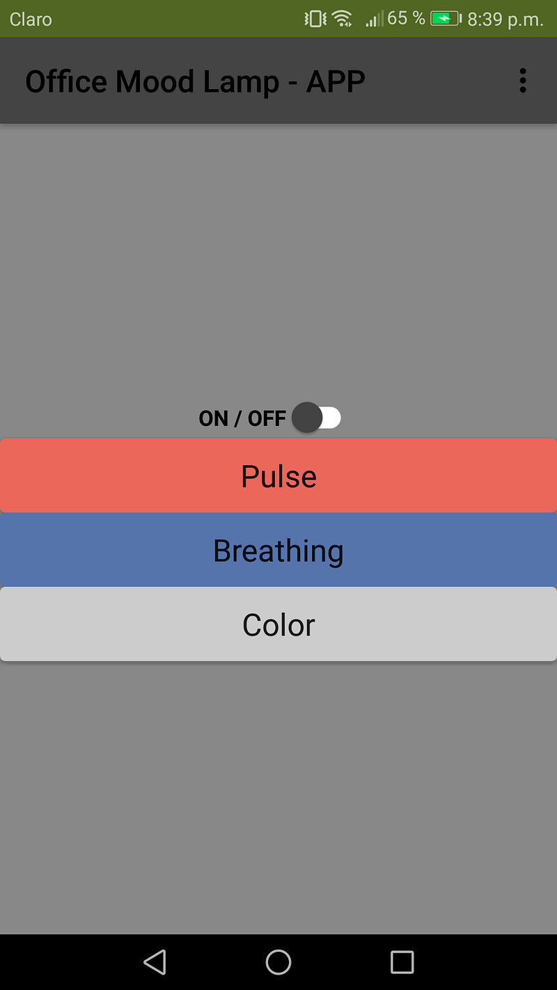
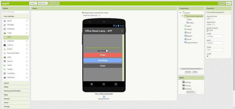
At first, I created buttons on the landing screen, my scheme has one switch and 3 buttons (the connect and configuration buttons will be added later).
We drag these components from the left side of the screen, under the tab user interface to the phone mockup. In the right-side panel, we can change the features of the buttons like text, size, color, position.
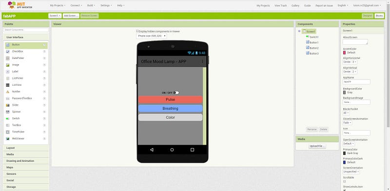
Here is the result after some tweaking:
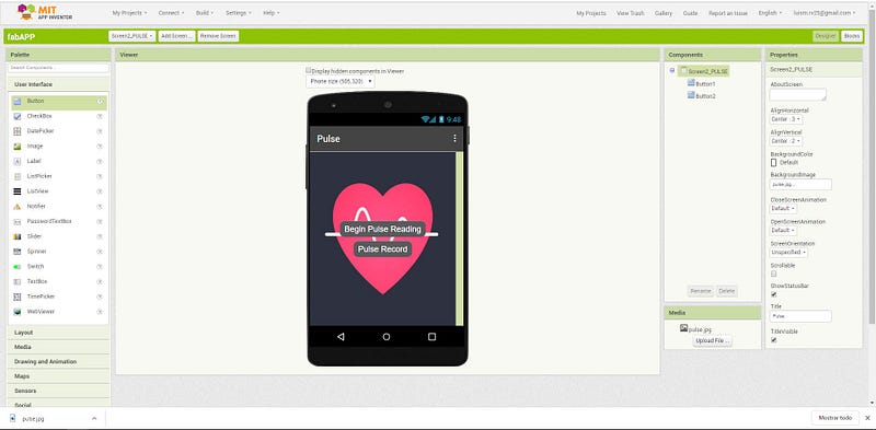
Next, I created a second screen to connect the pulse button as shown in the scheme. I added a background image and customized the buttons like on the landing screen.
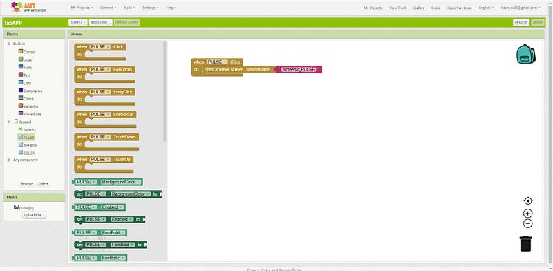
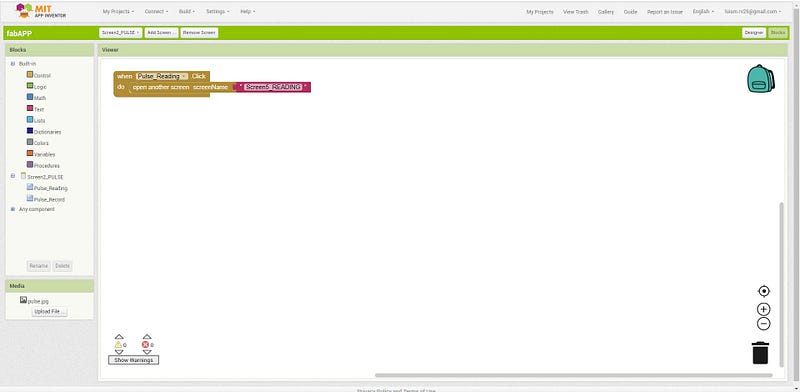
Now, to connect the buttons on the landing screen to the second screen, we need to change to the BLOCKS view to program the actions. The blocks button is on the upper-right side of the screen.
To create actions, we need to drag and drop the blocks to the screen, as we are on the landing screen I selected the PULSE button action from the left side of the window. The first action to perform when the PULSE button is clicked is to change to the second screen.
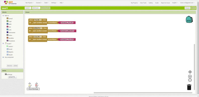
I copy and paste the blocks for the breathing and color buttons and created their matching screens, to be customized later.
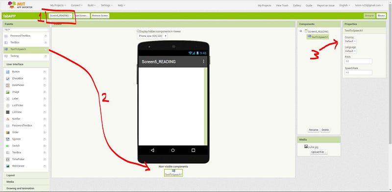
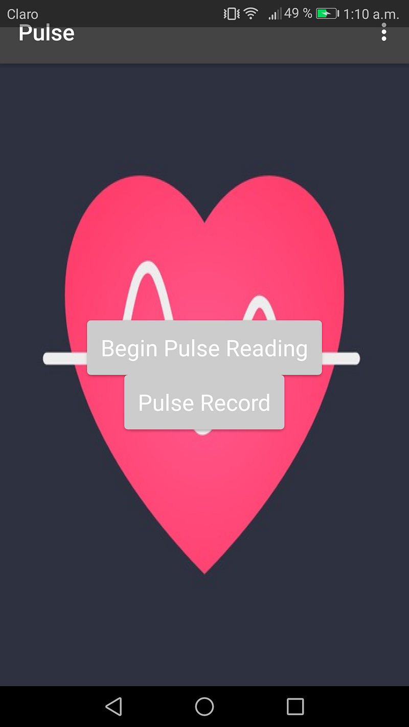
For the PULSE screen, I created the same action to direct the BEGIN PULSE READING button to another screen, which would indicate the user the actions to follow, this is made with a component called text to speech in a new screen.
To activate the text to speech component drag and drop to the screen and change the language properties, then go to the blocks view and set the action.
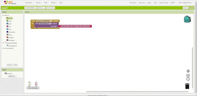
The text to speech would begin as soon as the screen is active, so we drag the block from the screen actions list and then a block from the text to speech component (purple) and added a text block (pink) to contain the message to read aloud, in this case: “place the index finger on the pulse sensor”
As we need to get feedback from the pulse sensor to continue the reading, but I was not quite sure how to make this connection, or where it should be (right at the landing of course!) So, I look up a tutorial on Bluetooth communication between the app and another device.
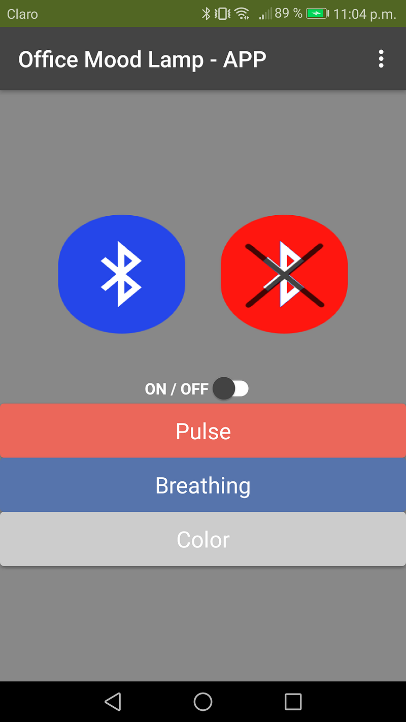
I followed this tutorial on how to set up a Bluetooth connection screen. I added some icons for the Bluetooth buttons but somehow these are not showing correctly on the browser but look good on the phone.
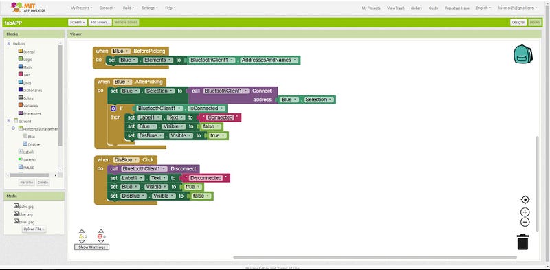
Now that I got the Bluetooth connection buttons on the app and blocks I need to figure out how to actually read and send data between devices using Bluetooth.
Notes:
The Bluetooth device needs to be previously paired to be discovered by the app.
The Bluetooth connection is lost if you change screens! This would be really annoying for my scheme, as I planned different communications on different screens I would need a connect button on each screen. Maybe a solution is to get a scrollable (but long) single screen.
I found this tutorial (in Spanish) with good examples of sending numbers from the phone’s app to an Arduino and sending text messages from the Arduino to the app.
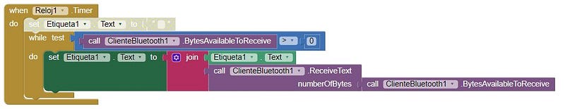
The block looks like this to receive a text from the Arduino:
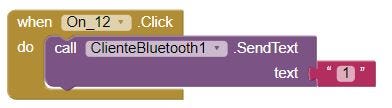
To send a text (preconfigured) to Arduino when pushing a button:
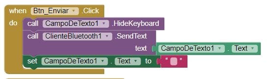
To send a text to Arduino by typing and hit the send button:
These blocks would be incorporated into my app in the pulse reading (receive a signal from the pulse sensor).
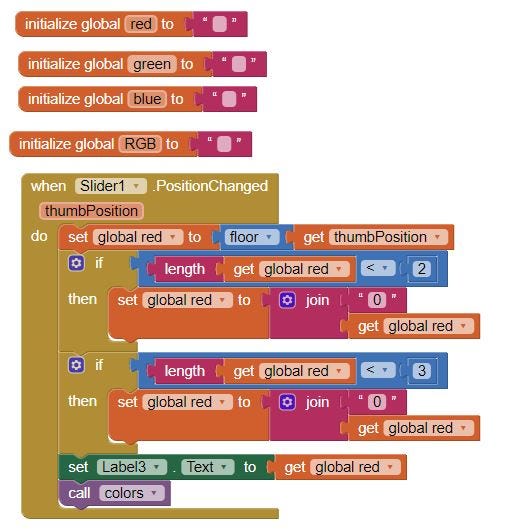
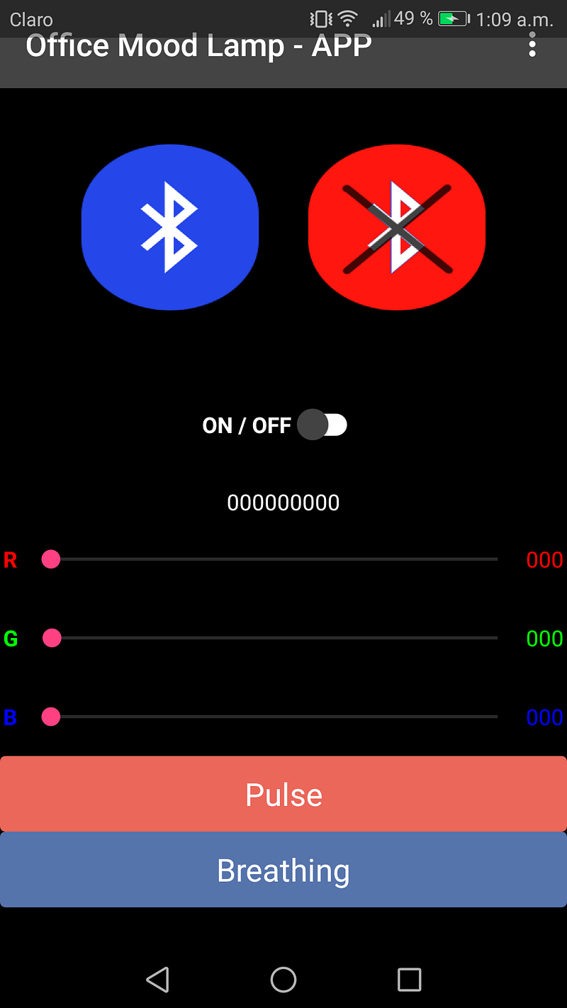
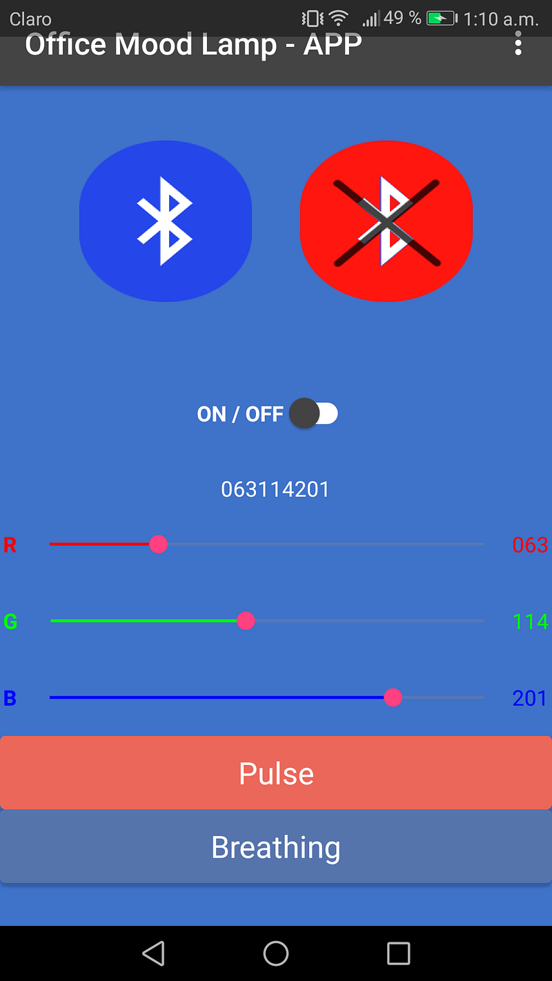
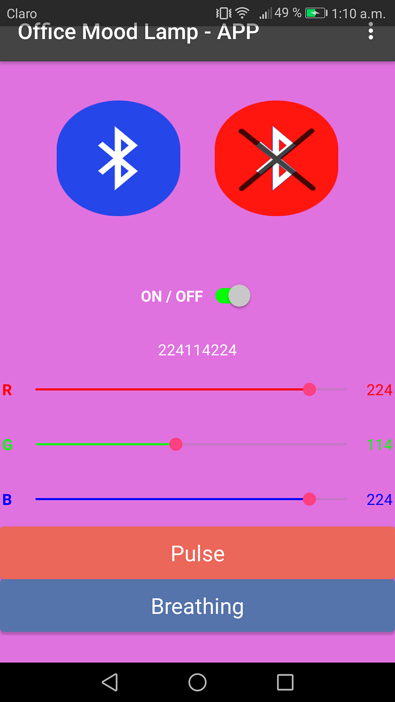
Another feature planned was to change the lamp color, the initial idea was to set a color wheel to select a color hue, but instead, I decided it would be better to use 3 sliders with values from 0 to 255 for each LED color (Red, Green, and Blue).
The slider blocks work like this, first declare a variable for each color, and a fourth to the RGB value. The block completes the “0” to get a 3 digit number for each color and shows the value in a label next to the slider.
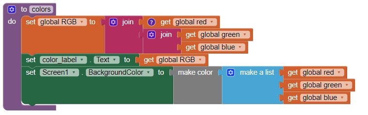
A procedure named COLORS is created to get the value from the 3 sliders, this 9 digits combined value will be sent to the device by Bluetooth, and also changes the hue of the app background.
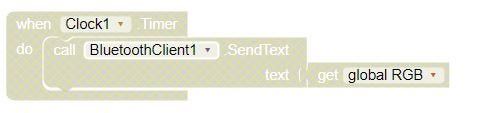
I do not have a device to connect or test the app so blocks corresponding to Bluetooth communication are disabled. this one is supposed to send the digits to change the color.
Here’s a little demo video of the working app:
And some screenshots:
Download the APP
You can download and try the Office mood lamp app here on .aia format (MIT App inventor) or .apk (to install on an android device)
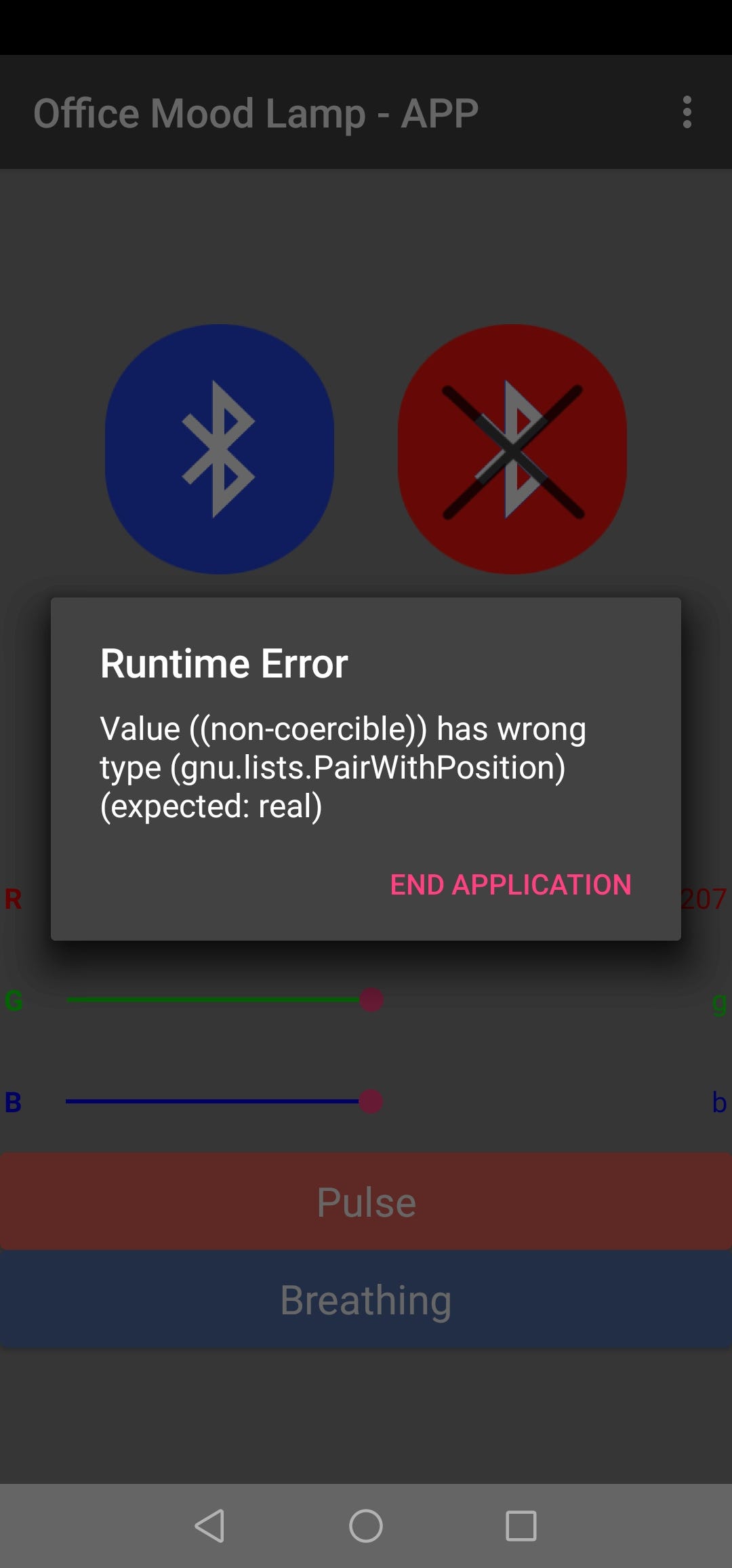
After testing the app a year later, something broke, the moment I test the sliders for the RGB the app shows an error.
Processing interface
So I decided to replicate the slider control with processing. I will be using the Neopixel ring that is going to be part of my final project, and continue with the programming shown in the Embedded programming assignment.
The idea is to have a simple GUI that let us choose an array of colors by clicking on a color wheel, similar to our first mockup.
After some research, I found that fellow FabAcademy students have made similar approaches using neopixels and processing, like Mai Nguyen and Yuki Oka.
The first step is to set up an Arduino — Processing communication. The Arduino will control the Neopixel ring, but processing will show the GUI and send the data for the RGB colors to Arduino.
I’ve used this Sparkfun tutorial as an Introduction Guide to connect Arduino to Processing.
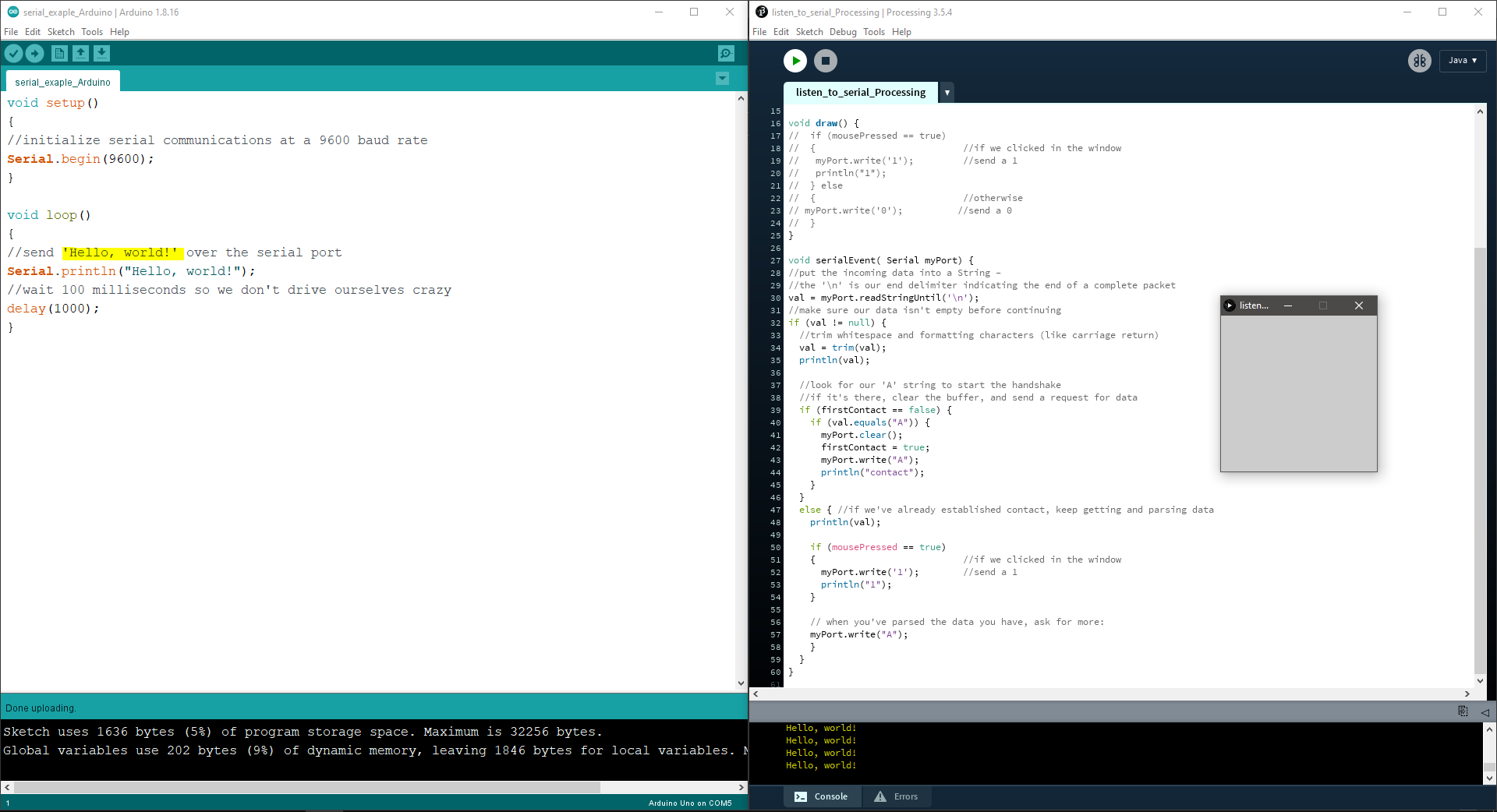
The example consists of a simple handshake, between Arduino and Processing, in which the Arduino sends a string over the Serial port, and it's read by Processing. The next step is to, send data the other way around, from Processing to Arduino.
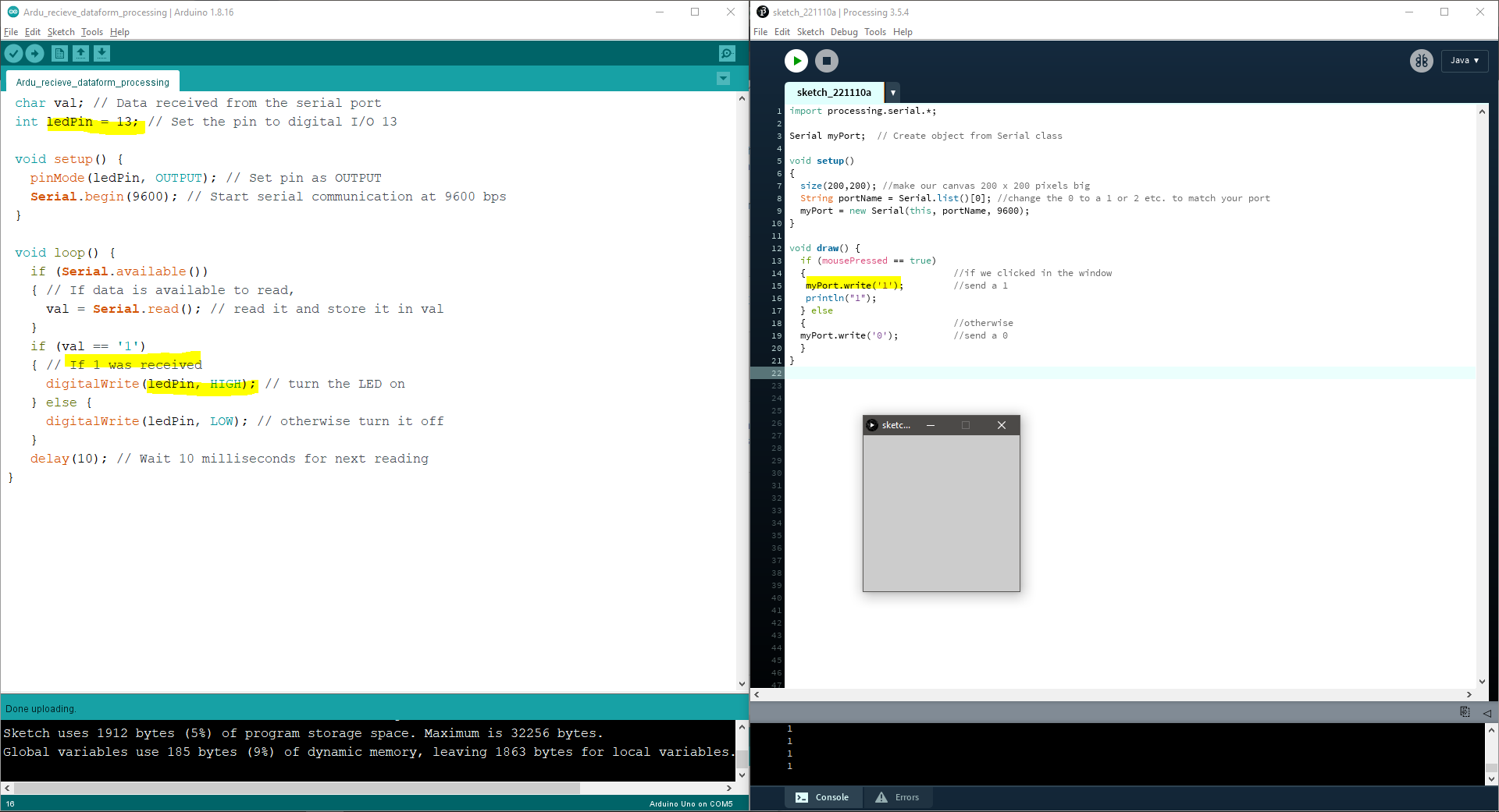
So, in this code, I programmed processing to send a “1” from the Serial port every time we click on the Canvas, this value is read by Arduino, and blink the pin 13 LED every time a “1” (or click) is sent.
There is a way also to send information between the Arduino and Processing at the same time, this sort of handshake is the basis of our code.
I started with Yuki code, that's already based on NeoPixel Ring simple sketch by Shae Erisson and provided in the Neopixel Library as an example.
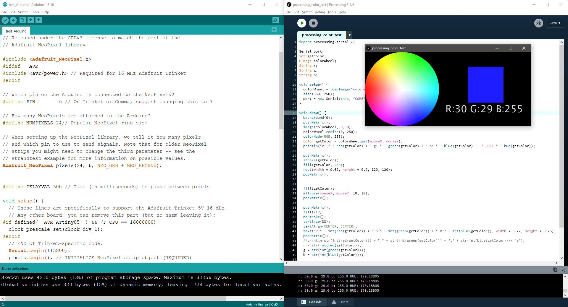
Processing base code
The Processing code works by loading a color wheel image on the Canvas, like this one, when the mouse clicks on the image the color is stored in Processing in its R+G+B values (0–255) and sent to Arduino as a String.
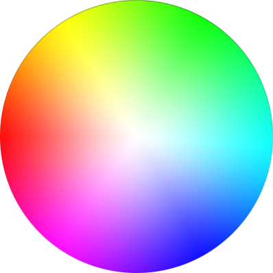
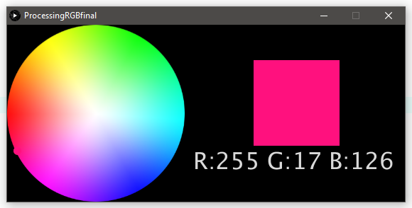
Also, there's a square next to the wheel that shows where the color is the tip of the mouse is positioned to have better control.
The GUI looks like this:
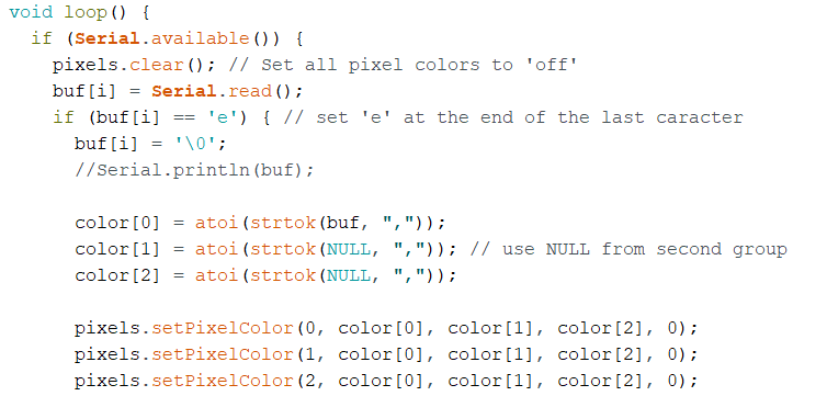
Arduino base code
Using Serial.available(), the program would run if the serial data is sent to Arduino from Processing.
The data was sent as a RGB sequence from Processing so it had to be divided. A strtok() function is used to divide it by commas. and then the divided pieces were converted from string data to int data by atoi() function and put into the array color[].
Finally, the divided data used in the code for Neopixel.
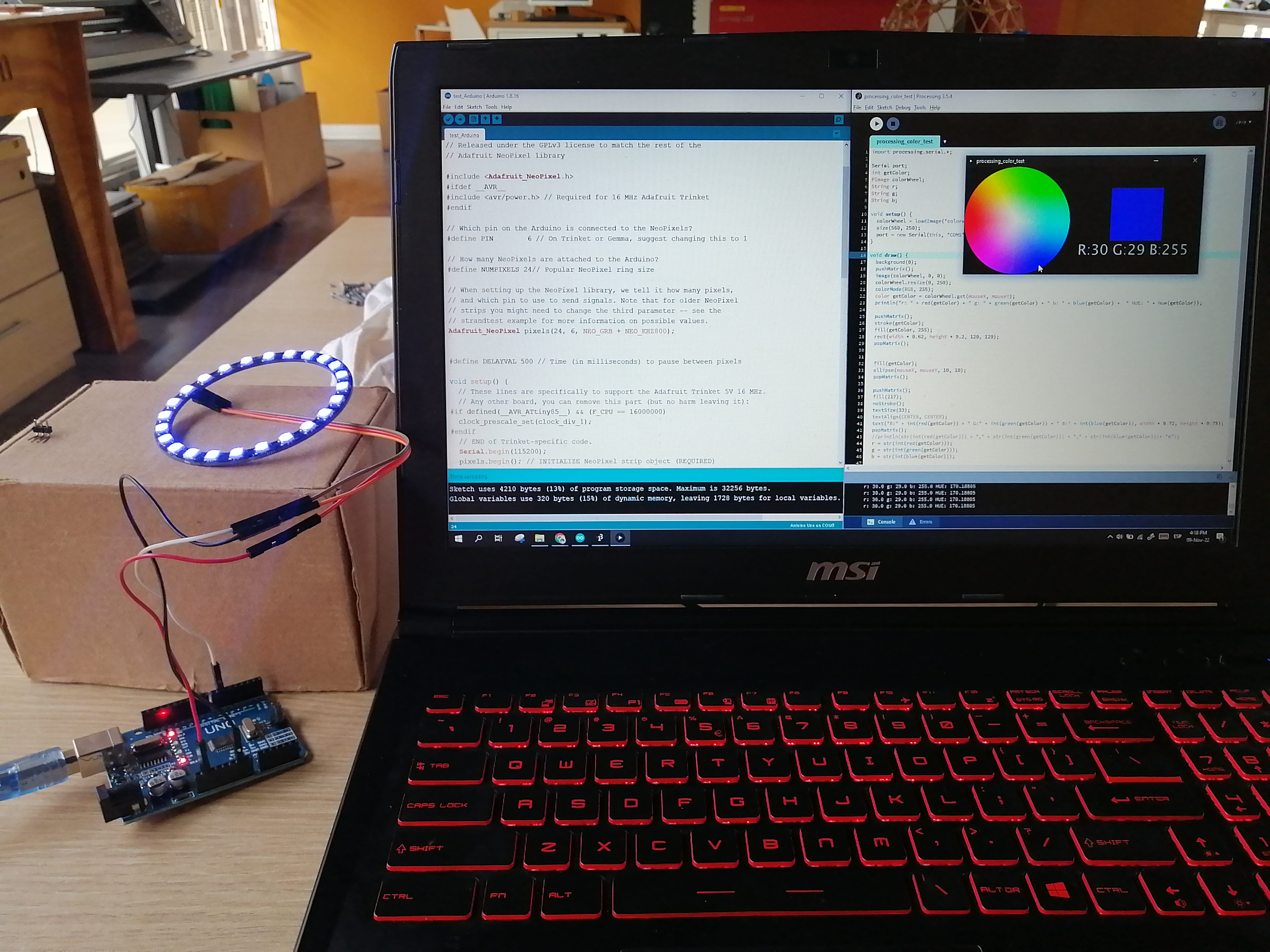
Editing and testing
After some tweaking, I managed to get communication between Processing and Arduino, but only 4 of the pixels went on and the colors were all over the place, so there was some communication error.
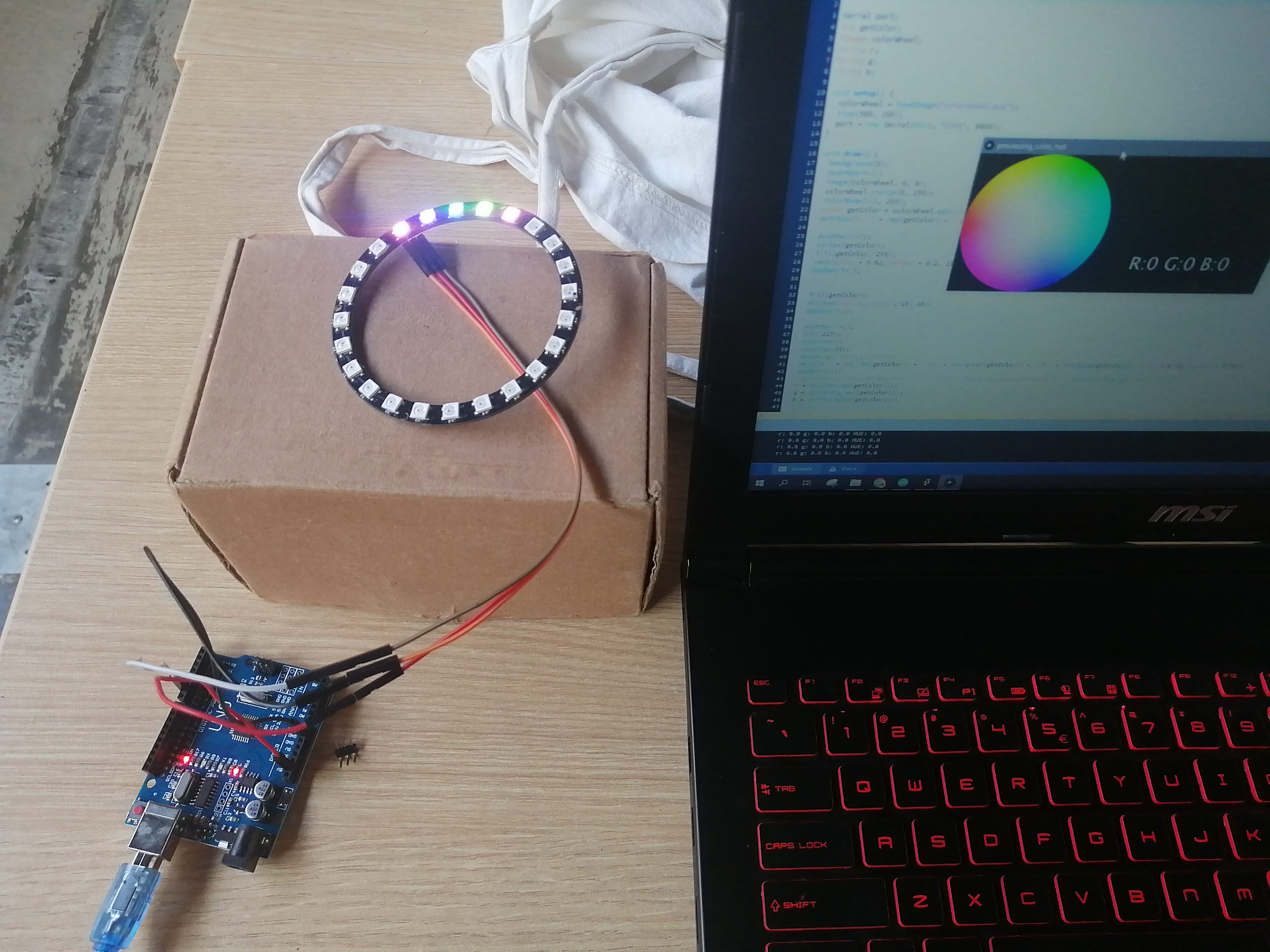
After some more adjustments to the Arduino code, I made all of the 24 pixels on the ring light up adding some definitions, but the colors were still all over the place.

Although the rainbow effect was nice, and the colors did change when the color wheel was clicked, I want to show a consistent RGB color. After trying changes in definitions, values, and even Baudrates, I noticed that the line:
Adafruit_Neopixel pixels(24, 6, NEO_GRBW + NEO_KHZ800),
On Arduino has maybe something to do with it, the NEO_GRBW corresponds to Green + Red + Blue +White values, but I noticed that my Neopixel ring has LED chips with only RGB, so I erased the W and reupload the Arduino code.
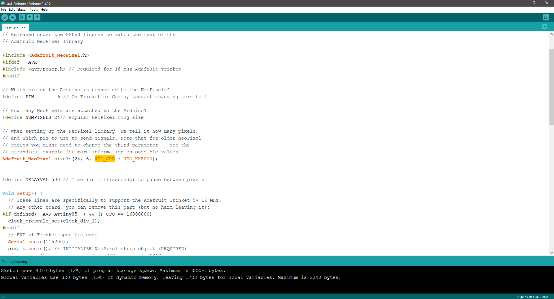
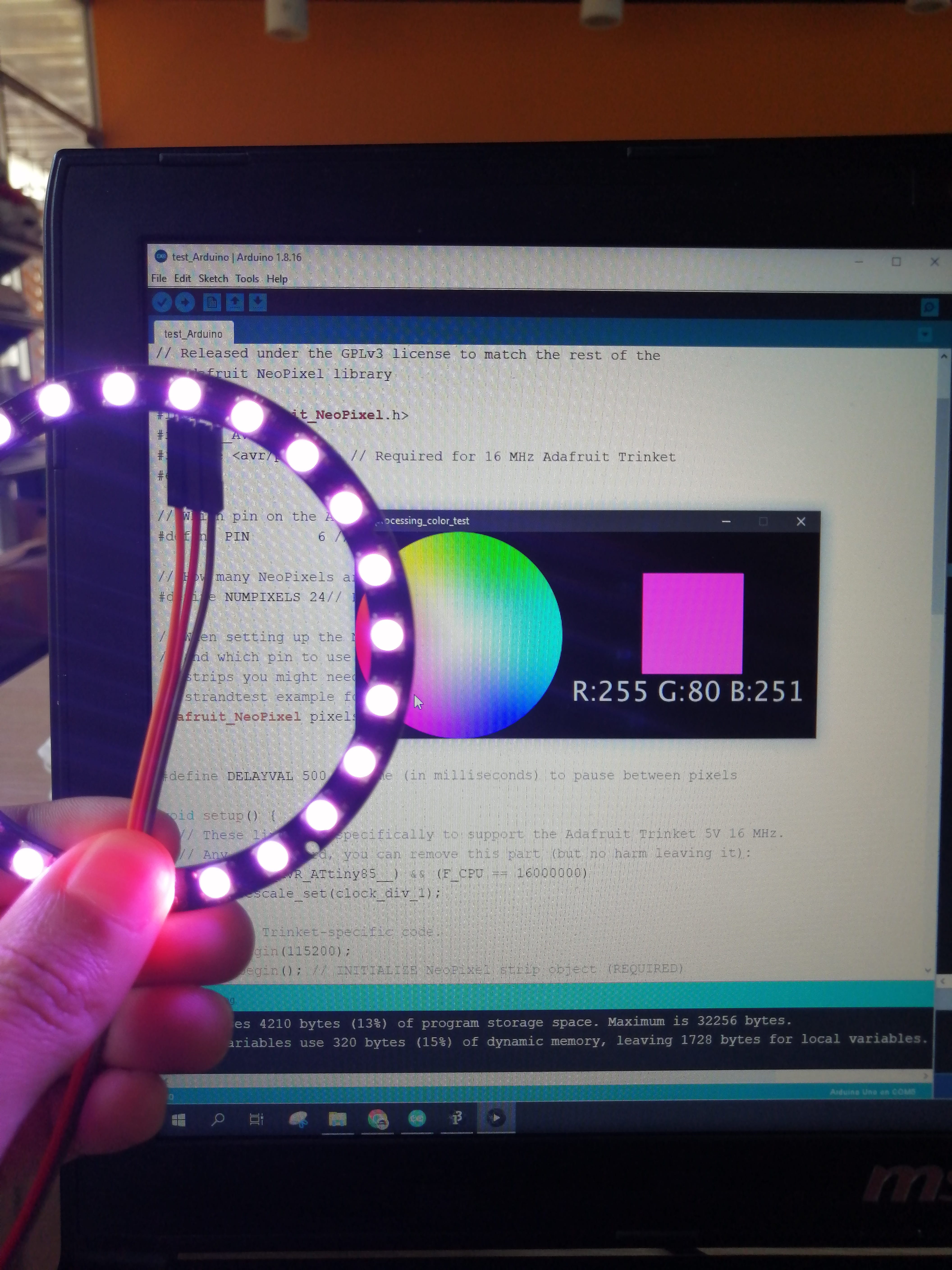
This made the Interface work as it should.
The Neopixel ring finally shows a consistent color every time the image is clicked.
My edited Arduino and Processing code:
Arduino Code
int i = 0;
char buf[20];
int color[24];

// NeoPixel Ring simple sketch (c) 2013 Shae Erisson
// Released under the GPLv3 license to match the rest of the
// Adafruit NeoPixel library

#include <Adafruit_NeoPixel.h>
#ifdef __AVR__
#include <avr/power.h> // Required for 16 MHz Adafruit Trinket
#endif

// Which pin on the Arduino is connected to the NeoPixels?
#define PIN        6 // On Trinket or Gemma, suggest changing this to 1

// How many NeoPixels are attached to the Arduino?
#define NUMPIXELS 24// Popular NeoPixel ring size

// When setting up the NeoPixel library, we tell it how many pixels,
// and which pin to use to send signals. Note that for older NeoPixel
// strips you might need to change the third parameter -- see the
// strandtest example for more information on possible values.
Adafruit_NeoPixel pixels(24, 6, NEO_GRB + NEO_KHZ800);


#define DELAYVAL 500 // Time (in milliseconds) to pause between pixels

void setup() {
  // These lines are specifically to support the Adafruit Trinket 5V 16 MHz.
  // Any other board, you can remove this part (but no harm leaving it):
#if defined(__AVR_ATtiny85__) && (F_CPU == 16000000)
  clock_prescale_set(clock_div_1);
#endif
  // END of Trinket-specific code.
  Serial.begin(115200);
  pixels.begin(); // INITIALIZE NeoPixel strip object (REQUIRED)
  pixels.show();            // Turn OFF all pixels ASAP
  pixels.setBrightness(50); // Set BRIGHTNESS to about 1/5 (max = 255)
}

void loop() {
  if (Serial.available()) {
    pixels.clear(); // Set all pixel colors to 'off'
    buf[i] = Serial.read();
    if (buf[i] == 'e') { // set 'e' at the end of the last caracter
      buf[i] = '\0';
      //Serial.println(buf);

      color[0] = atoi(strtok(buf, ","));
      color[1] = atoi(strtok(NULL, ",")); // use NULL from second group
      color[2] = atoi(strtok(NULL, ","));

      pixels.setPixelColor(0, color[0], color[1], color[2], 0);
      pixels.setPixelColor(1, color[0], color[1], color[2], 0);
      pixels.setPixelColor(2, color[0], color[1], color[2], 0);
      pixels.setPixelColor(3, color[0], color[1], color[2], 0);
      pixels.setPixelColor(4, color[0], color[1], color[2], 0);
      pixels.setPixelColor(5, color[0], color[1], color[2], 0);
      pixels.setPixelColor(6, color[0], color[1], color[2], 0);
      pixels.setPixelColor(7, color[0], color[1], color[2], 0);
      pixels.setPixelColor(8, color[0], color[1], color[2], 0);
      pixels.setPixelColor(9, color[0], color[1], color[2], 0);
      pixels.setPixelColor(10, color[0], color[1], color[2], 0);
      pixels.setPixelColor(11, color[0], color[1], color[2], 0);
      pixels.setPixelColor(12, color[0], color[1], color[2], 0);
      pixels.setPixelColor(13, color[0], color[1], color[2], 0);
      pixels.setPixelColor(14, color[0], color[1], color[2], 0);
      pixels.setPixelColor(15, color[0], color[1], color[2], 0);
      pixels.setPixelColor(16, color[0], color[1], color[2], 0);
      pixels.setPixelColor(17, color[0], color[1], color[2], 0);
      pixels.setPixelColor(18, color[0], color[1], color[2], 0);
      pixels.setPixelColor(19, color[0], color[1], color[2], 0);
      pixels.setPixelColor(20, color[0], color[1], color[2], 0);
      pixels.setPixelColor(21, color[0], color[1], color[2], 0);
      pixels.setPixelColor(22, color[0], color[1], color[2], 0);
      pixels.setPixelColor(23, color[0], color[1], color[2], 0);
      pixels.show();   // Send the updated pixel colors to the hardware.

      //send back data to processing
      Serial.println("color[0],color[1],color[2]");
//      Serial.println(color[1]);
//      Serial.println(color[2]);
      i = 0;
    }
    else {
      i++;
    }
  }
  }
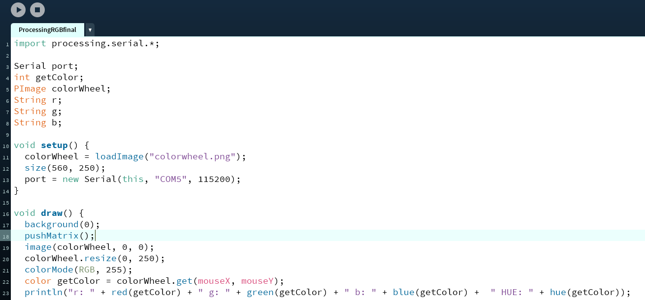
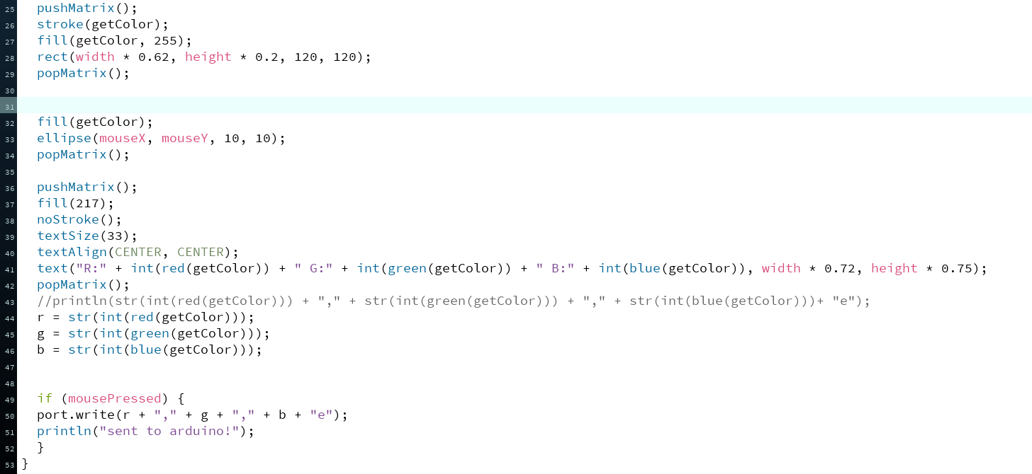
Processing code
import processing.serial.*;

Serial port;
int getColor;
PImage colorWheel;
String r;
String g;
String b;

void setup() {
  colorWheel = loadImage("colorwheel.png");
  size(560, 250);
  port = new Serial(this, "COM5", 115200);
}

void draw() {
  background(0);
  pushMatrix();
  image(colorWheel, 0, 0);
  colorWheel.resize(0, 250);
  colorMode(RGB, 255);
  color getColor = colorWheel.get(mouseX, mouseY);
  println("r: " + red(getColor) + " g: " + green(getColor) + " b: " + blue(getColor) +  " HUE: " + hue(getColor));

  pushMatrix();
  stroke(getColor);
  fill(getColor, 255);
  rect(width * 0.62, height * 0.2, 120, 120);
  popMatrix();


  fill(getColor);
  ellipse(mouseX, mouseY, 10, 10);
  popMatrix();

  pushMatrix();
  fill(217);
  noStroke();
  textSize(33);
  textAlign(CENTER, CENTER);
  text("R:" + int(red(getColor)) + " G:" + int(green(getColor)) + " B:" + int(blue(getColor)), width * 0.72, height * 0.75);
  popMatrix();
  //println(str(int(red(getColor))) + "," + str(int(green(getColor))) + "," + str(int(blue(getColor)))+ "e");
  r = str(int(red(getColor)));
  g = str(int(green(getColor)));
  b = str(int(blue(getColor)));


  if (mousePressed) {
  port.write(r + "," + g + "," + b + "e");
  println("sent to arduino!");
  }
}
Time to see the beautiful colors!
Group Assignment
For the group assignment, we tested MITApp inventor and Processing. This group task is docummented also on my classmate’s FabAcademy page, Lesly Ramirez.
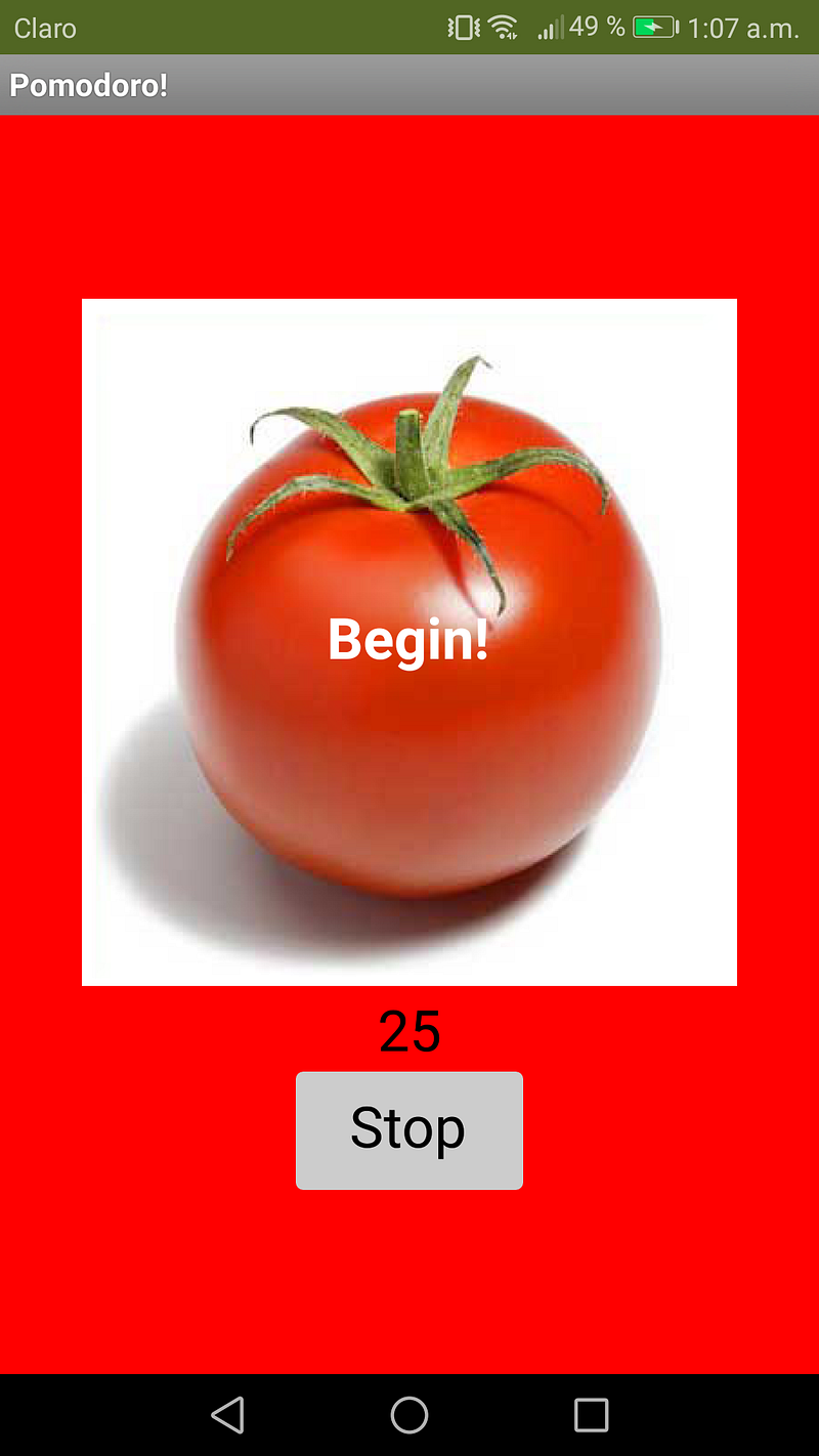
Bonus: Pomodoro APP
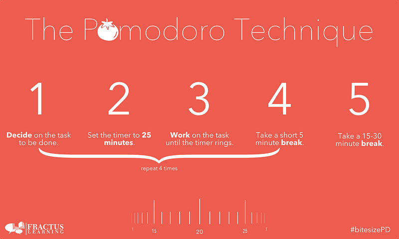
As I got distracted very easily I made a simple app to test the Pomodoro technique: 25 minutes of work, 5 minutes of break, and a long break of half an hour every 4 cycles.
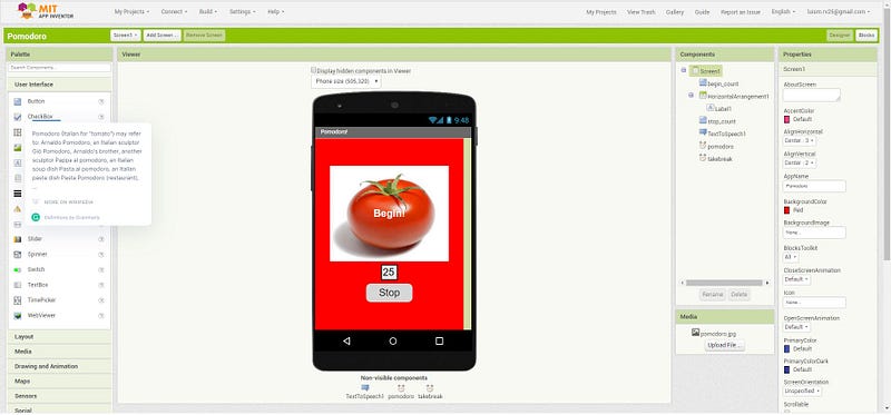
Here’s a view of the app design and a screenshot. The number set to 25 is a timer, it starts counting backward as you press the Pomodoro it shouts GET TO WORK!, when the count reaches 0 the app will shout TAKE 5 MINUTES! and then reset the count to 25 minutes.
You can download and try the Pomodoro app yourself here:
Note that this download is on .aia format (to be open with MIT App Inventor), so feel free to explore and edit the blocks.