This week’s assignment is to measure the power consumption of an output device and to add an output device to a microcontroller board you’ve designed and program it to do something.
Selected output devices
I’ll be working on the primary output devices for my final project, an RGB Neopixel ring to show by color code the reading taken by the pulse sensor as shown in Input devices and an MG 996R Servomotor to make the pulsating movement.
As I used the Neopixel ring on Embedded Programming week, now I’ll be working mainly with the Servo.
This is the Tower Pro MG 996R HI TORQUE Digital Servo
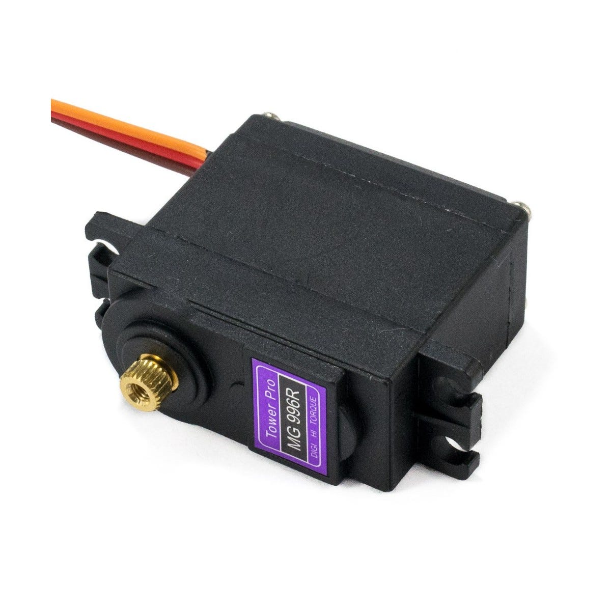
This Digital Servo features metal gearing resulting in extra high 10kg stalling torque in a tiny package. The MG996R features upgraded shock-proofing and a redesigned PCB and IC control system that make it much more accurate than its predecessor.
The gearing and motor have also been upgraded to improve dead bandwidth and centering. The unit comes with 3 pins ‘S’ type female header connector that fits most receivers. This high-torque standard servo can rotate approximately 120 degrees (60 in each direction). You can use any servo code, hardware, or library to control these servos.
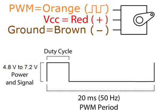
According to the Datasheet, its operating voltage goes from 4.8v to7.2v
Programming the Servo
I Already worked with this servo in the Mechanical and machine design assignment, so I’ll be using a modified version of the code to test the output. In the previous assignment, the servo moved from 0 to 180 and back using a potentiometer as a switch.
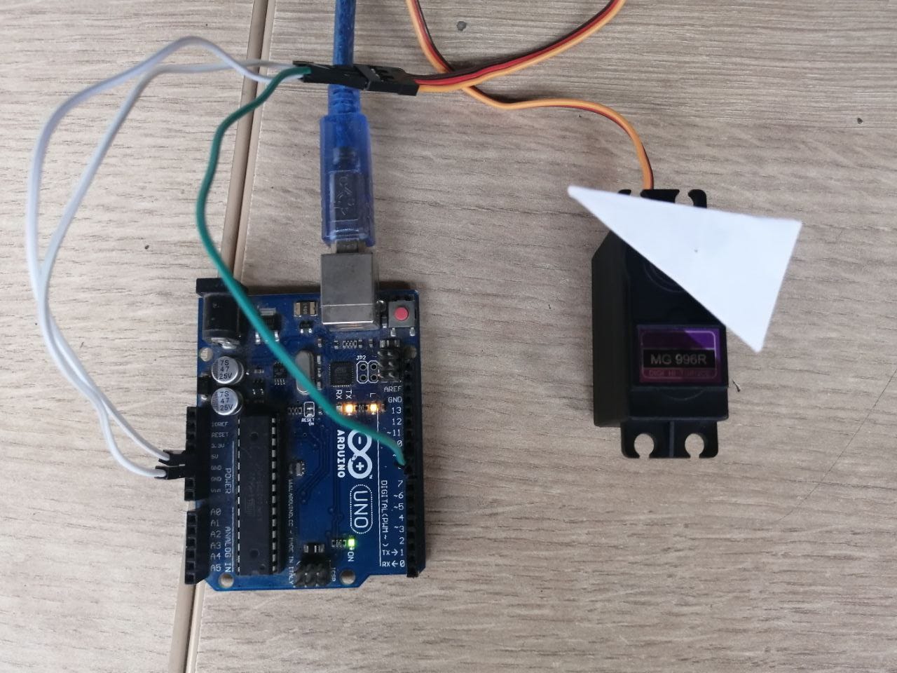
I tested this code first with the Arduino UNO to see the servo movement, I simplified the code by erasing the potentiometer part.
#include <Servo.h>

long valor;

// Declaramos la variable para controlar el servo
Servo servoMotor;

void setup() {

// Iniciamos el monitor serie para mostrar el resultado
  Serial.begin(9600);

// Iniciamos el servo para que empiece a trabajar con el pin 9
  servoMotor.attach(9);
}

void loop() {

// Desplazamos a la posición 0º
  servoMotor.write(0);
  delay(2000);

  servoMotor.write(180);
  delay(2000);

}
It is important to use the ServoMotor.attach to assign a PWM pin, in this case, I am working with pin 9. This is the basic setup. I attached a paper arrow to the gear to see the movement.
Here is a short video of the movement, we can notice the inertia moving the servo itself as it stops.
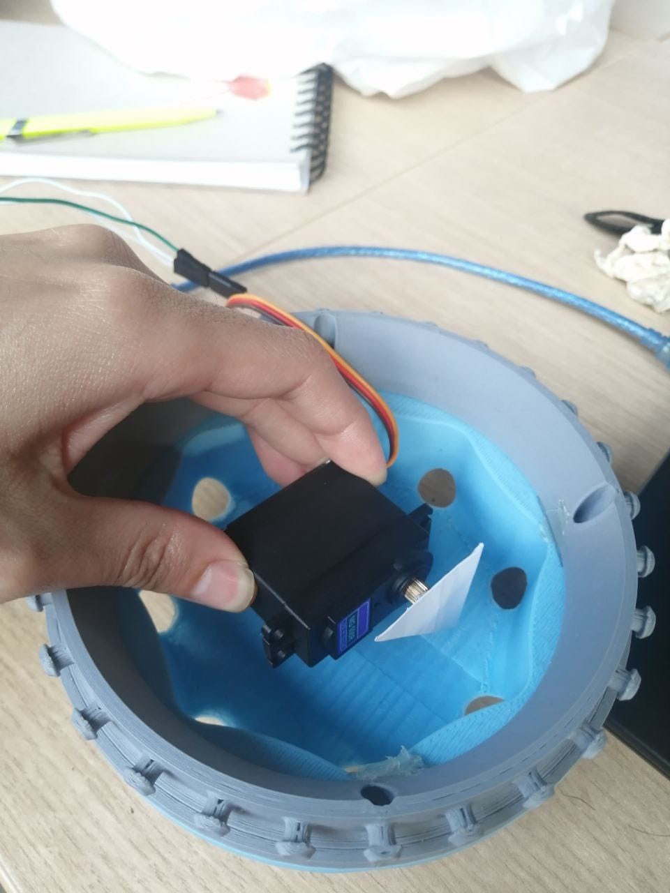
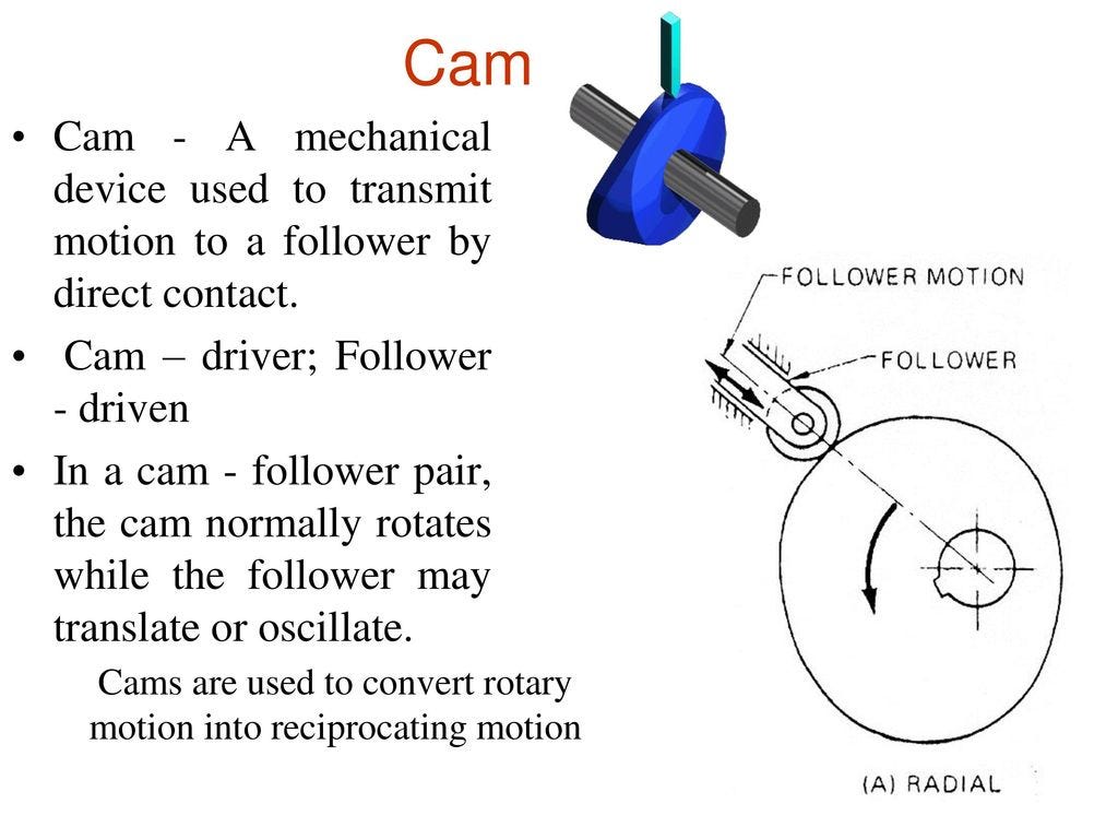
The idea for the setup in the final project is to place the servo in a central position (as it is heavy) in the base, attached to the servo gear will be a Cam and follower mechanism to move a base up and down to replicate a pulsating movement.
Testing the Servo with the Octoduino
To upload the code to the Octoduino I used the same procedure explained in Embedded programming and Input devices using my FabISP. I needed to check first what PWM pins I had available in the Octoduino (check the pinout here).
Looks like the Atmega328P pin 9 has PMW but this corresponds to Arduino pin 5 so we need to change this on the code.
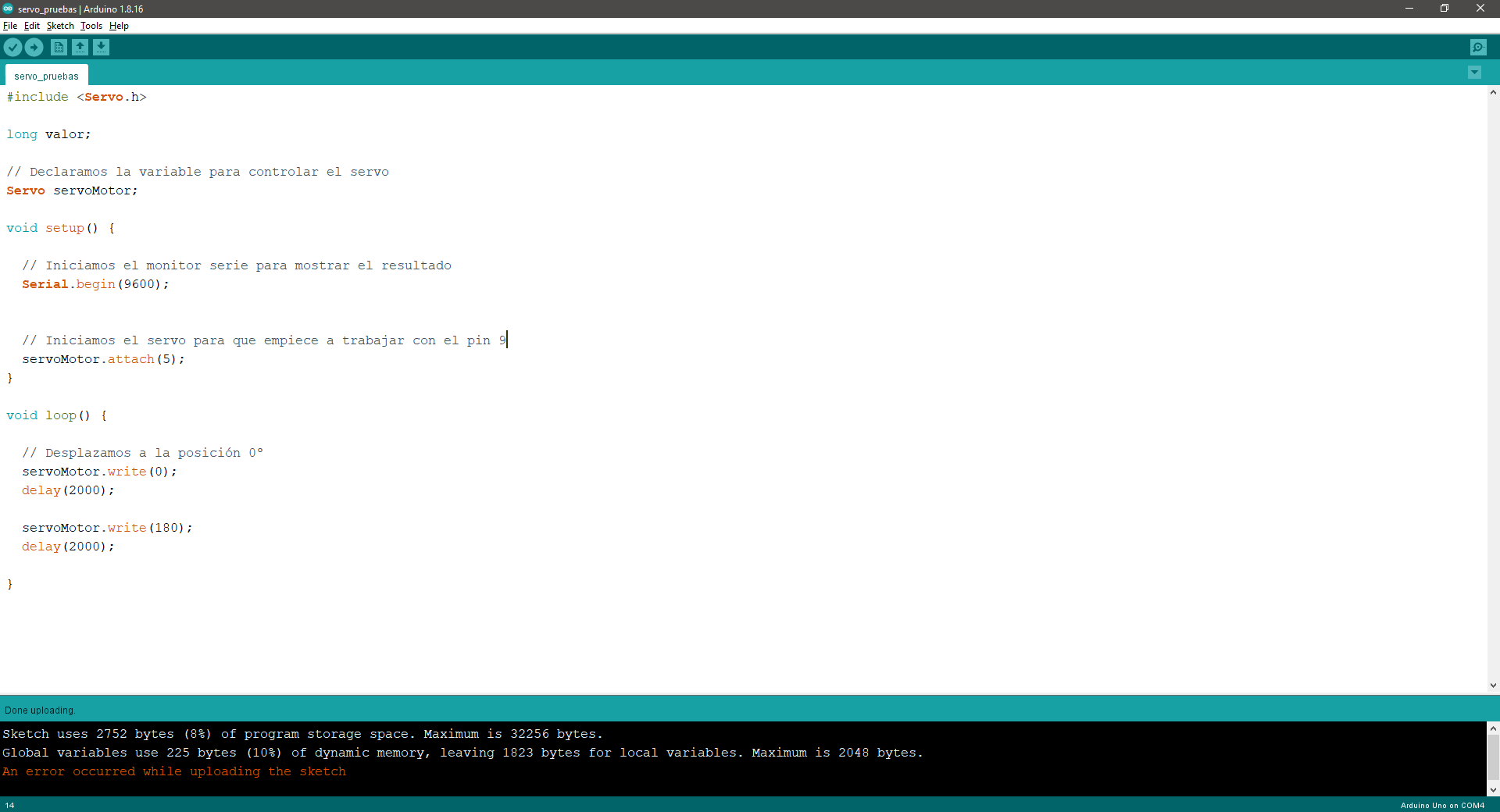
Oddly enough the upload showed an error message afterward, but it seemed to work OK! this is the Octoduino Setup
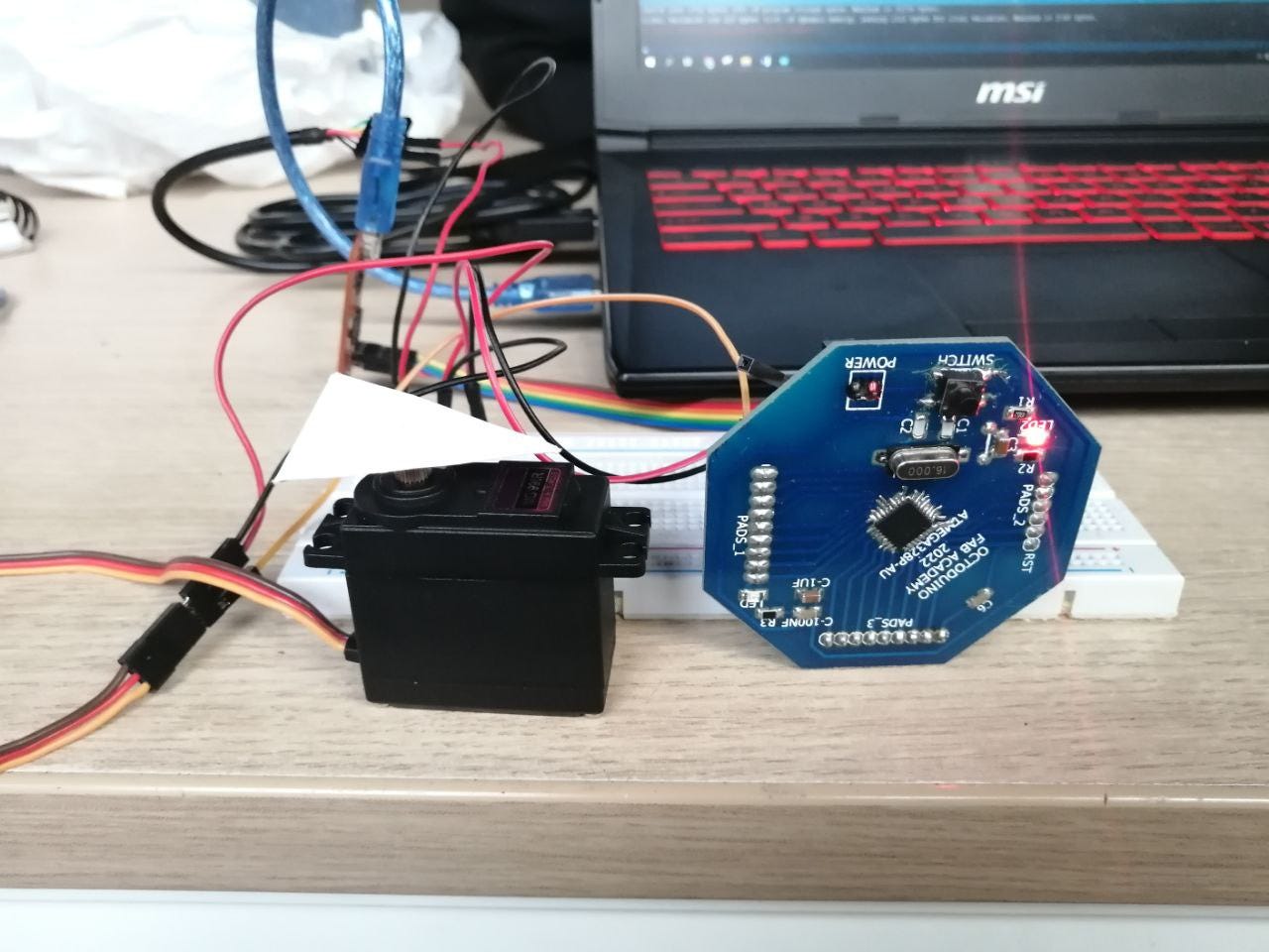
And this is the movement produced
Group assignment: Measure the power consumption
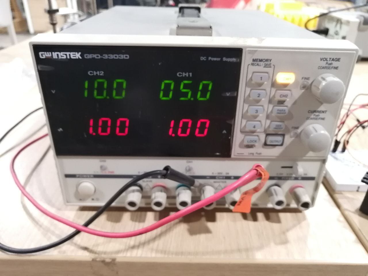
To measure the power consumption, I used the DC Power Supply GW Instek GPD-3303, you can see more detail in the following link.
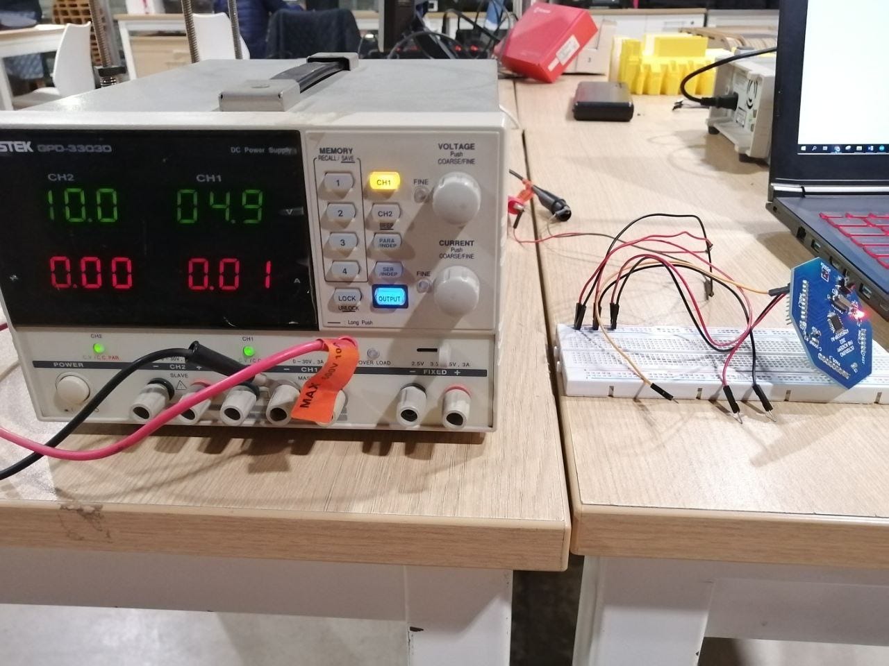
I configured the Voltage to 5V and 1A to check the power consumption of the Octoduino board alone. The result is 4.9V and 0.01A
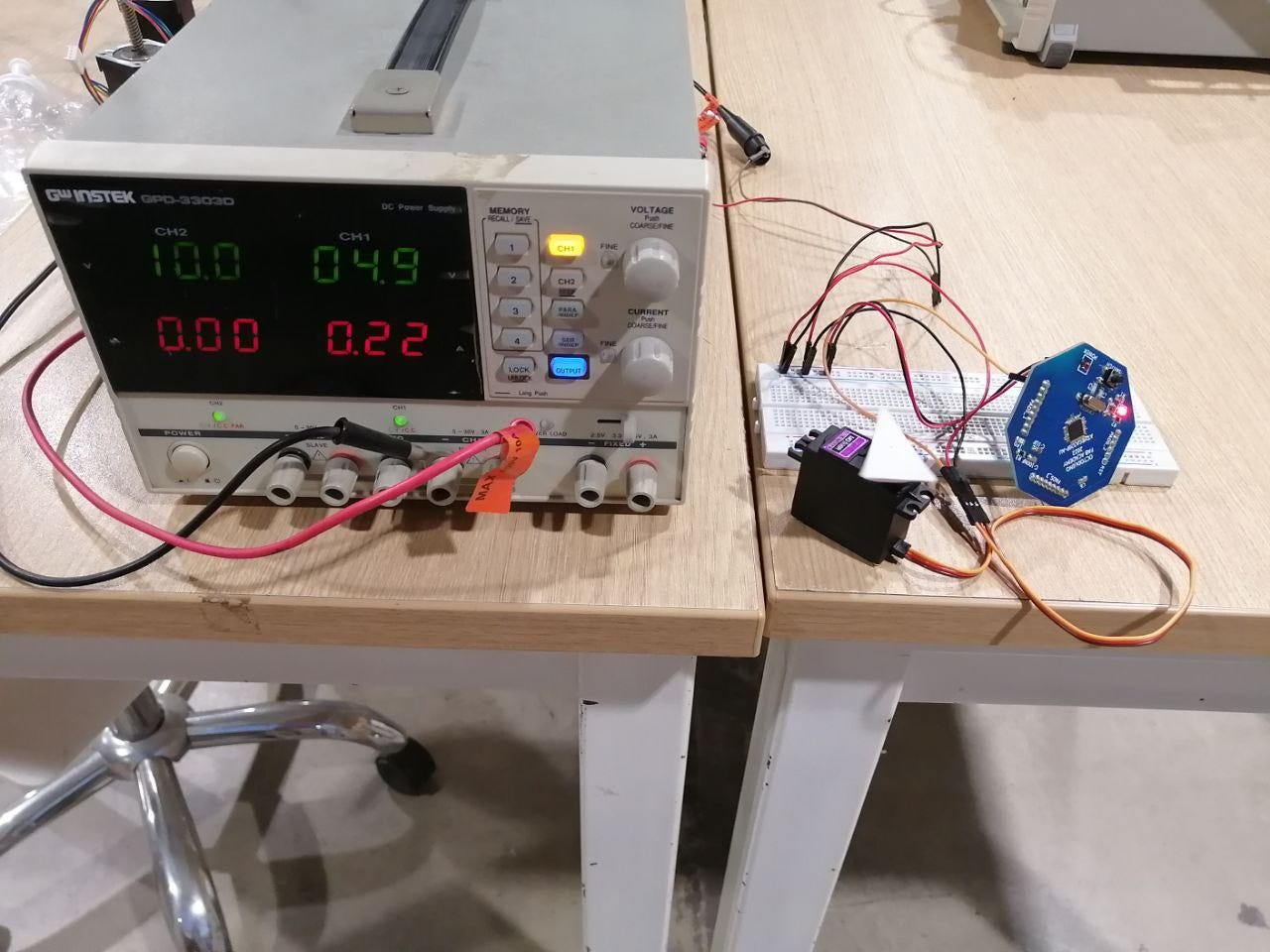
Next, I plugged the Servo, I did not change the voltage or amp settings, The voltage remain stable at 4.9v but the amp peak from 0.35A at the start of the movement to 0.15A in continuous movement to 0.02A when the servo is still. So I can conclude that the power consumption of the servo is around 0.14A and 0.7W.
With both loads: Octoduino + Servo
Power consumption resume:
POWER SETTINGS:

P = 5V x 1A

P =  5W

WITH LOAD(OCTODUINO):
P = 4.9V x 0.01A
P = 0.05W

WITH LOAD(OCTODUINO + SERVO):
P = 4.9V x 0.15A
P = 0.75W
Checking the power consumption:
Electronic boards
Download the Octoduino Board used in this assignment.