The assignment goals
This week’s assignment is to design, build, and connect wired or wireless node(s) with network or bus addresses, and as a group assignment, to send a message between two projects.
I decided to make a wired connection between a BRIDGE and NODES using Neil’s hello.bus.45 with the Attiny45.
Individual assignment
Design
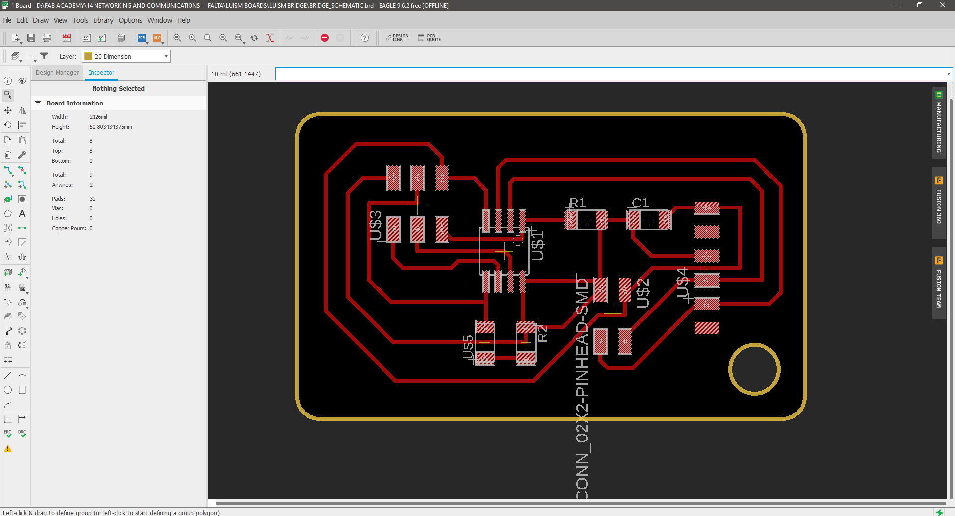
I Edited Neil’s Bridge and Node board designs following the workflow explained in the Electronics design assignment and using my fab lab mate Lesly as a design reference.
Here is the hello.bus.45 **original boards: hello.bus.45.bridge traces, and interior hello.bus.45.node traces, and interior
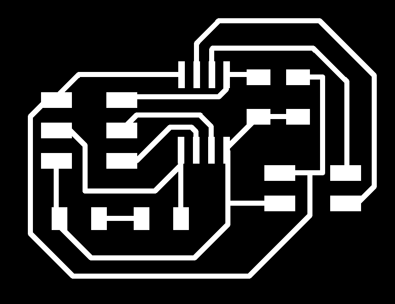
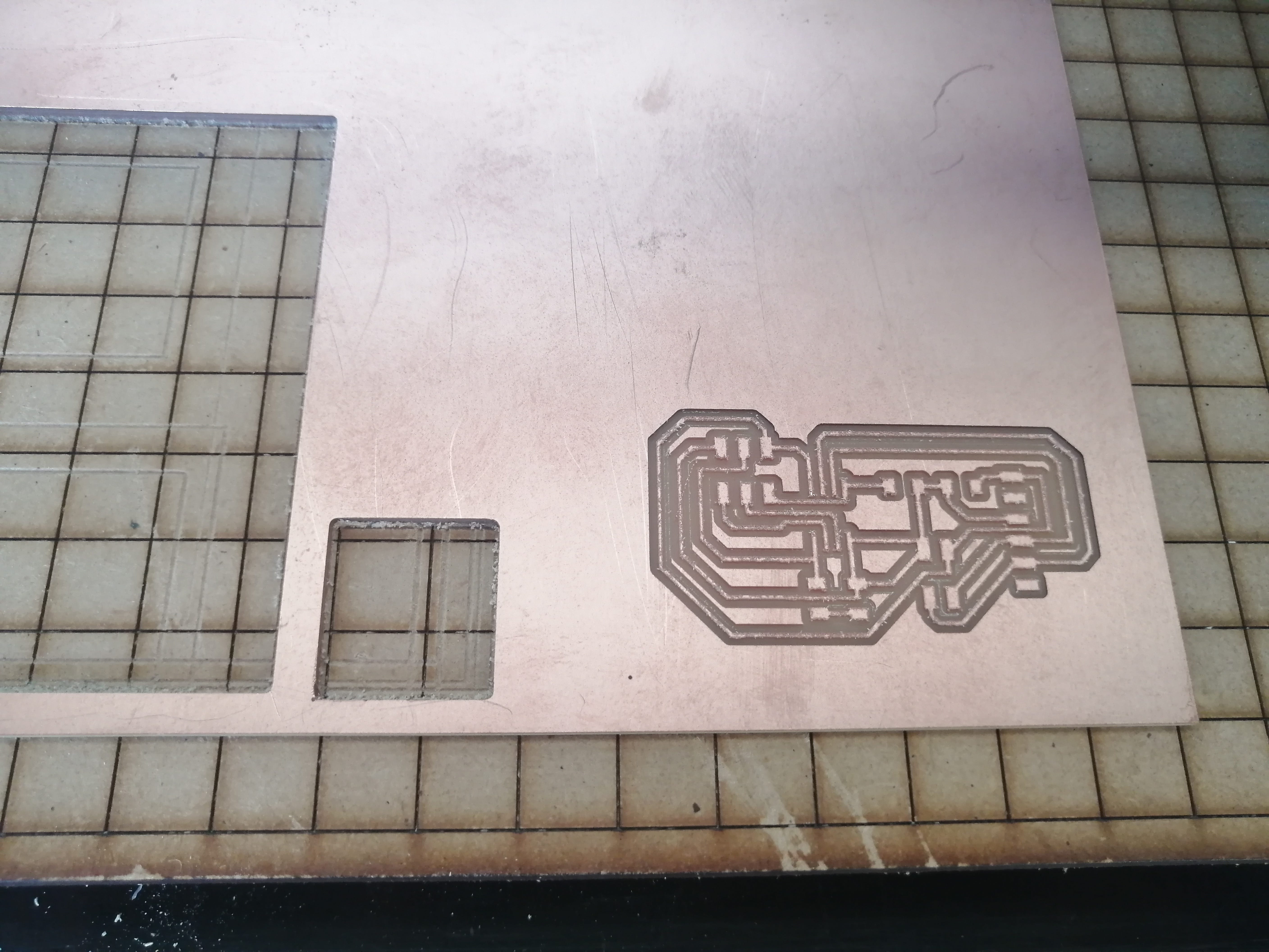
After completing the schematic and board design for both boards I exported them as .png images to mill in the Roland Modela.
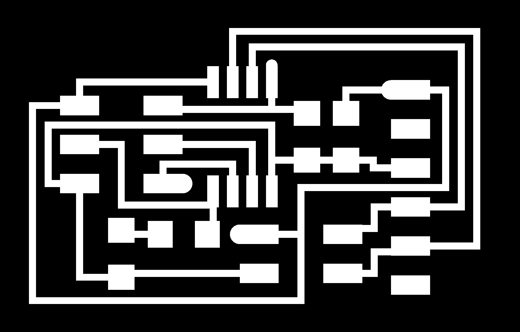
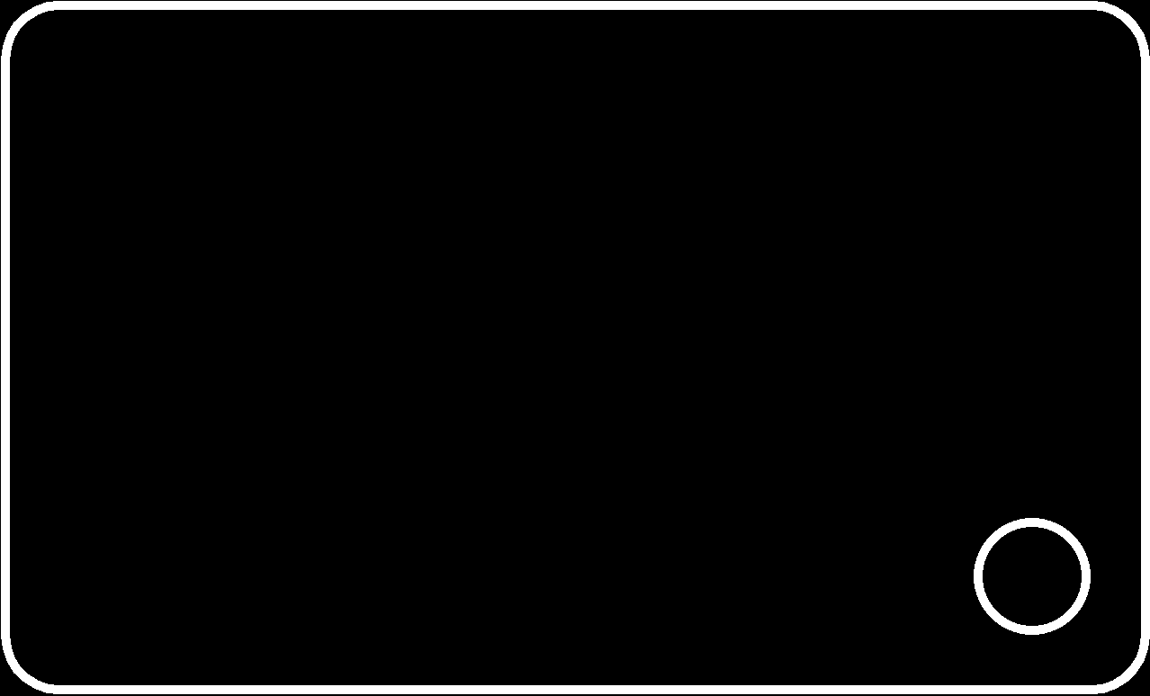
This is the OUTLINE and TRACES image for the BRIDGE BOARD

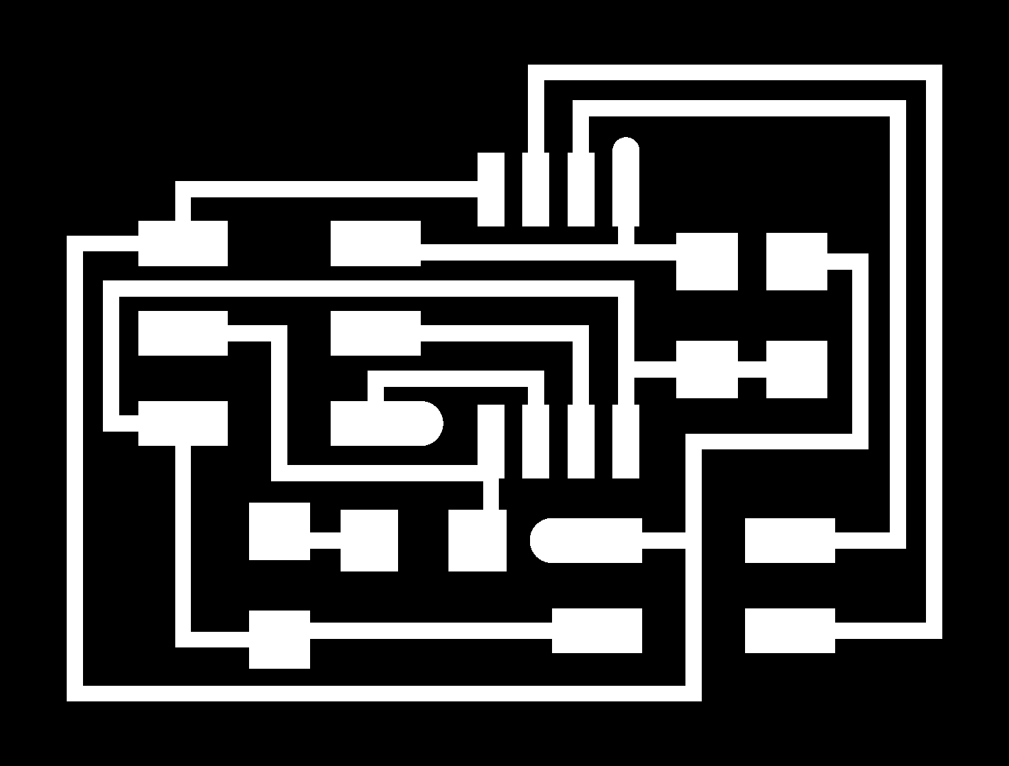
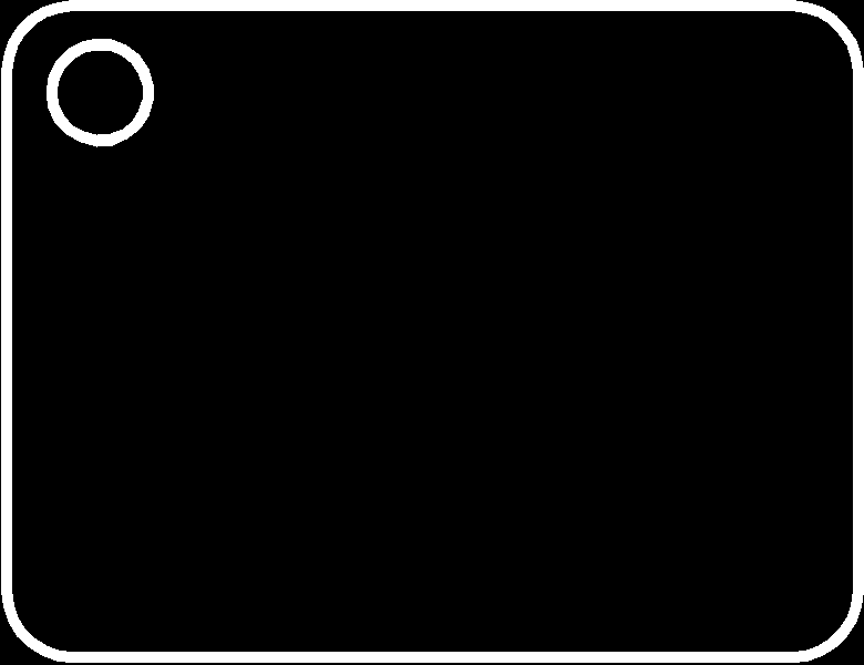
This is the OUTLINE and TRACES image for the NODE BOARD, I’ll need two nodes for the communication.
Build
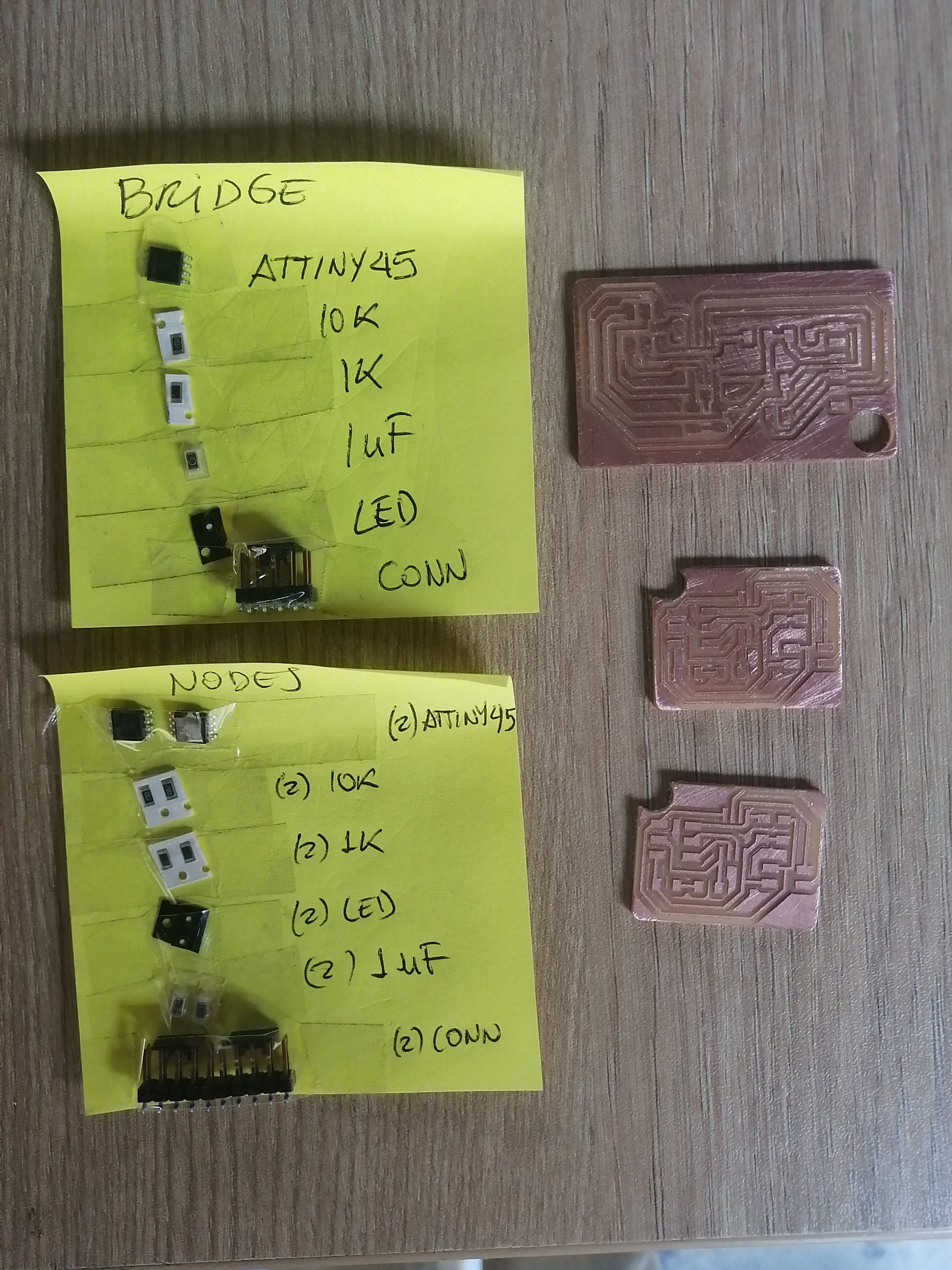
The Bridge and Node board designs are fabricated following the workflow explained in the Electronics production assignment and using Fablab’s Roland Modela MDX-20.
The fabrication process went uneventful and an hour or so later I had the board ready to be stuffed. The components list is the same as Neil’s original design.
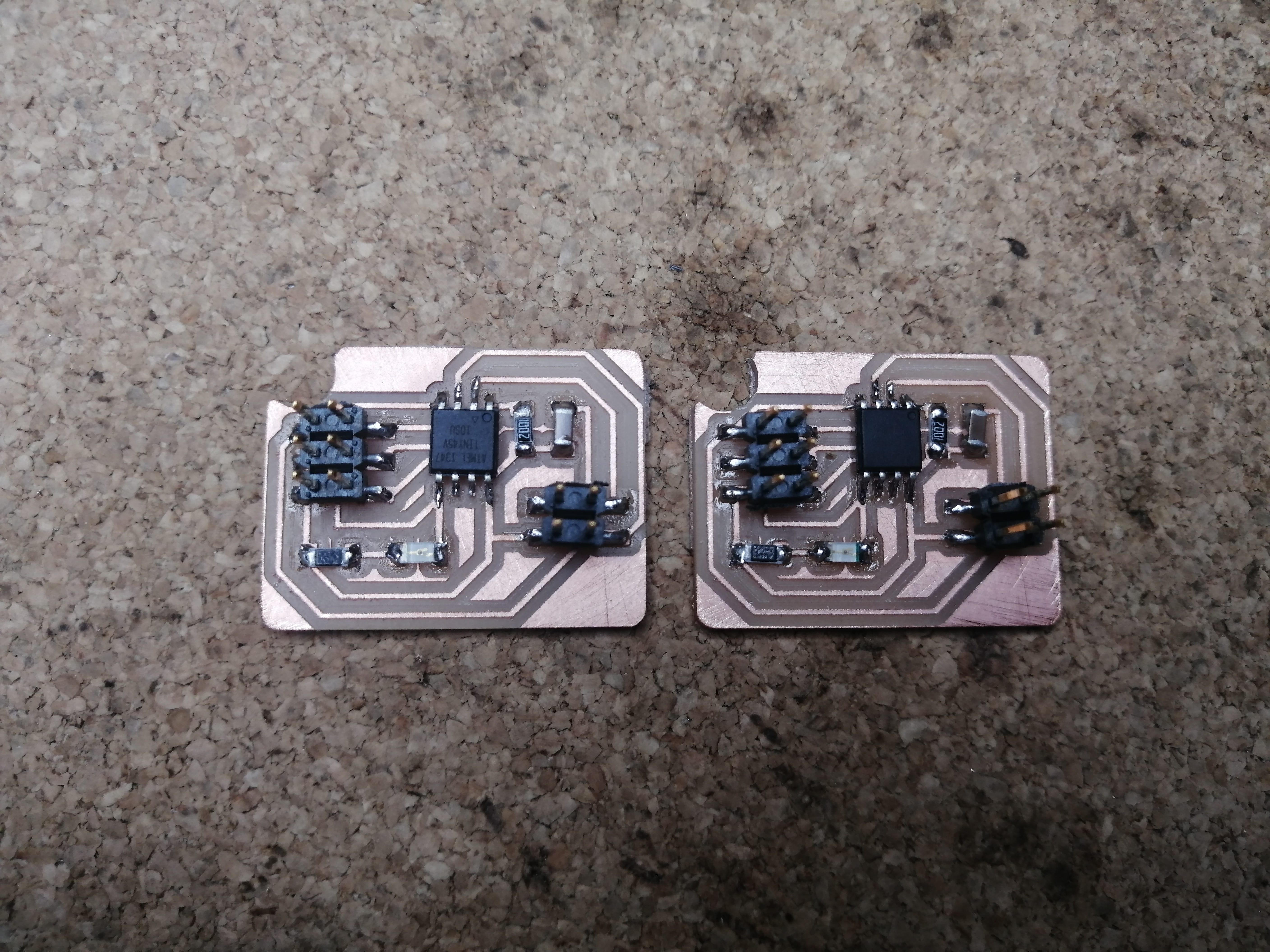
It was a long time since I hadn't soldered components, and I find it quite relaxing, so I took my time stuffing the boards. This is the BRIDGE board:

And the NODEs:
Programming and testing
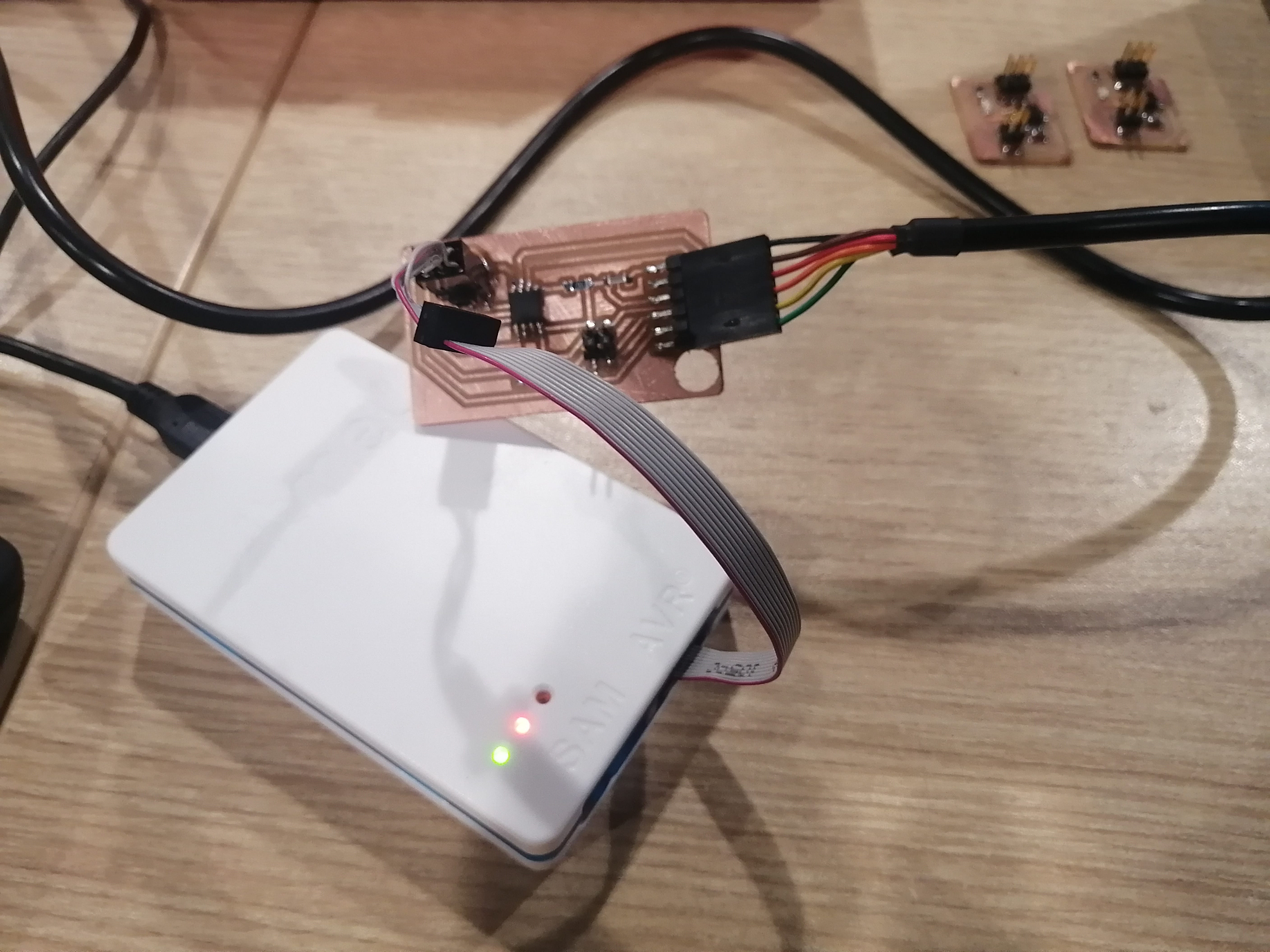
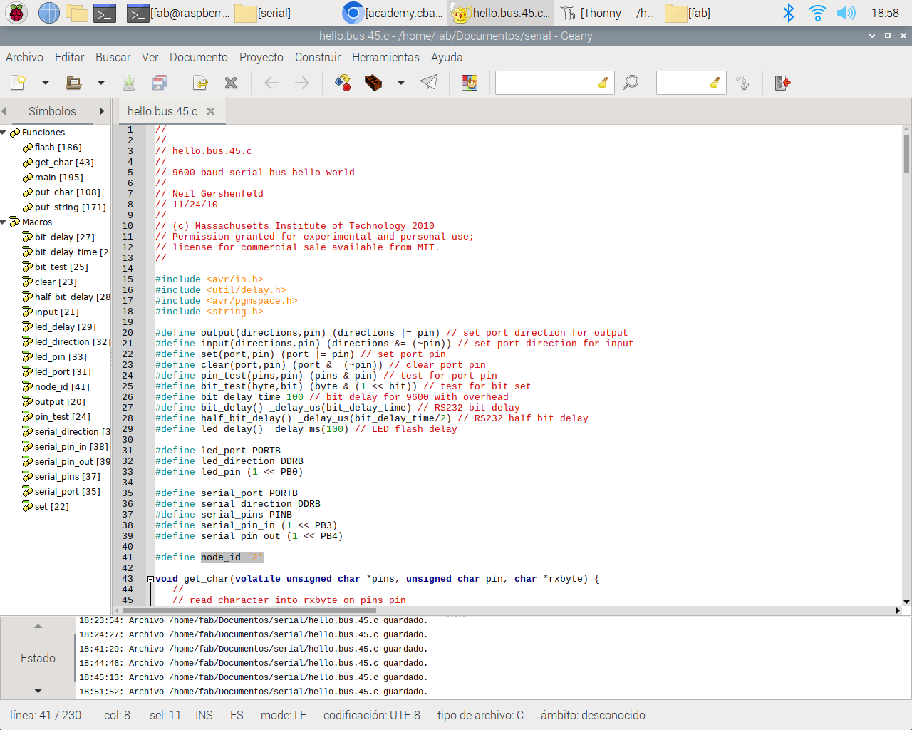
The first step is to program the bridge and node boards, this is made with the code available in hello.bus.45.c and the makefile. To boot the code in the bridge board I used the Atmel ICE programmer and an FTDI cable.
The code is the same for all the boards, I just needed to edit the node_id tag for each, being 0 for the Bridge, and 1 and 2 for the Nodes.
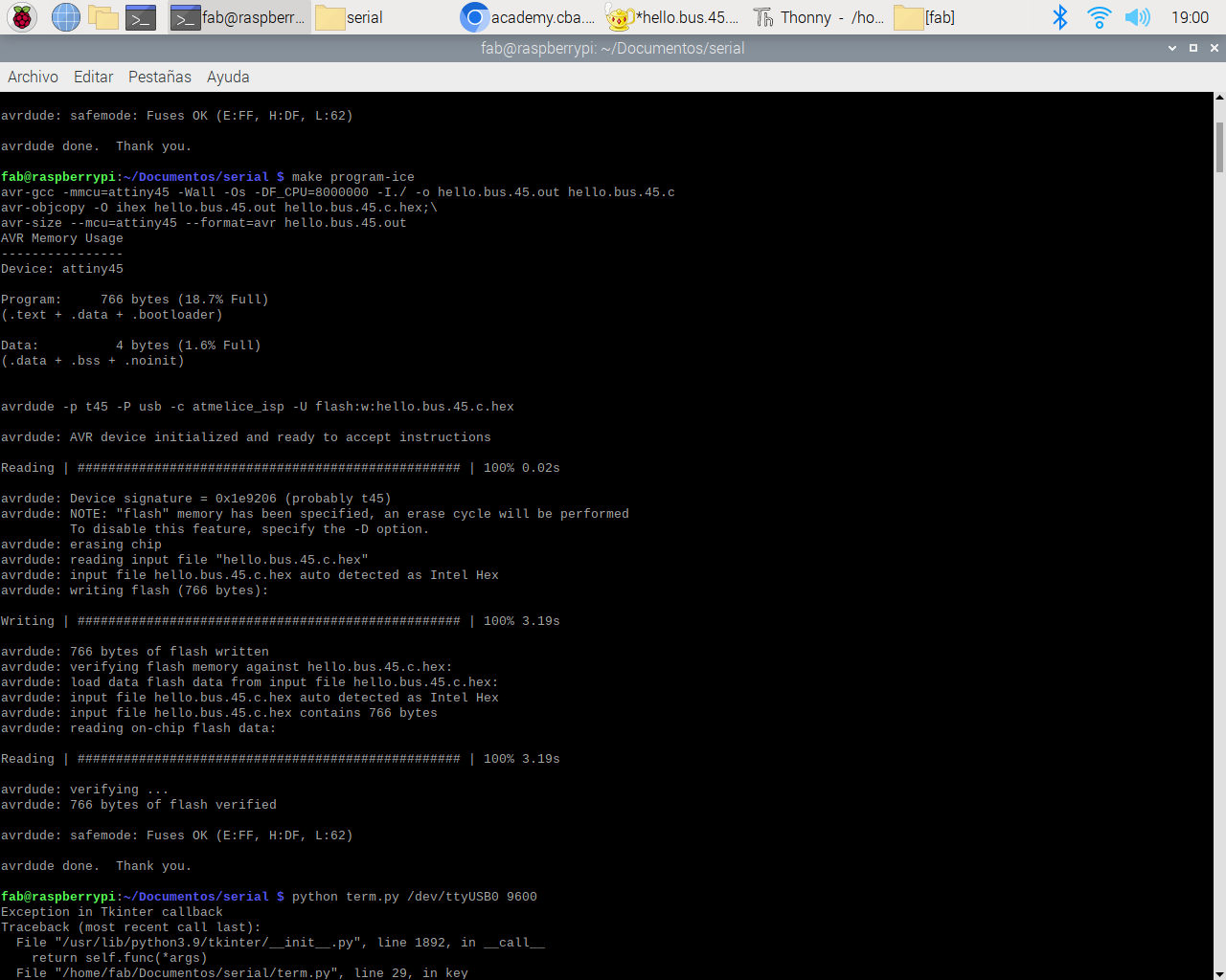
To boot the code I used the command: make program-ice. The booting went well with all of the boards, it's always good to see the Avrdude done. thank you in the console.
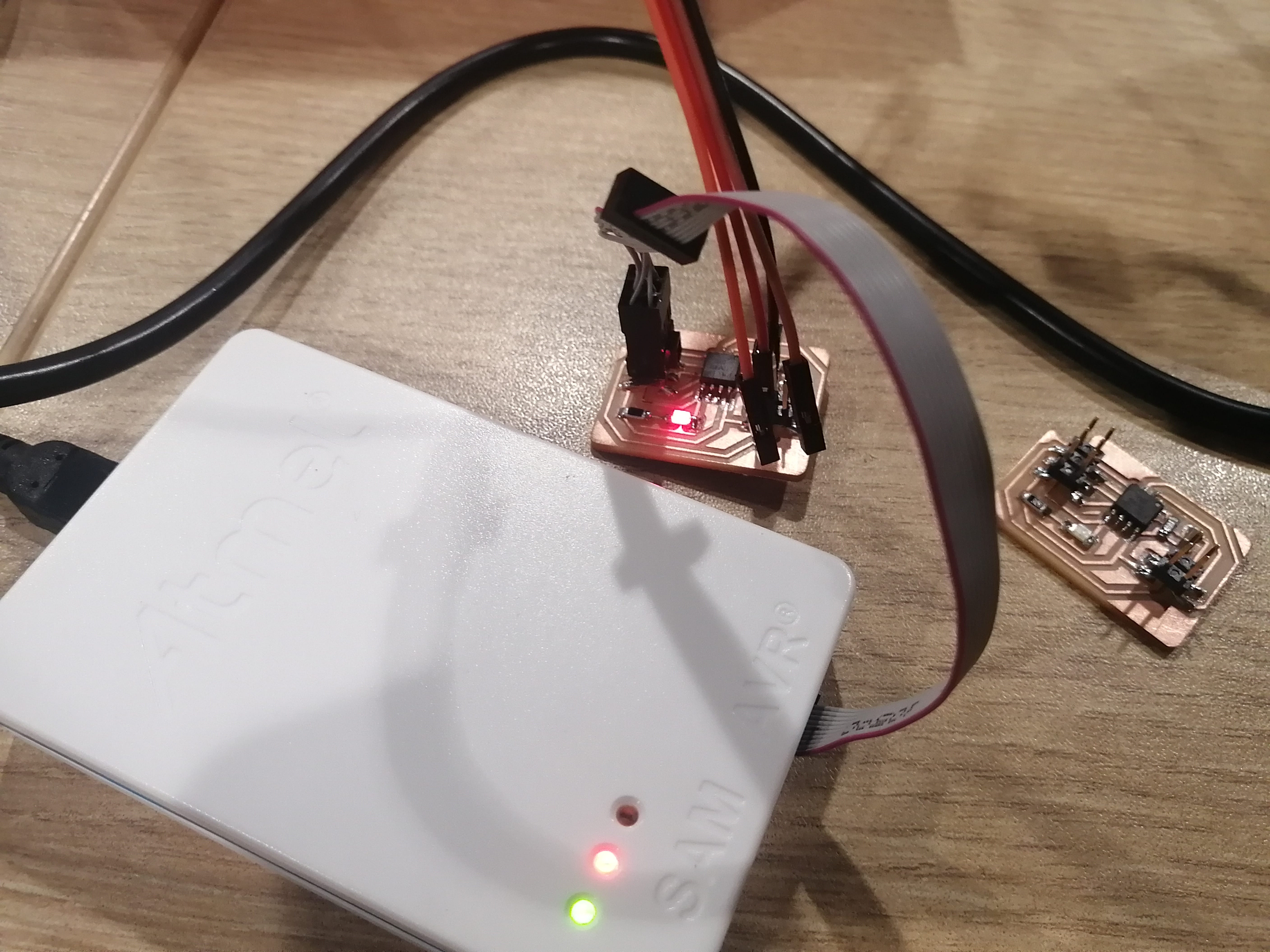
Here is one of the Nodes being programmed.
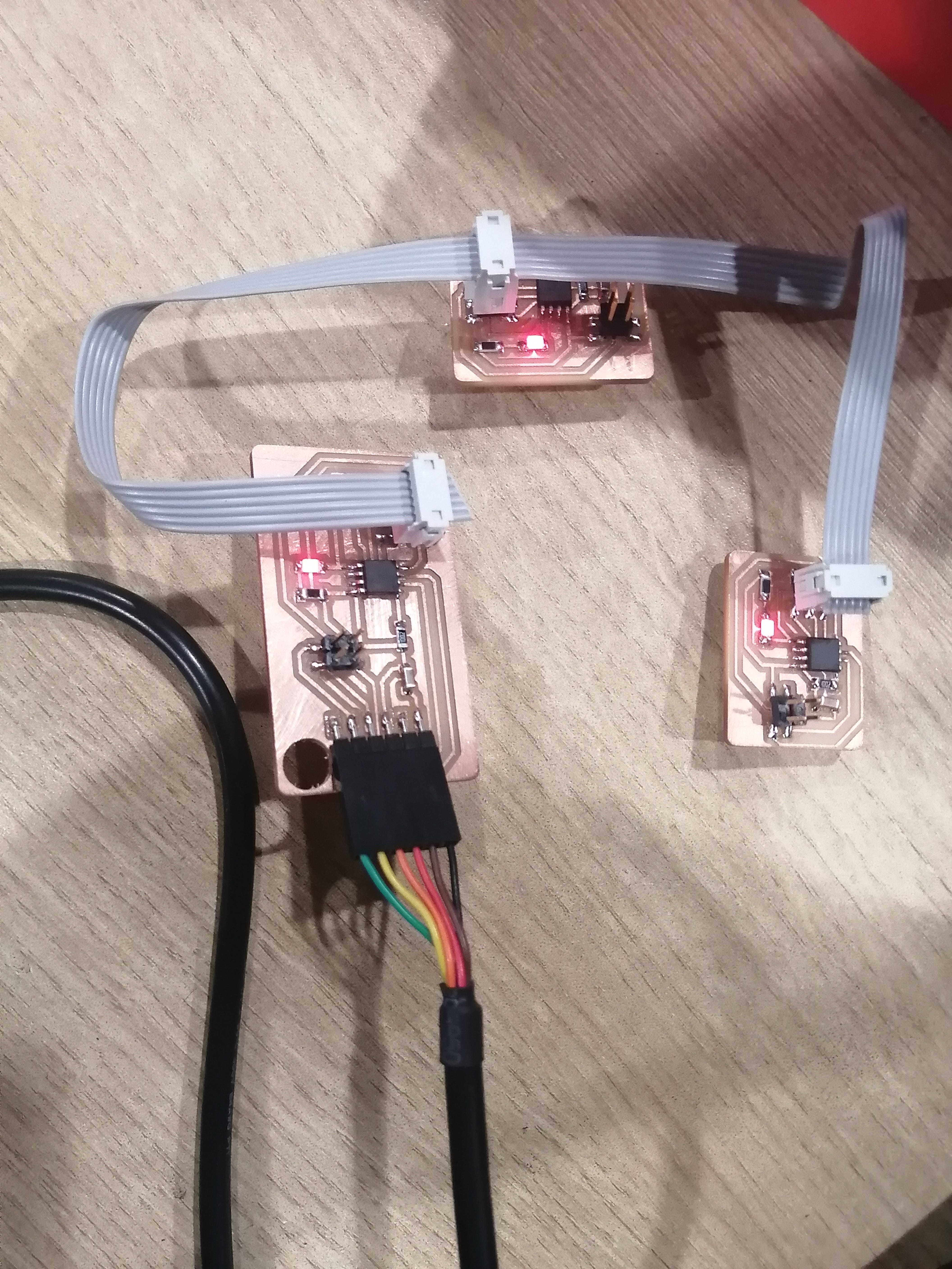
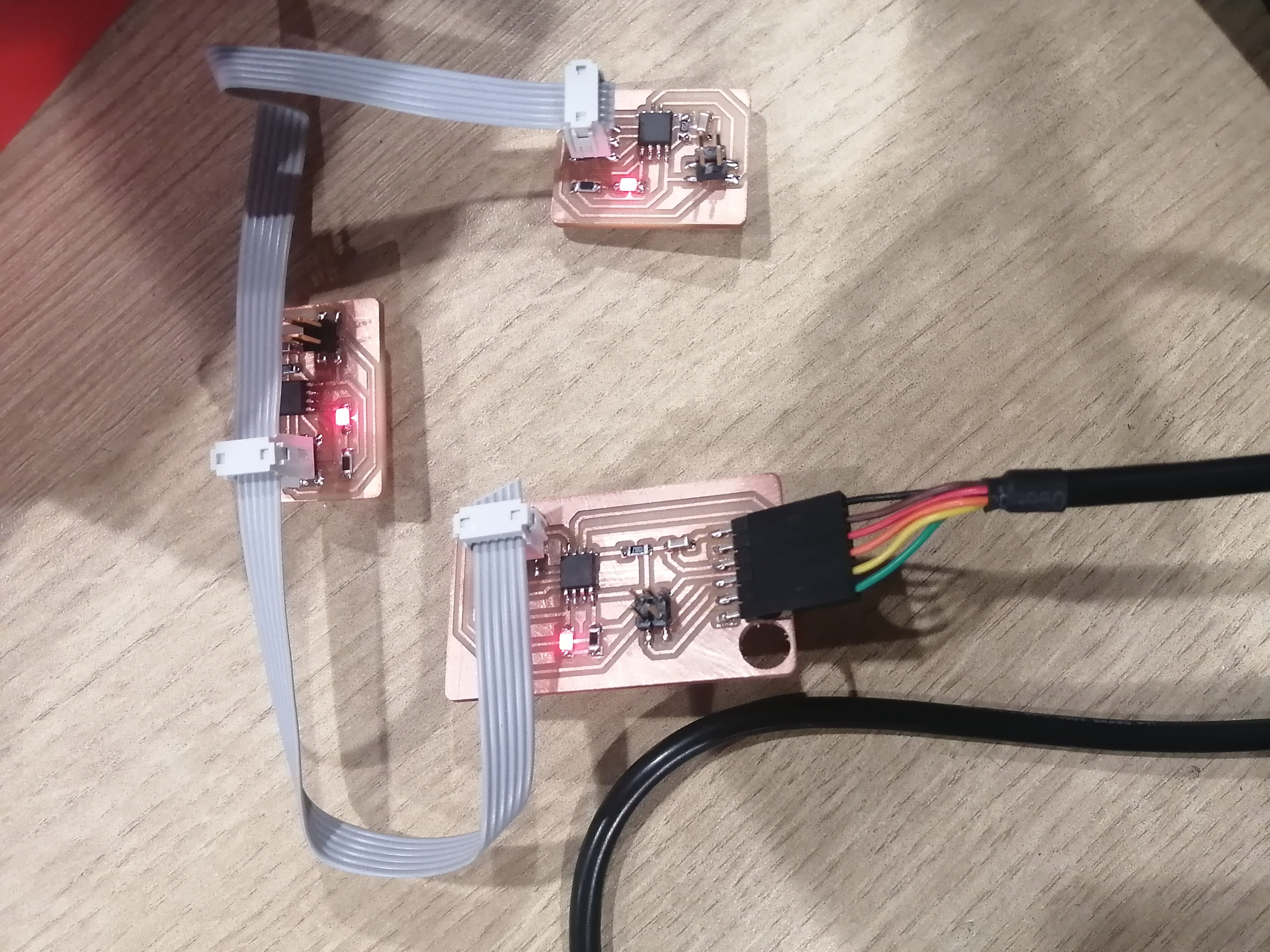
Now that all the boards are programmed, it's time to test the communication, With the instructor's help we set up a ribbon cable connection for the Bridge and Nodes. All the boards had the LEDs and seem to work ok, but it was not…
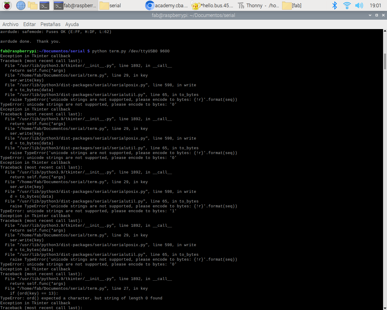
I tried to test the Py console from the Linux terminal (the same one used for the programming) but I kept getting errors.
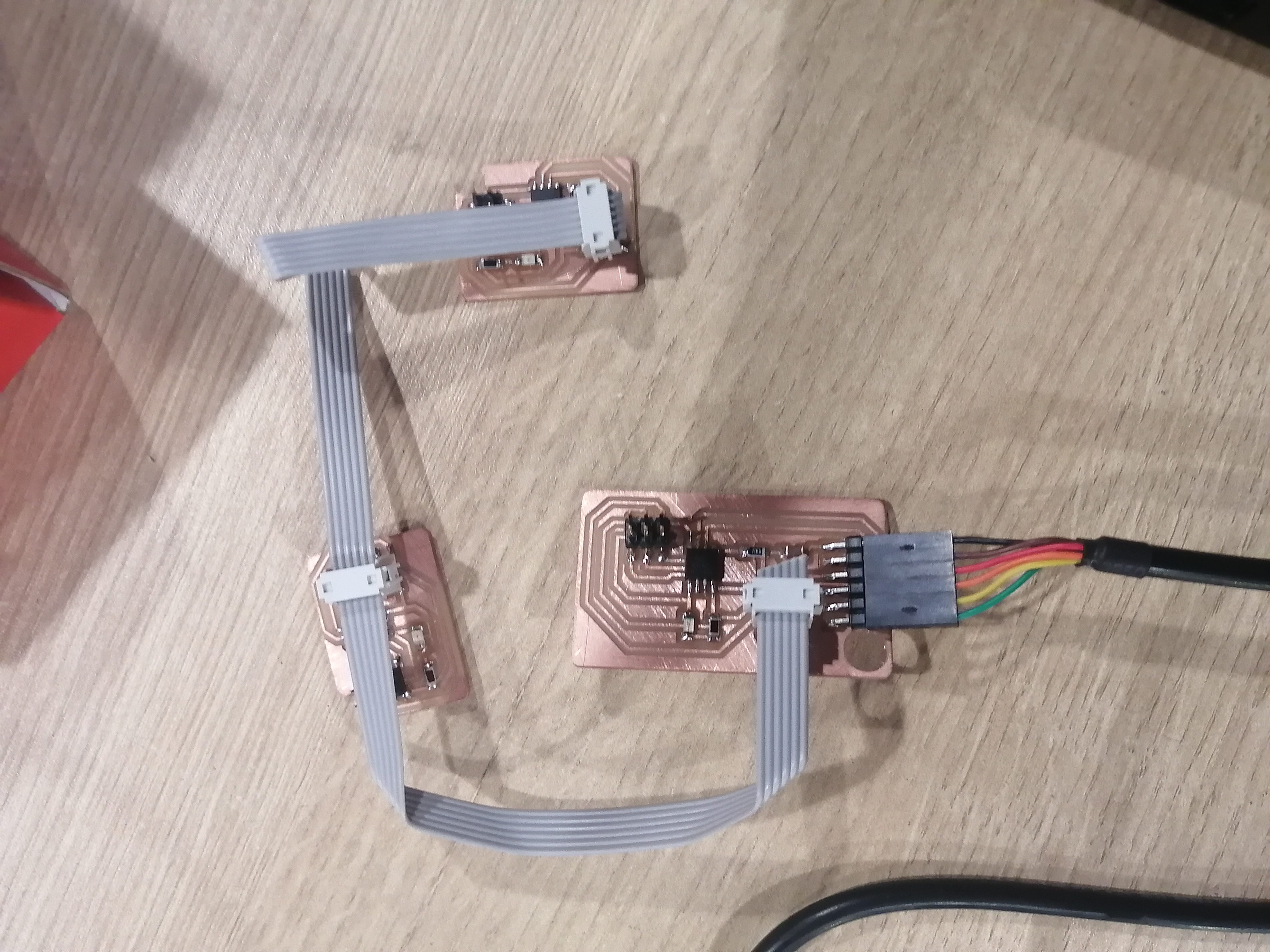
I changed to a PC and Arduino IDE to use the Serial monitor, but still, not a consistent response from the nodes, only Node 0 (Bridge) was responding. Upon closer inspection, the error came from a connection misplacement. I connected the ribbon cable to de 3x2 connector, but the bus should use the 2x2 and the Tx — Rx pins.
Did you notice the change? Also, we programmed the Nodes again to make the LED off by default and only blink when called, this is made by commenting the //flash line in the original code.
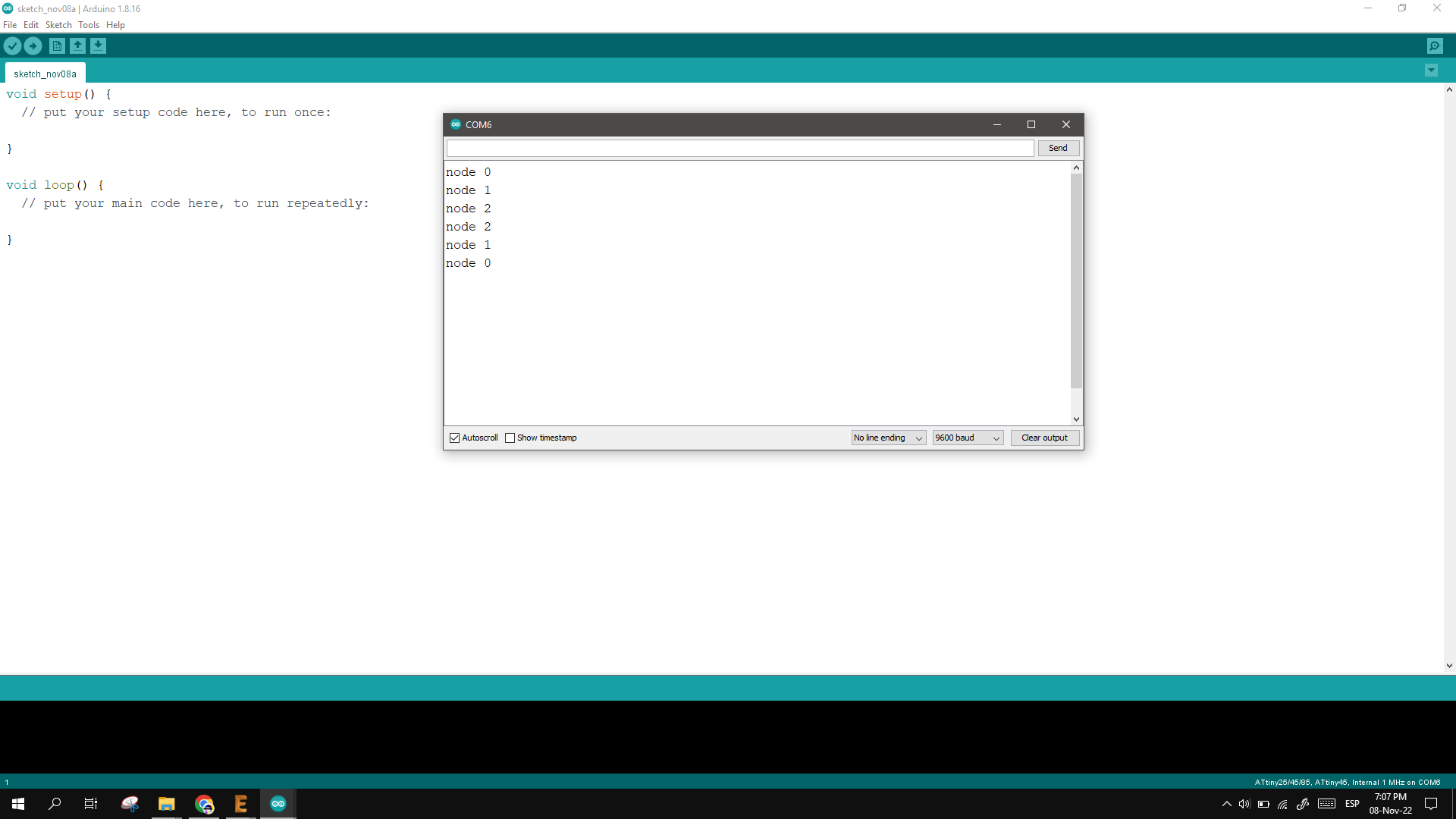
From Arduino IDE we changed the board to Attiny and select the COM port to match the FTDI, open the Serial Monitor, and set the Baudrate to 9600. Next, I typed 0,1, and 2 on the serial monitor, hit send, and got the Node’s response with a blink!

Serial monitor communication
Here’s the video of the arrange working as it should:
Download files
If you wish to download the Eagle and image files for the boards you can use this link for the Bridge and this link for the Node
Group Assignment
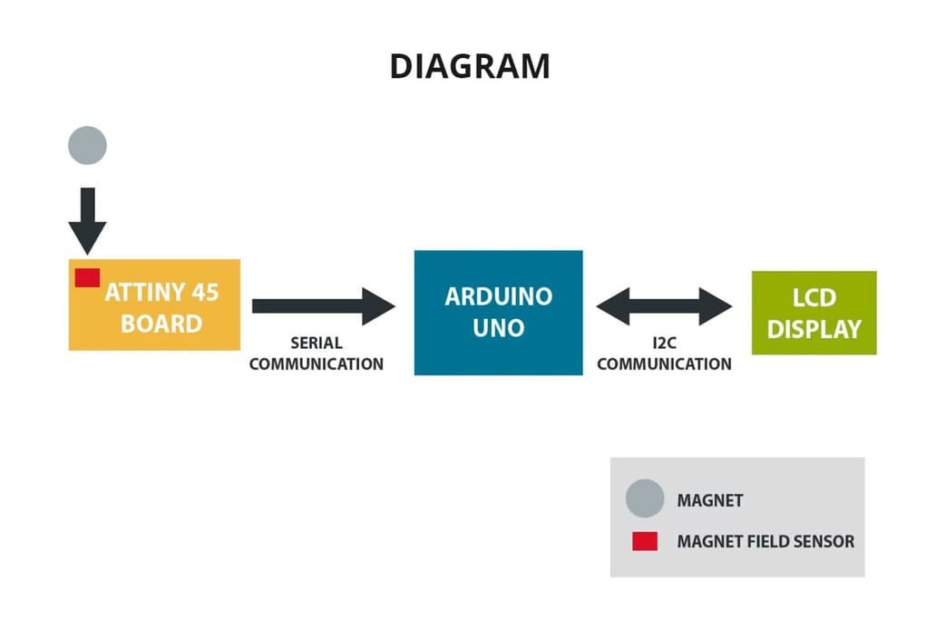
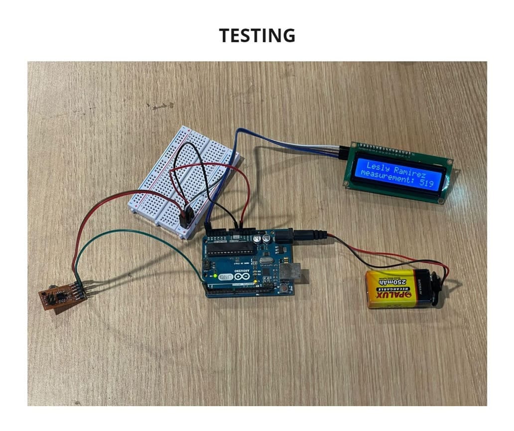
For the group assignment, we need to send a message between two projects. This task is documented on my classmate’s FabAcademy page, Lesly Ramirez.
In this example, a connection between an Attiny45 board, an Arduino UNO, and an LCD display is made. The Attiny 45 has a hall effect sensor, this signal is sent to the Arduino via Serial communication, and the Arduino is programmed to send the measurements to the LCD display using I2C.
Detailed info on this communication test can be found on the link provided here.