This week’s assignment is to use software to design in 2D and 3D and to render, animate or simulate our designs. So, we must try different software, evaluate it, and do a report on our progress using video.
I decided that I’ll be doing some more elaborated design sketches for my final project ideas this week because my first attempt for the Principles and practices assignment on week 01 was laking a little bit on the design part. I’ll be redoing them for this week using design software.
Developing the design
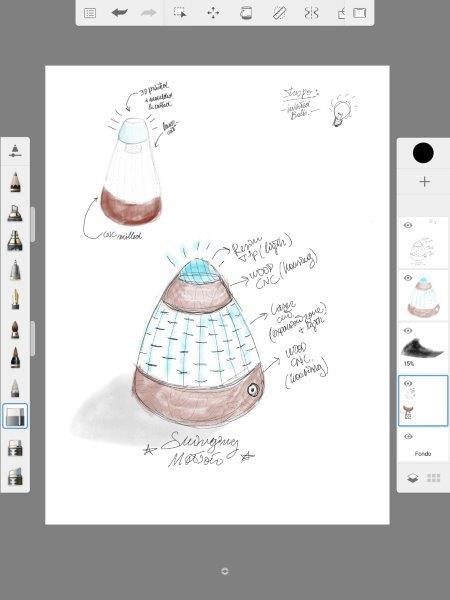
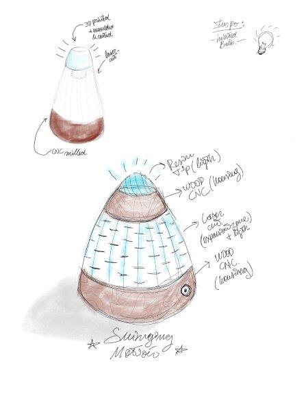
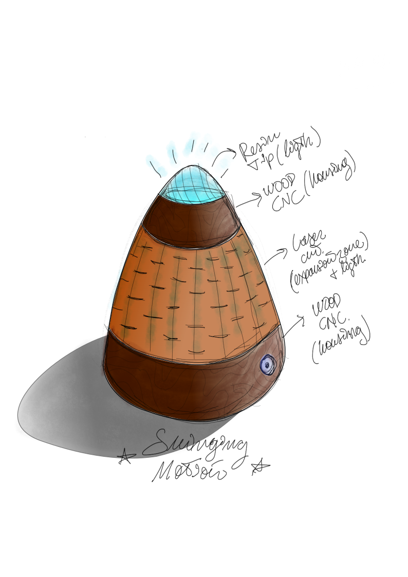
The original sketch design for the Office Mood Light Lamp (I’ll probably change the name soon) was a rounded square tower, that holds the electronics and actuator components at its base, the light feature in the middle, and the sensor on the top.

Because the whole concept of the lamp is to be conscious of the stress level in the office environment and to mitigate the stress, this tower shape seemed a little bit boring.
To find a less boring shape I took inspiration from a fidgeting toy I use while working that’s called a Mighty bean , this is a pill-shaped (rounded base and top) plastics toy that holds a ball bearing inside making it move like a roly-poly doll. Fidgeting helps reduce stress levels and improve concentration, so it seems natural that an anti-stress lamp should move.
Raster
I also wanted my final project to reflect the skills I would learn trough Fab Academy (also, it is mandatory) and these fabrication techniques to be visible in the final product. So I began doing some sketches:
I started working on my tablet because of the stylus using Autodesk Sketchbook, a raster drawing software, this has a free version available in the app store.
Here is a screenshot of the working environment, it has a simple yet classic interface with various brush shapes (left), multiple layers options (right) and transforms options (top).
Vector
I wanted to try the Inkscape software since this is open source and free. I already have fair use of Illustrator. I began trying to replicate my raster drawing in vectors.
I imported the image simply by dragging it to the workspace (could not find the import option!), place it in a layer named raster draw, create a new tracing layer, and started working with the draw bezier tool, to do it easier I turned the opacity of the drawing to 50%.
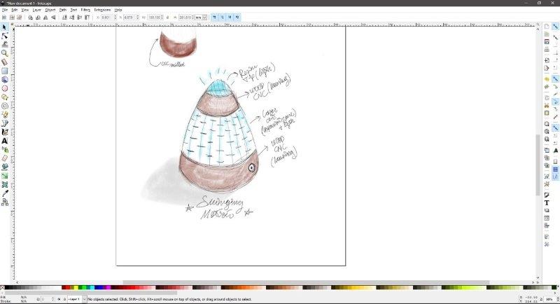
Next, I corrected the points on the bezier with edit paths by nodes tools, I filled the spaces between the paths with fill bounded areas and added some lighting effects with the gradients tool.
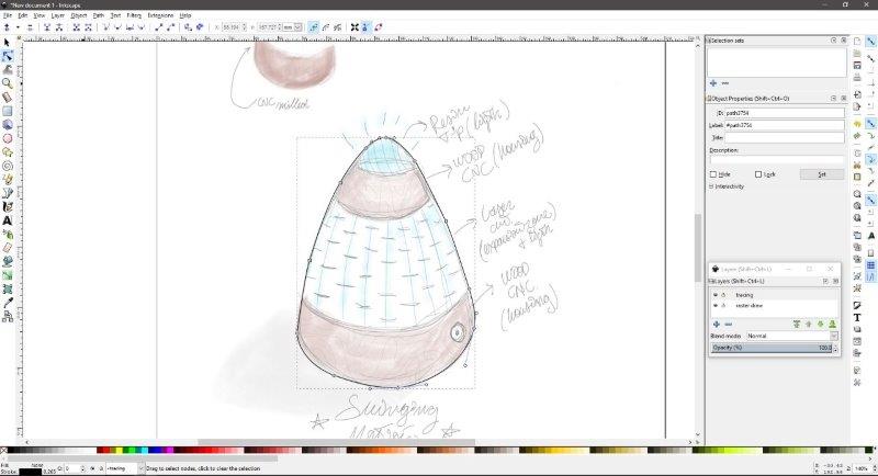
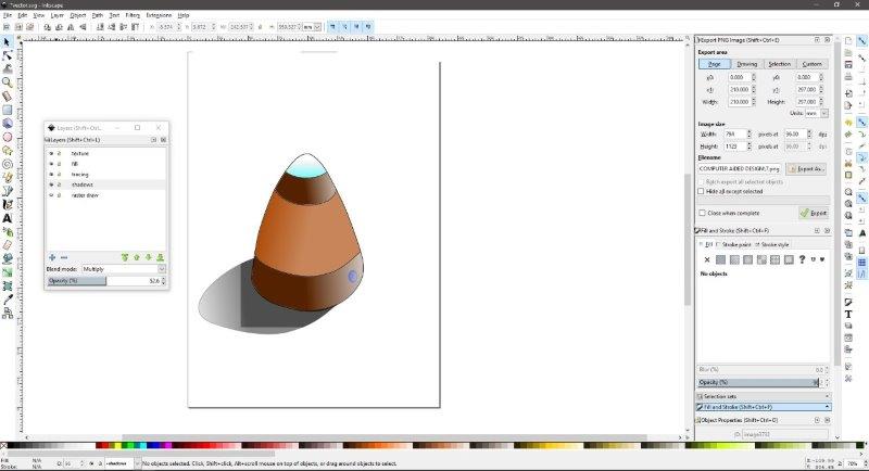
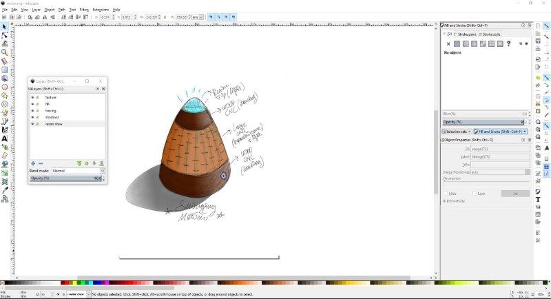
I changed the opacity and blending modes to combine the raster and vector drawings., and this is the result:
Download the vector (.svg) file here
2D
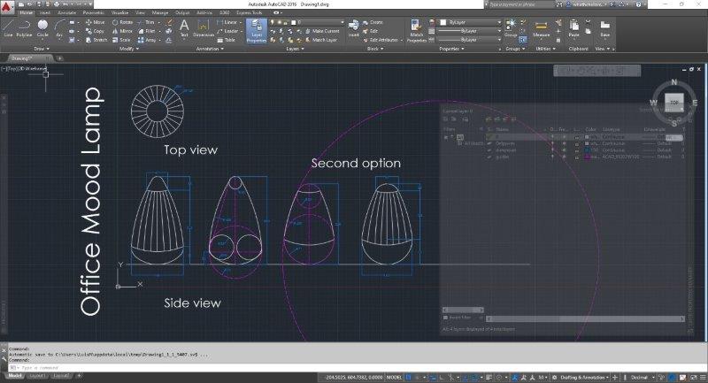
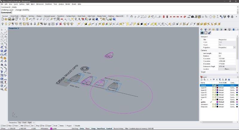
I started with Autocad (sorry Neil!) to make a 2D drawing to experiment/determine the size of the lamp. I choose the ACAD template and change the units to mm. I created a Guides layer (dashed line), and a Dimension layer (blue) and started some basic drawings with a symmetry line, and then drawing a circle to base and top, merged this two with the three-point arc tool, and used the tan,tan,radius to smooth the transition curves.
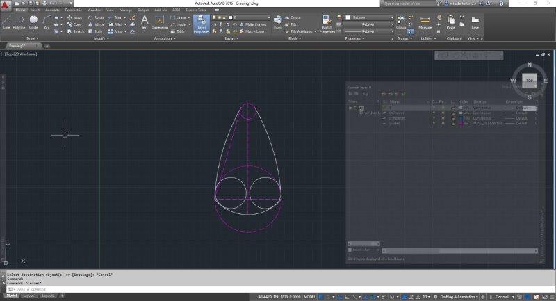
I did two sketches, one of 250mm height, wider at the base and pointier at the top, and another design with 230mm height, with a more rounded profile.
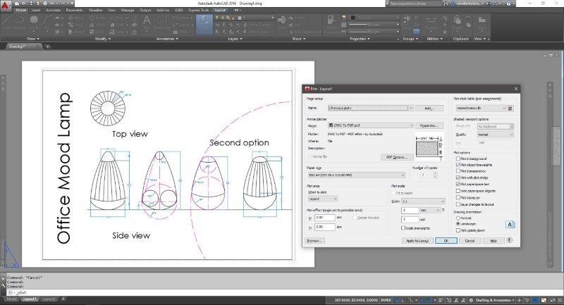
I exported the file as a .dxf (sorry again!) and as a .pdf
Download the 2D .dxf file here
Download the Autocad (.dwg) file here
3D with Rhino!
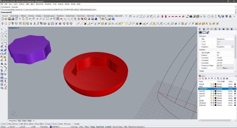
For 3D modeling, I started with Rhino using the dimensions previously drawn on Autocad, I imported the file from Autocad, erased some of the geometry and text objects and aligned the base of the design with the 0,0 coordinate (personal preference).
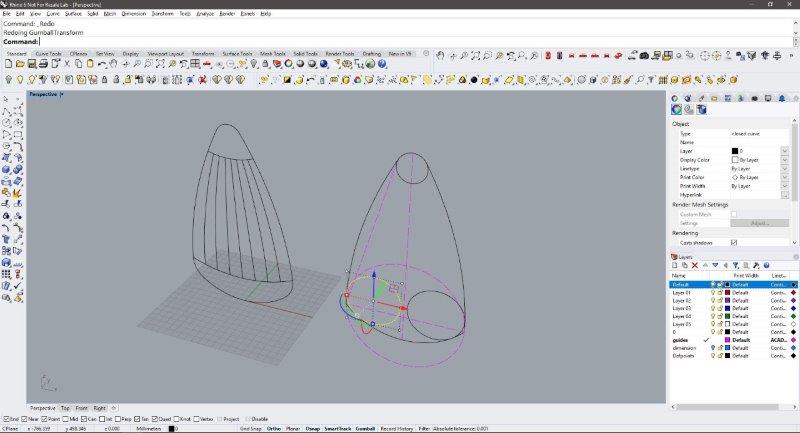
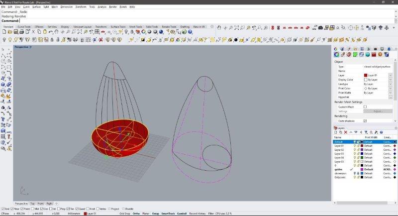
I decided I’ll start modeling the base, so I draw a central axis, an arc and a circle in a new layer using the imported geometry as a template, trimmed the lines and then join them in a single entity. I used this line to create a solid base, using the revolve command and selecting the central line as the revolution axis.
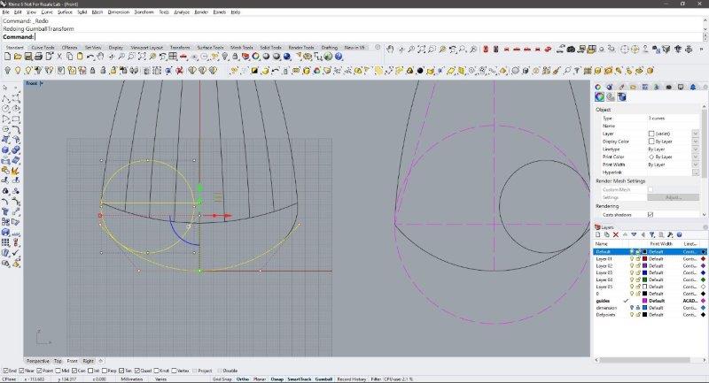

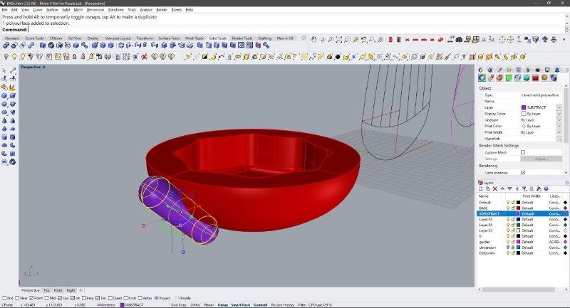
The Base should be heavy enough to balance the lamp and it should work as the housing for the electronics components, so a hole is needed, I used the command rectangle to create an 85mm square on top of the base, then using the command fillet corners selected the square and created the 10mm round edges. Note that Rhino has also a rounded rectangle option to do this in a single command.
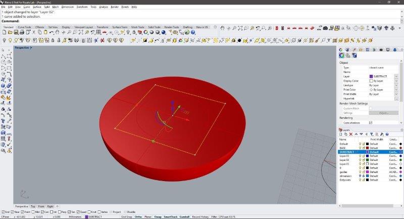
Having a circular base with a square hole would not look too good (also unbalanced!), so I’ve decided to create a more complex hole, I rotate and copy the square 45° using the gumball, and then draw an arc of 75mm radius between the curved corners using tan,tan,radius command and the copying it 8 times using the rotate and copy.

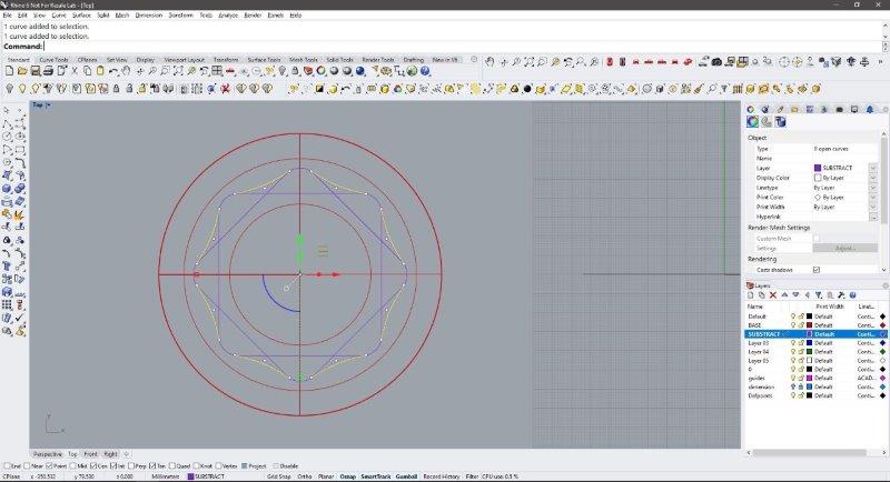
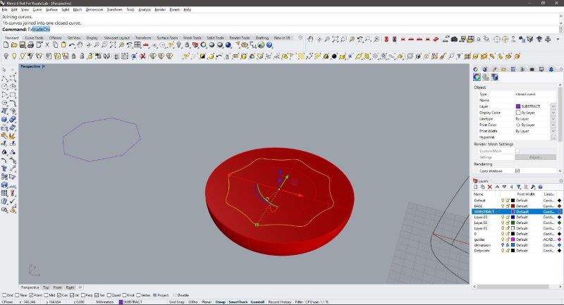
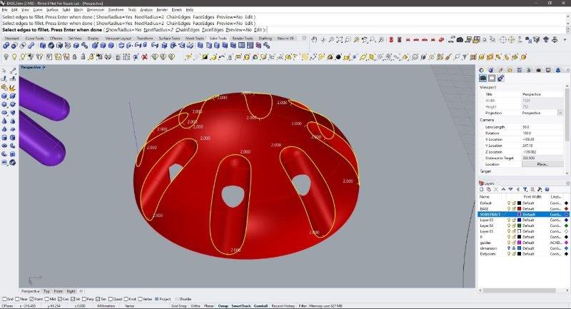
I trimmed and join this geometry to get a unique curve to make the hole on the base. I used the command ExtrudeCrv to do a negative extrude of 30mm (inside the volume of the base), and do a BooleanDifference operation to subtract the previously extruded volume. Next, I used Fillet edges to round the inside edge because why not (also for the CNC).
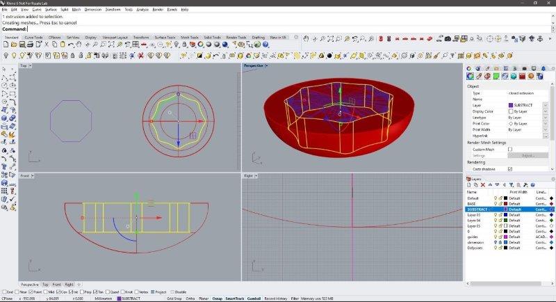
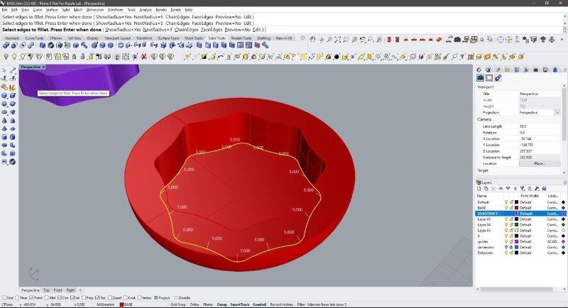
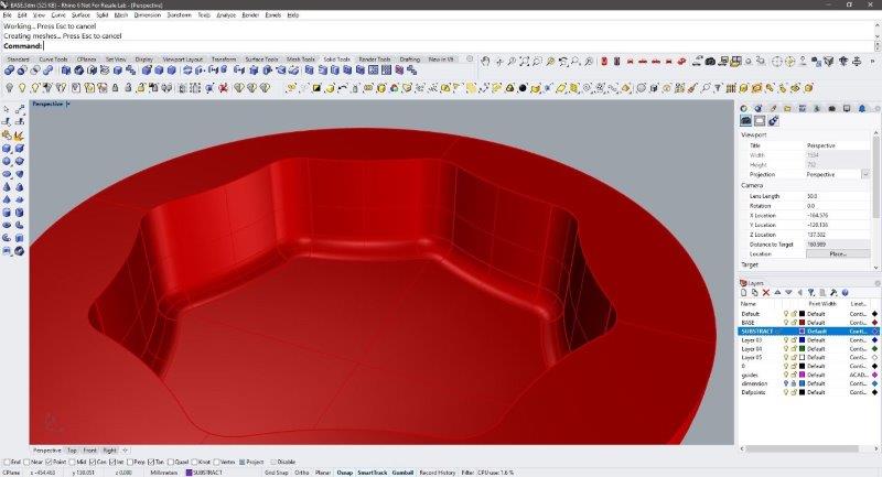
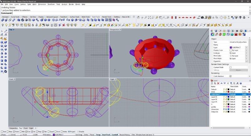
On the front view, I noticed that because I hollowed out the base, now the sides might be too heavy, so as a measure to decrease this weight I designed some vent holes, that should also make the design more dynamic. I draw a line with the same height and from the edge of the base, and later use this rail, to create a 10mm pipe round caps with the solid tool, rotated it 45° degrees and pushed it a little bit inside of the base.
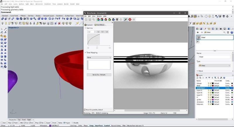
Next, I used the ArrayPolar command to copy this object 8 times around the center of the base, and repeat the BooleanDifference command to create the vents, so now these new holes align with the curves inside the base. And…one more 2mm FilletEdge on the newly created geometry for aesthetics. I assigned a basic metal material to the solid and did a quick render inside Rhino.
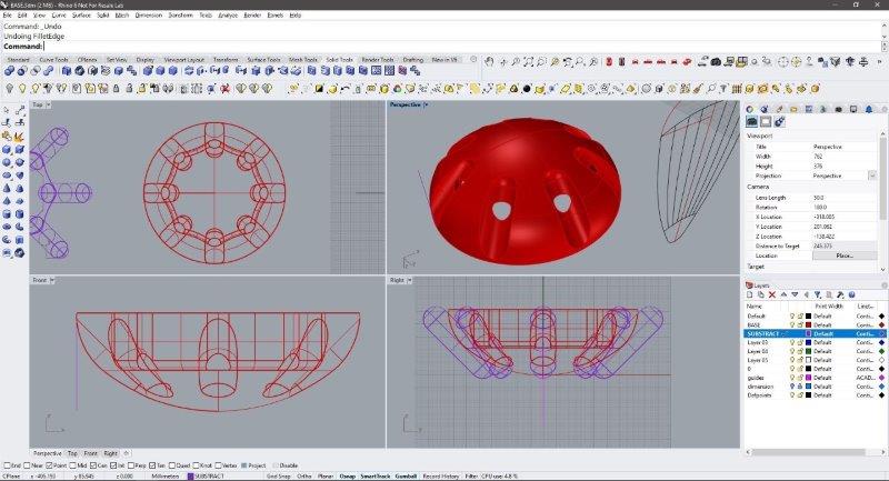
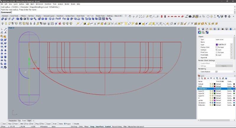
The native render is not very good, so I will be using another render engine. I Finished the shape of the lamp with the same technic, doing the contour line first, and then revolve around axis to model the middle part and the tip of the lamp. I exported the solid as a .obj object.
Some notes for future fabrication: Because of the shape of the holes the walls might be too fragile for CNC (could cause some dents), the clearance of the holes to the top of the base might be also too small. It is necessary to add features like holes for screws, room for the on-off switch, the pulse reader and the power cable.
Download the 3D .obj file here
3D with Fusion 360 (and Slicer)
I decided to try 3D modeling with Fusion 360 , although I am not very comfortable with the software yet, I feel like its a very powerful tool.
I started trying to replicate the 2D drawing in Fusion using the same measurements and did this with the create sketch button and drawing in the front view. First, I draw the symmetry line that marks the height of the lamp (250mm), next, the perpendicular line and the bottom circle of 75mm radius with the base arc, and then the tip circle of 35mm diameter. That’s where things got complicated. I needed to draw a tan,tan,radius circle but somehow the tangent snaps were not activating, I noticed that some of the sketch lines were in black while others remained blue, and maybe this was causing the issue, also, the snaps only seemed to work on lines but not on curves.
After many tutorials, reading, and try trimming, constraint/unconstraint, explode, new sketch, etc. still could not figure out what was wrong, and due to a recent update of Fusion 360, much of the troubleshooting advice was outdated. I could not continue because this tangent curve is crucial to the design and remembered why I DO NOT use Fusion 360 in the first place so I’ll be doing some online training.
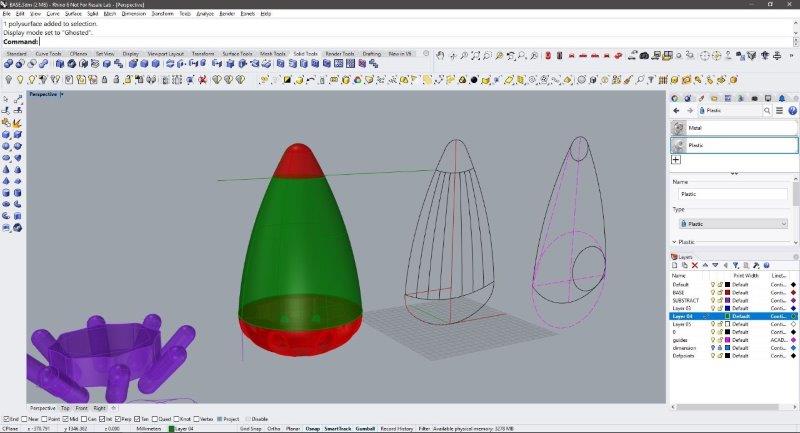
I decided I will be trying the create form tool that offers a sculpture-like feeling to modeling, and use this to try different forms that might work with the lamp design starting with 3 basic shapes: a sphere, a quadball, and a box.
These three basic shapes were modified using the edit form button, selecting the faces, dragging and scaling for the tip, and a final twist applied in the modified quadball to slim the profile, with these as result:
Using the Fusion 360 fabrication capabilities I’ll be testing these shapes in the real world. Using the slicer plug-in (under the Tools/Make menu) we can generate cutting templates to test the designs.
I tried the sphere shape first, to set up the material I used a custom template, of 900mm x 600mm sheet of 2mm cardboard and selecting a construction method of radial slices, and later editing the number of slices.
I also used the modify form option to hollow the interior of the shape, after this option some parts of the internal rings are in red. this means that have issues, but after a quick review, this doesn’t seem to be a real fabrication problem. So I exported the file as a .dxf with the get plans button. In this output file, the pieces need better positioning to achieve efficient use of the material, unfortunately, this got to be made by hand.
Using the template I repeated the process for the next two shapes (quadball and box) with more or less the same results.
Here’s a guide on how to sculpt in Fusion 360
Render with TwinMotion!
Twin motion is a simple, yet very powerful render engine, it’s based on Unreal Engine so it works like a real-time render oriented for architecture visualization. It is free (for now, and if you are an architect you have to try it) it has drag and drop materials and objects. I started importing the .obj file modeled in Rhino.
The first issue is that the import got the Z axis wrong, I rotated the object using the gumball like control. Next, I assigned the materials (selected from the left panel) simply by dragging it to the part I wanted to paint. I used wood and glossy plastic materials.
There’s ready to use glowing materials, and we can edit a blinking feature that is very convenient for my Office Mood lamp design. The scene is looking empty so I placed a desk form the furniture library of the left side panel, having the desk in the scene, we realize that the import also got the units wrong, so using the gumball (and guessing) I scaled it to 0.1 and moving around the gumball I managed to place the lamp on the desk.
Using the create image option I customized two scenes: a clay render, and a close-up shot of the lamp. This allows to independently choose the lighting and material settings, next I hit the export button and in about 1 second both render images are ready. To generate a video file I followed the same steps, create a scene, moving the camera, setting the video time to 5 seconds and export it using the same button, this shows the animation of the blinking pulsating light of the lamp.