Group Assignment:
- Test the design rules for your printer(s)
- Document your work and explain what are the limits of your printer.
We already had some printing tests in the FabLab, these were separated objects for checking calibration, testing wall thickness, overhangs, retraction, angles, etc. So we decided to print a multiple tests object.
Printing test files:
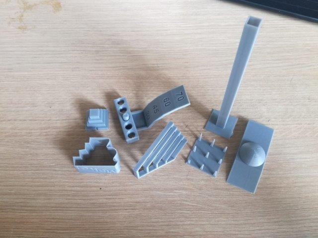
We selected and download a 3D model that has multiple tests, its called Ultimate Torture test. Find it here on Thingiverse.
We also printed a Lattice cube that test overhangs and retraction, and also a tolerance gap test that went wrong.
3D Printers
the 3D printing machines we'll be using for the test are:
Flashforge Guider II for the PLA print test, with a build volume of 250 x 280 x 300 mm
Zortrax M200 for the ABS print test, with a build volume of 200 x 200 x 180
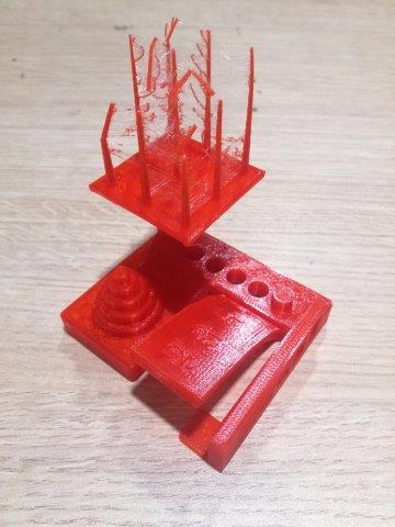
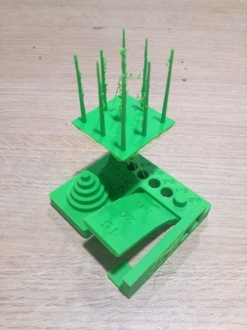
Test Results - Printed in PLA (red) and ABS (green)
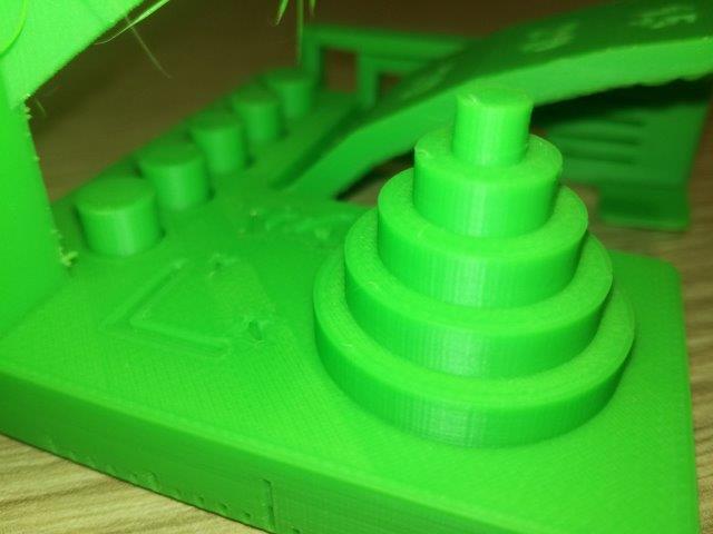
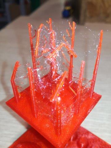
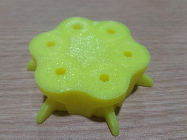
General view: both of the models came up quite well, the PLA (red) showed only flaws in the upper side of the spikes. the ABS (green) had flaws in every other part of the test, but overall the printing quality of ABS has smoother layering than PLA.
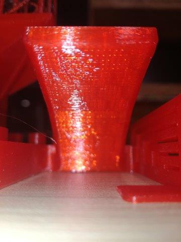
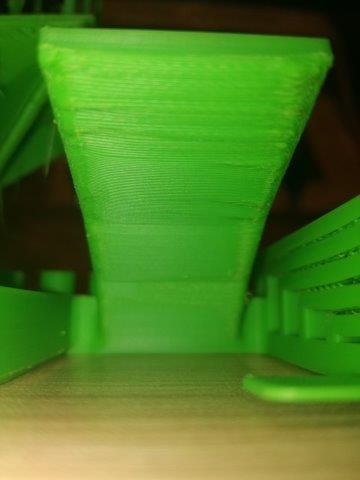
Overhang test: The overhang test for the PLA model went clean, only the larger bridge shows some of the bottom layers hanging slightly. For ABS this was not the best result, 4 of the 5 bridges shown flaws, being more evident on the larger gap as almost half of the layers shown overhang defects. This could be caused because ABS is a very sensitive temperature material.
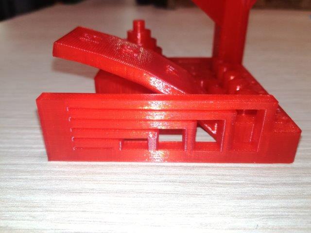
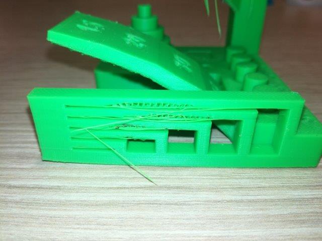
This is the same for the bridge in the upper part of the model, we can see the filament hanging on the bottom for ABS, but the superior layer came completely flat and smooth.
Layer smoothness test: Both models did great on this test, the layer quality is very clean, and the details like labels look defined. In this test ABS has smoother layering, it almost doesn't feel at the touch.
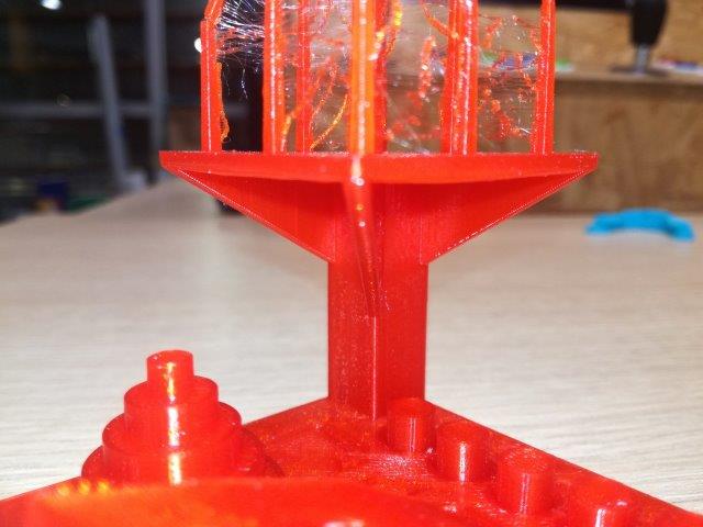
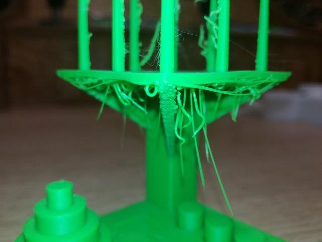
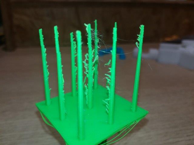
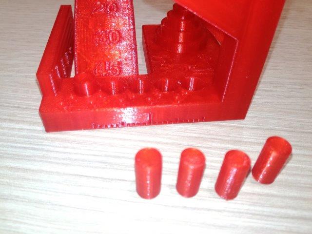
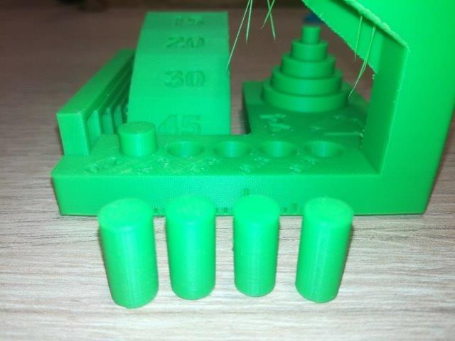
Retraction test: In this test, ABS did better than PLA, the spikes made in ABS are sturdy and have a little filament residue. PLA has a lot more retraction residue and the spikes are fragile. it is important to note that the spikes were broken after the printing.
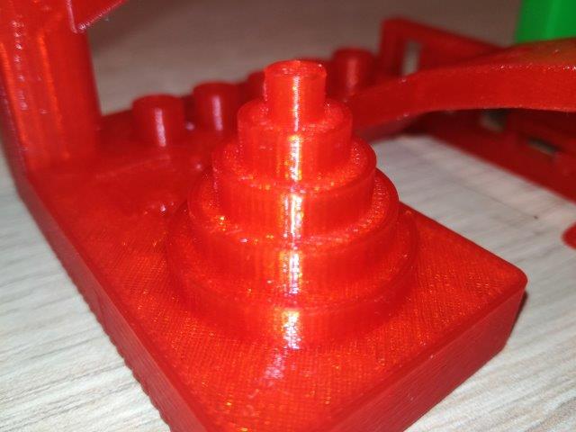
Overhang and angle test: Both of the printers did great in this test. it consisted of angle increments from 45°, 30° 20° and 15° (the last hanging part). These are views from under the hangs to notice the bottom layers. For PLA there is almost no difference from 45° to 15°. In ABS the last section of 15°, the bottom layers a little bit wobbly and there are minor flaws on the seams.
Gap test: Both of the printers did also very well in this test. the five cylinders are printed with a gap of 0.1 to 0.5mm, for both PLA and ABS the smallest gap of 0.1 caused the cylinder to be stuck (fused) with the model. While 0.2 to 0.5 fit easily on the gaps.
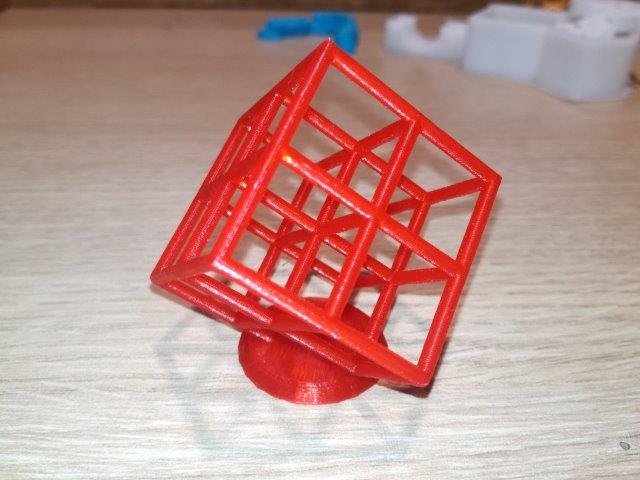
Lattice cube test: This model was printed with the same setting as the PLA model and in the same printer. It came up almost flawless, the overhangs of the cube are at a 45° angle, also the residue filament between the lattice is almost nonexistent. This seems strange because in the retraction test for the first model the filament is very evident. This might be caused by the speed in printing since the spikes of the first test were printing faster, and didn't have enough time to cool.
Gap test: This gap test was printed in the Flashforge Creator Pro, it did not work as any of the parts were moving. This might be caused by a defect in the model itself. The gaps range from 0.2 to 0.7, in the bottom part there seems to be a gap, but on the upper side, the parts are fused.

Individual assignment:
- Design and 3D print an object (small, few cm3, limited by printer time) that could not be easily made subtractively
- 3D scan an object, try to prepare it for printing (and optionally print it)
3D Printing a small object
The goal for this assignment is to design and 3D print create a small object that could not be easily made subtractive. After the group assignment to test and characterize the design rules for the 3D printer, I decided to take this test a step further with a hollow sphere design with a few supports and made a simple grasshopper definition.
The design
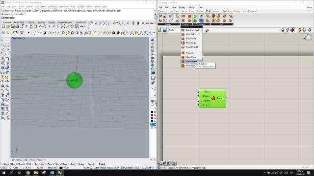
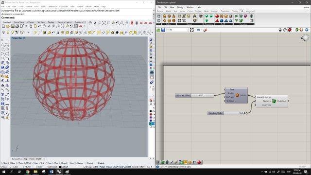
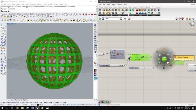
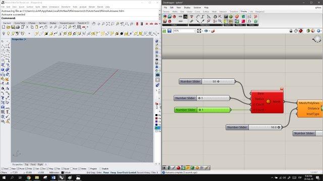
The software is Rhino 6.0 and Grasshopper. First I started creating a mesh sphere from the Mesh/primitives menu, this is very important, as the plugin I'll be using for the definition works with mesh objects and not with nurbs.
The plugin Weaverbird (in words of the author) is a topological modeler that contains many of the known subdivision and transformation operators, readily usable by designers it is available here.
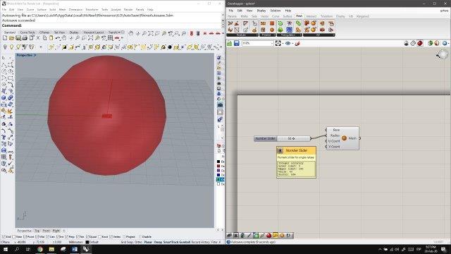
After we created the sphere we need to give it a radius parameter, we create number slider simply by double click the canvas and enter the number 50. This will generate a sphere of 100mm diameter that could later be scaled to 50%.
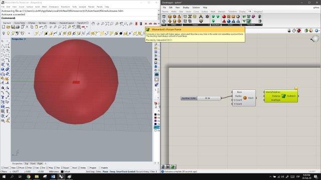
From the Weaverbird tab we select the Weaverbird picture frame node, this will create a frame from the wires of the mesh. next, We link the sphere geometry to the mesh polylines input.
We proceed to hide the sphere to better see the frames, we create a number slicer to control the distance of the frames, notice that this geometry is flat.
Next, we select the node Weaverbird mesh thicken, this will give volume to the frames, we add a number slider to control the thickness.
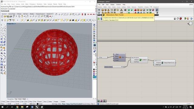
As the thickness is in mm, we select a value of 4, considering that the limit for wall thickness in our 3D printer is about 2mm.
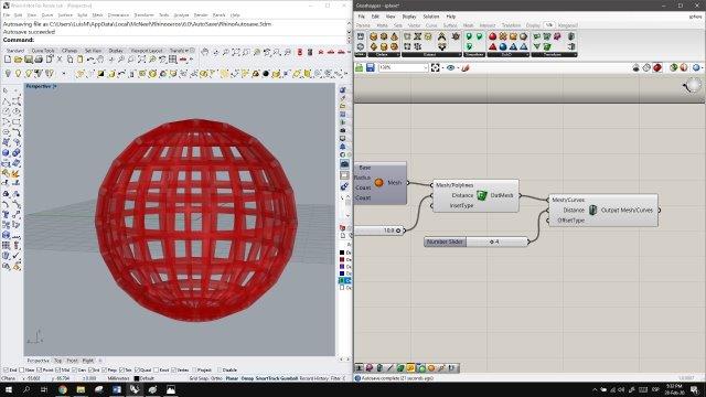
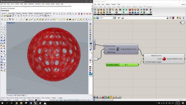
Next, we add the Weaverbird carmull-clark subdivision node. this will give the frames a rounded profile without losing the thickness.
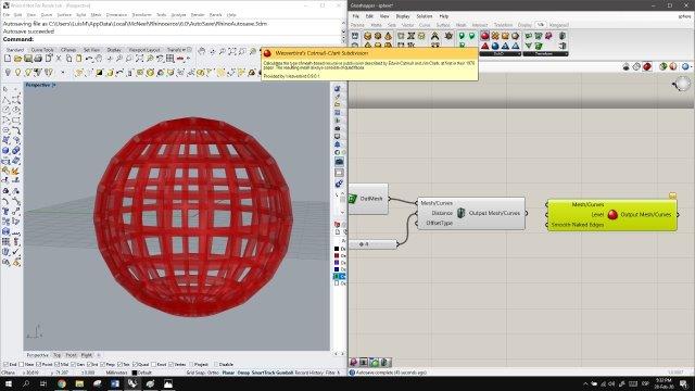
To better see how this node works we select the previous nodes and with the middle click select hide.
Next, we add a level parameter of 3 for the smoothness, notice that the geometry changes to almost circular holes.
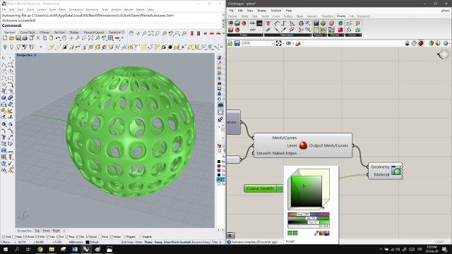
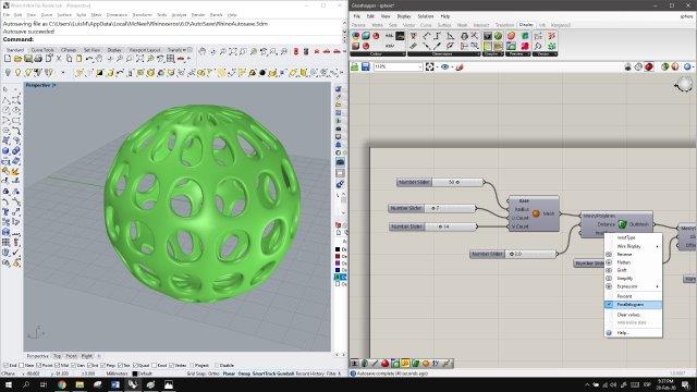
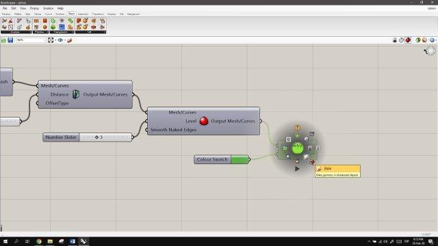
To better show the new geometry we add a custom preview node. from the display tab.
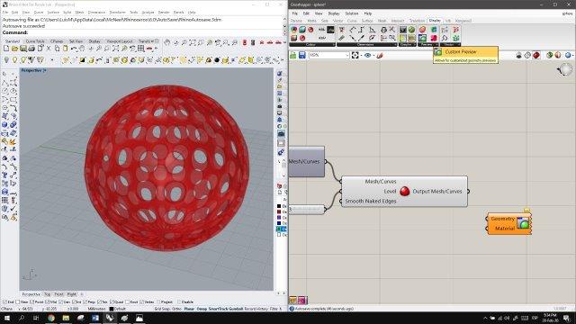
We link a colour swatch node to the material input of the node, to let us pick up the color.
At this stage the mesh sphere is regular, it has the same subdivision in the vertical and horizontal plane, we can change this adding number sliders to the U count and V count of the original geometry. Notice that once we link the number sliders are un 1, and the sphere disappears.
Then we change the parameters to 7 and 14 to double the mesh divisions in one direction. next, we change the option of distance in the frame node from percent to parallelogram because we noticed that it works better.
We'll be scaling our model to 50% to create a small object.
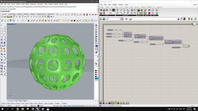
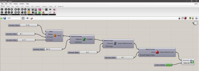
Done! this is our complete definition in grasshopper.
finally, we select the last node and hit bake, to transform the Grasshopper definition to Rhino geometry. Next, we select the sphere from the Rhino window and export it as a .stl file.
Printing settings
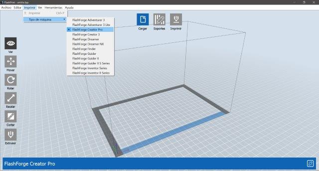
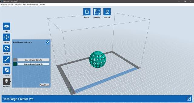
I used the Flashprint slicer as I would be working with a FlashForge Creator Pro 3D printer. First, I set up the printer and then load the file.
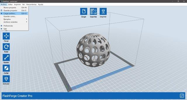
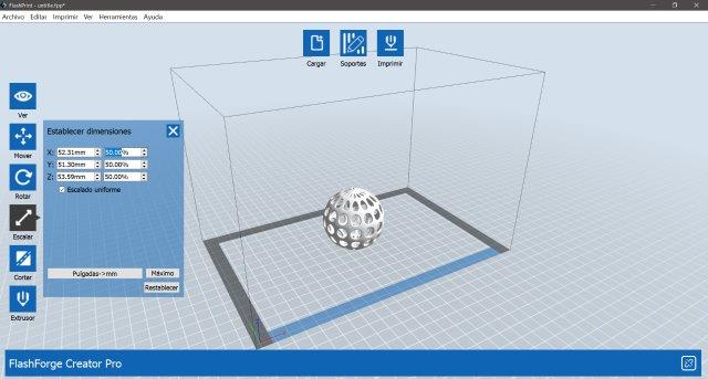
As the original file is a sphere of approx. 100mm diameter, I scaled it to 50% to get a 50mm diameter ball.
Next, I selected the extruder that has the filament loaded, (left one) notice how the volume change color to match the extruder. The next step is to create a support structure, The Support button is located in the middle-upper part of the slicer window.
This opens a window to configure the support structure, there are two options to choose the type of support: dendritic and lineal, I choose dendritic as its faster and waste less material.
These options also include the angle limit (45°) but this is for the autogenerate support option, the post diameter, base of the post diameter and height of the base.
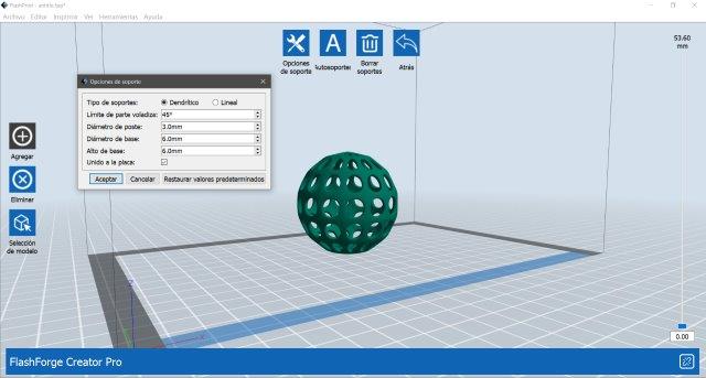
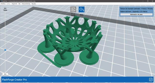
I choose to draw the supports instead of automatically generating them, also this allows to keep the number of supports to a minimum amount, and keep them outside of the sphere.
For drawing the supports we pick a slicing plane on the sphere (marked with a white line) and then click and drag the support to the base of the printer platform. I choose to place the supports in the lower part of the sphere and draw this like branches (from one base, there are 3 support points).
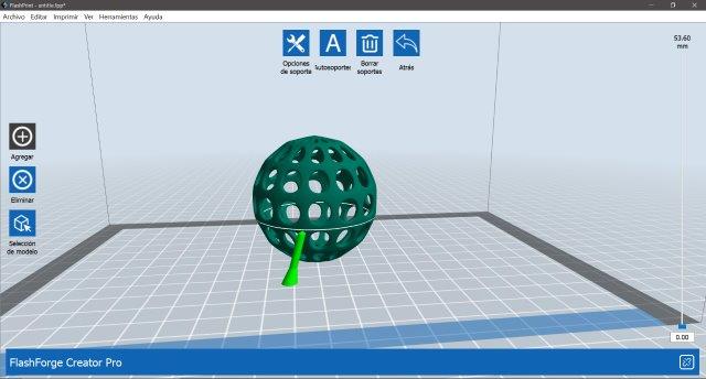
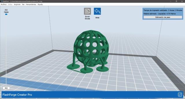
The final volume with the support structure
Next, we set the printer settings, as I would be working with PLA I kept most of the settings as default (as I tried before in the group assignment and it proved to work fine). I only added a base, as the sphere would be supported only by this point until the supports join. This proved to be a risky move, as I would notice once I send it to print.

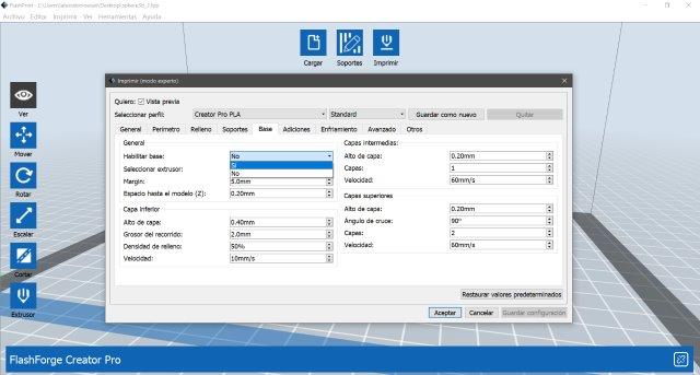
The print settings go as follows:
Layer
- Layer height mode: Fixed layer height
- Layer height: 0.18mm
- First layer height: 0.27mm
Temperature
- Extruder: 200° C
- Platform: 50° C
Speed
- base print speed: 60mm/s
- travel speed: 80mm/s
- min. speed: 5mm/s
- max.speed first layer: 20mm/s
- max.speed first layer travel: 70mm/s
Retraction
- lenght: 1.3mm
- speed: 30mm/s
The final step is to simulate the slicing, the estimated printing time is about 3 hours and around 4.7 meters of filament for 302 layers. I exported the G- code to an SD card.
The print!
This is the 3D printer that'll be using: Flashforge Creator Pro, with a build volume of 227 x 150 x 148mm.
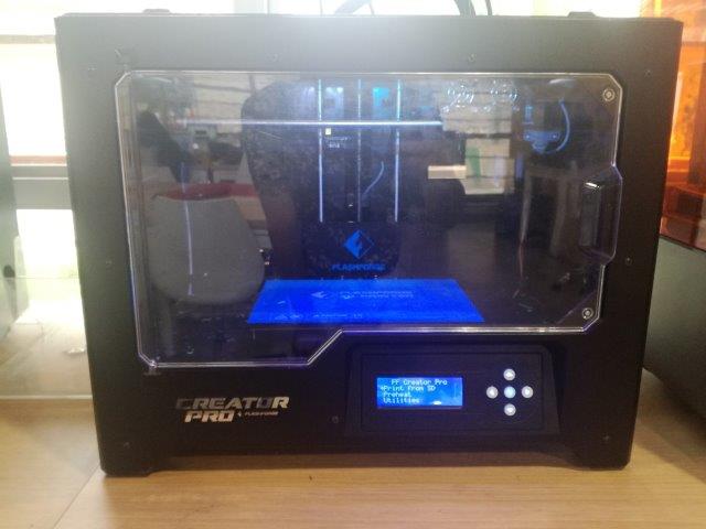
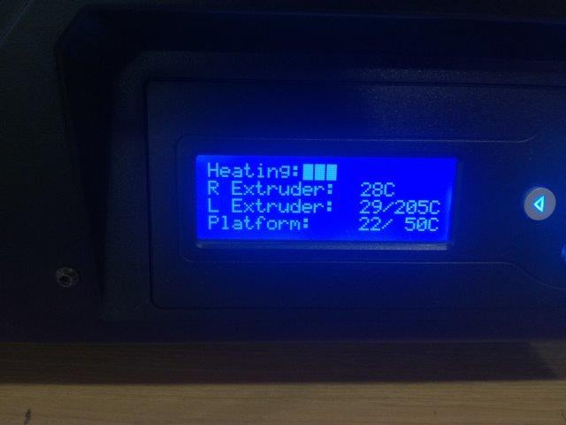
PLA doesn't need a heated bed, but it is advised to work with bed temperature of 50° to improve adherence. So heating…
The printing process went very smooth:
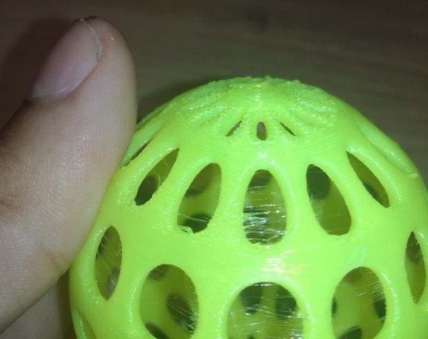
The only risky thing was the lack of support structure in the bottom layers, as the sphere had only one support point until almost half of the printing process. I do not recommend this as it could cause the structure to collapse.
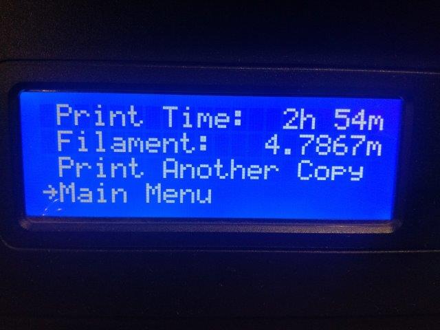
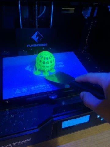
The printing time was 2hours and 54 minutes, very close to the software estimation, also the filament used is the same as the software indicated. To retrieve the print I used a paint scraper.

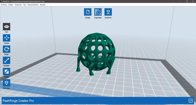
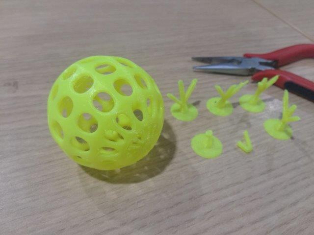
The support structure was easily removed by hand. only one of the support branches broke as it was a flaw in the print, and the support was touching the sphere in more than one point. This was removed with a set of small pliers.
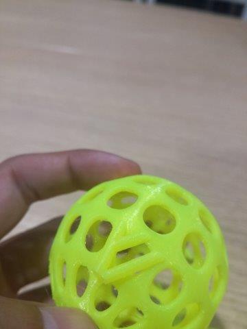
This is the final print. It has very small filament residue of PLA in the holes (maybe a little tweak in the retraction parameter would help) but the size of the sphere is also an important consideration.
This design is possible but not easily made subtractively because of the hollow part of the sphere, removing the material would be very hard to make with any tool, even for a 5 axis cnc machine. Also, the size of the sphere, the tickness of the walls an the changing hole pattern on the surface makes it a real challenge for a subtractive method. But it is easily and quickly made in a 3D printer.
3D Scanning
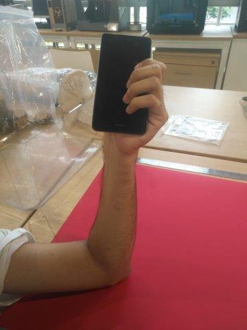
I would try a phone holder for this exercise, But my phone holder would be a 3D printed version of my hand holding my phone like this:
But first I would scan a small object to test the 3D scanner and the scanning software. The scanner is a 3D Sense. and the software I'll be working with is Skanect.
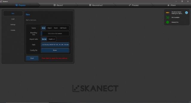
The workflow goes like this: Connect the 3D scanner to the computer, open the Skanect software. This has 5 steps to guide the scanning process:
Prepare: In this stage, we set what kind of object would be scanned, in this case, I selected Body and because it is only one arm I pick a bounding box of 0.6 m. once this is set we hit the Start button.
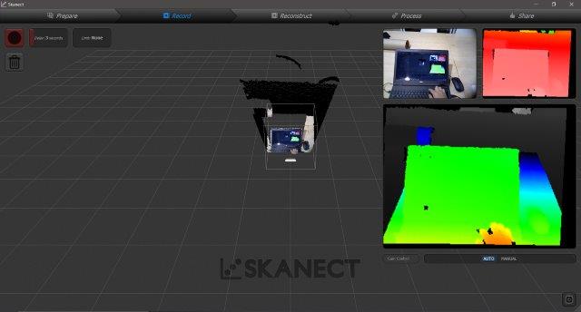
Record: This stage is for placing the object/body to scan and point it with the scanner, we need to have a working distance of approx. 35 cm to the object, In this case, the orientation of the scanner is horizontal.
The side views indicate the correct distance scanning distance in green to a blue hue. Once I got the object in place I press the record button on the upper left side of the window. notice that I have a 3 delay second to start the scan.
It is a good recommendation, to plan the scanning movements or how you would be moving around the object.
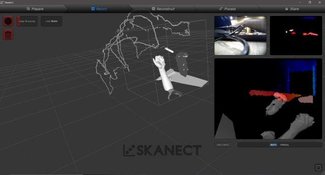
Trying to scan my arm, proved to be extremely difficult, so I requested a friend to pose as a hand model. unfortunately while doing the scan I was not able to take screenshots of the process, as any kind of sudden movement would cause the scan to fail.
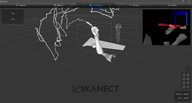
Once I stopped the recording, the software would generate a volumetric preview of the scan. In this image, we can see the path of the scanner around the arm, part of the face of the model, and a part of the table.
Reconstruct: Next we press the reconstruct tab, this would process the scanned geometry and save it to a file, in this stage we can resize and place the bounding box to fit what we want to keep, but we'll be cropping it in the next stage.
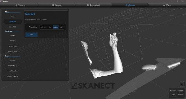
Process: In this stage, we select the watertight options, this allows the software to close any holes in the mesh. I also did a medium smoothing to the scan.
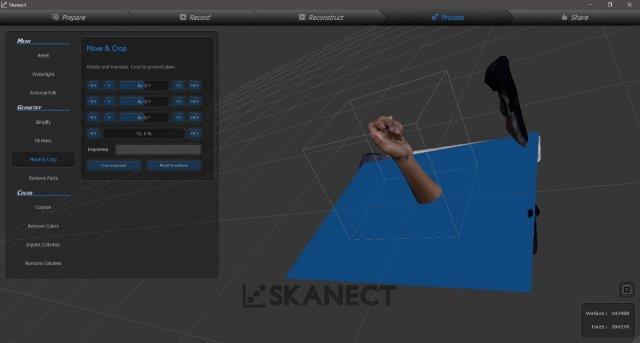
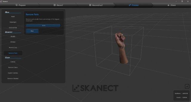
In this stage I proceed to crop the scan, selecting only the hand and part of the arm. Notice that this adds the texture to the model. There's also an option to remove parts from the model.
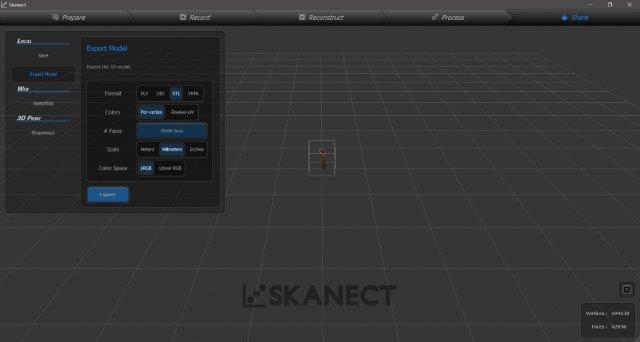
Share: This stage is for exporting the model, I select to export as .stl (not textures allowed) and to process the volume later in Meshmixer.
Postprocessing the scan
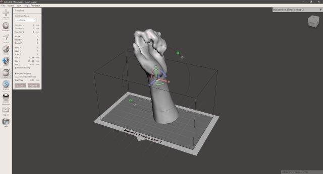
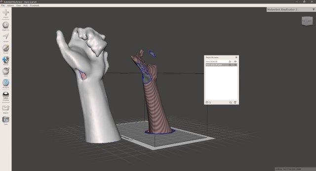
I used Meshmixer to clean up the .stl and fix some issues of the scanning. I imported the model and center it with the transform / align option.
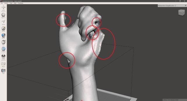
After close inspection, I notice some holes and errors, like other not so smooth geometry in the hand like a crease in the side and errors in the thumb.
To fix the holes I select (orange) the outside mesh and then copy it as a different object.
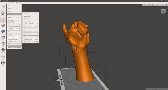
This allows me to separate the "hole" (in pink) from the model and to erase it, next I generate a solid geometry with the mesh to start filling the gaps. The Make solid option is under the Edit button.
After the mesh is solid (similar to watertight in the Skanect software) there are still some imperfections in the model, some of them caused by flaws in the scan process.
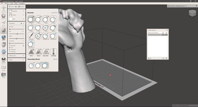
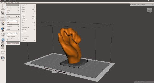
To clean these imperfections, I used different brushes, under the Sculpt option. The most useful brushes (for me) are: Robust smooth, Bubble smooth, Flatten, and Inflate. We need to vary the size and strength of these brushes to sculpt the model.
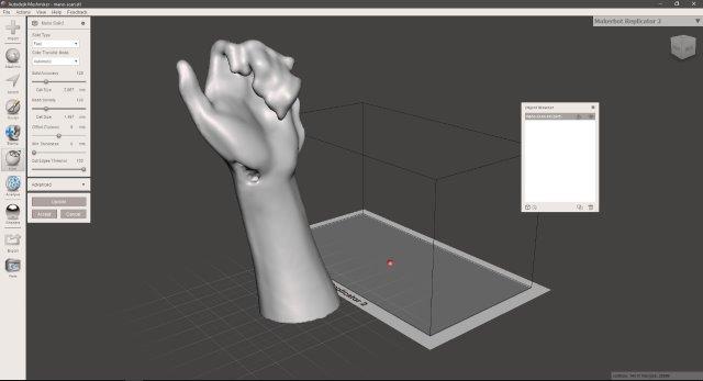
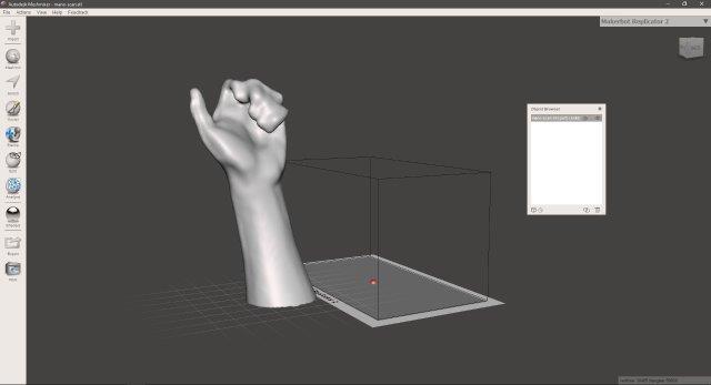
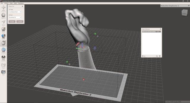
After smoothing out the imperfections we got a clean hand. But this model remains too big for the printer, so I decided to cut it to the wrist. For cutting, I used the Plane cut option on the Edit button.
We can select the height, axis, angle, and orientation for the plane cut with the gumball like controls. once the plane is set and hit Accept, this will automatically discard the cut part.
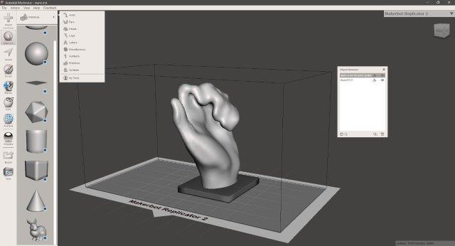
As the model needs stability to be printed, we pick a base from the Meshmix button, the base is a modified cube and attached to the base, by this step the hand and the base are separated solids.
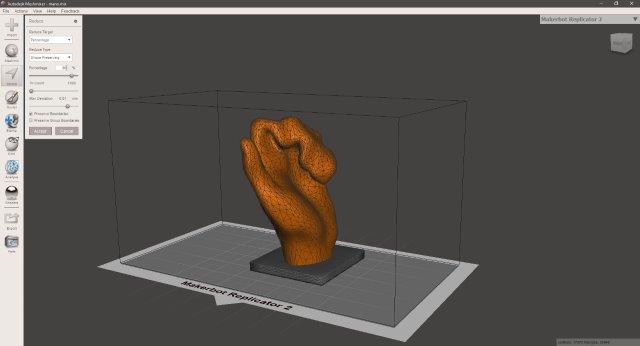
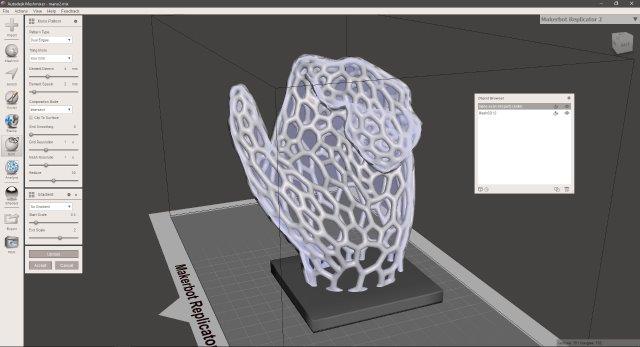
As the scan model does not look too good I decided to convert this solid geometry to a Voronoi pattern. For this, we first need to reduce the number of polygons, We select the hand and then Select / Edit / Reduce. To be able to see the polygons we press "W". I reduced the polygons to an 80% two times, trying to get the minimum amount of triangles but still a decent shape of a hand.
To generated the Voronoi structure, we used the Make Pattern option on the Edit button. I selected the Dual edges pattern type and play around with the settings. Be careful because drastically moving the settings would use a lot of processing memory.
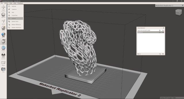
Next, we select both the solids and hit Combine, this will merge the solids into one. Then I exported the object as a .stl file.
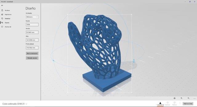
This is the finished object in the windows 3D viewer.
Some notes: The resulting scan didn't come up very accurate because I did not plan the scanning route in advance, this caused that I could not completely move around the scanned arm, so I was reaching those hidden points moving the scanner in awkward positions. At some point during the scanning, the scanner moved rapidly, this did not interrupt the scanning but created a double geometry issue as seen on the fingers.
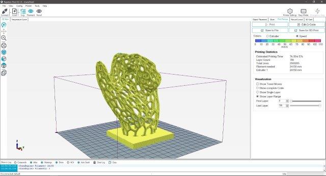
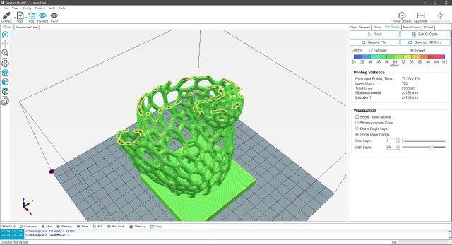
The print! (not really)
I used Repetier software to quickly slice the model. It'll take around 7 hours and a half to print, and use 24 meters of filament for 705 layers.
I think that it would be a good idea to print the phone holder in a flexible filament, as this would better secure the phone, but the model needs printing support and for flexible printing, water-soluble support is ideal. unfortunately, we do not have this kind of filament available at the time.
3D Models and Downloads
Download the grasshopper definition of the Hollow sphere here
To download the 3D files, click the download icon (top-right corner) in the viewer, this will redirect to Sketchfab and let you choose the file format to download (by default is .stl).
Other option is to click view on Sketchfab blue icon (bottom-left corner) and then select the download 3D model option from the website.