Characterize your laser cutter
The laser cutter we have in FabLab ESAN is a Trotec Speedy 400, equipped with a CO2 laser and a bed size of 1016mm x 610mm.

The standard workflow is exporting a .dxf file from any CAD software, open CorelDraw, import the file, selecting and painting appropriate color codes for cutting settings (if necessary), select print (the Trotec act as a printer), this opens the JobControl Software, the machine cutting interface.
Here you can set up various parameters. It normally works with RGB color codes, black for engraving, red for cutting, and many others like green, blue, yellow, magenta cyan, etc. that can be customized for power, speed, Hz / PPI, passes, air assist, offset-z, and advanced according to each color.


Focus
This is the first parameter to set, we calibrated the focus manually using a metal guide that hangs from the laser pointer moving the cutting bed up (with the material to cut already placed) until the material touches the base of the guide and falls. I noticed that the focus point is quite close to the material, about 10mm.
Power and Speed
Power and Speed settings are closely related and are expressed in percentages, settings go from 0.01% to 100%. The JobControl Software comes with preloaded settings for engraving a cutting different materials like paper, plastics, wood, solid wood, leather, fabric, etc. I used this as base settings for cutting and engraving tests.
Power seems to influence kerf in materials like cardboard and MDF. More testing required.
Frequency
Expressed in Hz goes from 1000Hz to 60 000Hz for cutting, and 500 to 1000 PPI for engraving
Cut, Kerf and Joint clearance
I made a rectangular test cutting template of 140mm by 75mm with ten 20mm squares holes and tested it on 2mm Cardboard, 3mm Acrylic, 3mm MDF, and 4mm Plywood. The results go as follows:
Download the cutting template here
Cardboard 2mm
The cutting template is 140mm by 75mm with ten 20mm squares. The test consists of varying the parameters for each square using the Trotec 400 default setting as reference.

The first square corresponds to the default settings for cutting 2mm cardboard (P. 85 / S. 1 / Hz 5000) For this test, the speed and Hz settings remain the same while the power decreased by 10% on each square, we start with 100% power to 20% for the last square.
I noticed that the default power cuts the cardboard, but also does a power setting of 60% and 50% with a clean cut and much less smoke. 40% power almost cut thru the material, but the pieces remain attached. 20% seems like a good setting for marking line text, faster than engraving and clear to read in cardboard.

For engraving, the default setting of the machine for this material is P. 60 / S. 60 / PPI 1000.
For the first engraving test, the speed and PPI settings remain the same while the power decreased by 10% in each square, which is from 100% to 10% power. From 100% to 50% power the engraving works well, the main difference is in the deep of the engraving, 70% and less it is hard to see in cardboard. the 40% produce an almost white-silky engraving that looks very good. 30% and less didn't produce any engraving.
There was an issue with the machine recognizing the yellow layer (corresponding to 80% power) and this engraving setting was not plotted, I later assigned other color to this setting.

For the second engraving test, the power 60% and 1000 PPI settings remain the same while the speed increased by 10% in each square, which is from 10% to 100%. Speed of 10% produced a deep engrave, leaving only the back paper layer of the cardboard (but looks charred).
Speed of 20% vaporized the upper paper layer of the cardboard leaving the wavy pattern exposed. This setting could be useful for bending applications using the cardboard material orientation.
A speed of 80% and 90% produced a white engraving similar to the addressed before.


Transparent Acrylic 3mm
The cutting test with acrylic was using the same template as the cardboard. The default setting of the machine for this material is P. 100 / S. 0.55 / Hz 5000.
For this test, the speed and Hz settings remain the same while the power decreased by 10% in each square, which is from 100% to 10% power. The default setting (100% power) was the only setting barely able to cut the material, but this was not a perfect cut, one side inside the square-cut has some dents. This cut could work better by decreasing speed to 0.50 or 0.45.
The square piece is 19.95mm and the square hole is 20.05mm, around 0.10mm difference of kerf.


The 10% power cut felt almost like an engraving because it barely marked the surface. On a side view of the material, we can see the penetration of the laser according to the power setting.

For engraving, the default setting of the machine for this material is P. 100 / S. 0.65 / PPI 1000.
For the first engraving test, the speed and Hz settings remain the same while the power decreased by 10% in each square, which is from 100% to 10% power. From 100% to 60% power the engraving looks almost the same, the main difference is in the deep of the engraving, and from 50% to 10% there is no engraving. Therefore I recommend using less power (60%) for simple engraving and full power less speed to get a deep engraving.

For the second engraving test, the power and PPI remained constant by default setting, while the speed varies from 10% to 100% in each square. In the first square, with a speed of 10%, we got an important engraving of 1.15mm deep.

Some notes: I forgot to peel the protective plastic film on acrylic and this resulted in a messy engraving as seen on the letters to the first test. I also forgot to round the corners this could be potentially dangerous cutting hard materials like acrylic
Plywood 4mm
The cutting test with plywood was using the same template as the cardboard. The default setting of the machine for this material is P. 100 / S. 0.8 / Hz 2000.
This setting did not cut the plywood and as the power decreased with each square, none of these were cut. I noticed that the default setting produced flamed and a lot of smoke. Since power is at max, I figured it is better to do at least 2 passed with less power. Upon consulting this idea the instructor told me that is it better to work with 5000 Hz (max) for cutting.

I decided I would do a second test of one square with P. 80 / S. 0.8 / Hz 5000. but this time using two passes since I noticed that 80% power did not produce a flame. This test barely cut the 4mm plywood, it did not produce flame on the first pass but it did on the second one, and it's not a good option. Seems like the way to go is one pass with full power (100%) less speed (around 0.60) and 5000 Hz.

I tried this cutting parameter with the engraving test, still did not cut the plywood. Less speed (.50) and more Hz (6000) might work. Spoiler: It did NOT. For engraving with power variation, I used 100% speed and 500 PPI, power from 100% to 70% did produce engrave, 60% and under did not engrave. For deeper engraving less speed and higher PPI.


Some notes: I was using a slightly bent plywood sheet and this was messing the cutting power since some sides of the template were cutting better than others (I suppose it was a focus issue), so I'll be trying with a more stable material next time.
MDF 3mm
The cutting test with MDF was using the same template as the cardboard. The default setting of the machine for this material is P. 100 / S. 0.6 / Hz 5000.

For the 100% power, the square piece is 19.92mm and the square hole is 20.13mm, around 0.21mm difference of kerf. For the 90% power, the square piece is 19.90mm and the square hole is 20.09mm, around 0.19mm difference of kerf.


For the joint clearance test, I used a template that resembles a comb. Each of the spaces between the pins has a difference of 0.2mm taking the middle space corresponding to the thickness of the material: for MDF and acrylic its 3mm, the spaces to the right go from 3.02mm to 3.12mm, and to the left, from 2.98mm to 2.88mm; I also used 1.5mm cardboard.
Notes: Materials do not have the exact thickness. For the 3mm acrylic used the real thickness is 3.24mm and the 3mm MDF is 3.12mm. So this is crucial when working press-fit pieces.
It is hard to measure kerf in such tiny spaces. working with the digital caliper I got several measurements of the same holes (error factor, especially with soft materials like cardboard and MDF) so kerf is approximated.
Parametric Press-fit Construction Kit
Doing the cardboard cutting test I noticed that a setting could cut only through half of the material, leaving the paper backside untouched, this worked as a hinge.
I begin exploring (but not parametric yet) using 1.5mm cardboard to make pieces that can be cut flat, and then bent to form different pieces, the idea is not having just a fixed piece, but one with different possibilities depending on the bent direction. This complete bent made the material double the thickness (3mm), so the notches were drawn according to this size.


For the first test, I've used 3 different pieces, each one can bend to make two different forms.

One piece, two bending options:


The four pieces cut can join to form many combinations: (notice the architecture resemblance huh?)


This proof of concept design was made un Autocad as a 3 piece set, that can fit together to reduce the material waste.

Now I’ll try to make them parametric with Rhino and Grasshopper, using the concept pieces as templates. The 3 pieces fit in rectangular shapes.

The first step is to draw the notch in Rhino, my pieces have only one type of notch (3x20mm) adding some chamfers to the corners for a better fit between pieces. As this will be parametric we could change the geometry of the notch later.

As the pieces are rectangular-based I created a definition that holds a parametric square with number slider, construct domain, and rectangle nodes, the resulting square (green) is 80mm by 80mm according to the sliders.

Next, I set the reference points for the notches, this is made by “exploding” the rectangle into independent lines, and setting points in reference to the length of the line with a number slider, in this case by 0.5 (middle of the line).

Now, to insert the notch in these points I created a separate definition (will later merge with the previous one) with curve node (to pick the notch from rhino), bounding box node, deconstruct brep and evaluate surface. This works as the previous definition breaking the frame in individual lines, and setting the point that will match the point created in our rectangle.

The last part is merging the notch and the rectangles, this is made with the orient and rotate plane nodes to make the notches always perpendicular to the line (we set this value to 90°, but it could be at any angle), and the region difference node to make the “cut”, resulting in a rectangle with notches geometry. Finally, the rectangular array node lets us create a grid with the trimmed pieces.

We can add more notches using a panel (or a series node) instead of the number slider and adding direct values, in this case, 0.25, 0.5 and 0.75 meaning that 3 notches with a relative position of 1/4, 1/2 and 3/4 the length of the side.

Oops, I just noticed the rectangle is way too big, the number sliders were set to 80, but from -80 to +80, so 160mm by side. This must be set to 40. This is the final 4x4 array.

To make the folding lines (blue) we work with the same logic, first, deconstruct brep to find the points, then list these points in pairs to form an X with the line node. Notice that this geometry has its own rectangular array node to be baked in a different layer, this will help us set the cutting attributes later.

To create a double-cross fold pattern, we used the rotate node and input 45° degrees to the previous lines.

Then we bake the geometry by selecting it, left-click and hit bake. The lines would be bake in Layer 03 (blue) and the rectangle in Layer 01 (red).

This is the final geometry with independent pieces that can be exported to .dxf to cut.

This useful video from Nathan Melenbrink was used as guide while designing parametric notches in Grasshopper:
Download my own parametric bending pieces:
Download the Grasshopper notching file here
Also inspired by the engraving test on cardboard I wanted to try some pieces that could bend, giving some flexibility to the construction kit. I designed a single test piece with a deep engraving in the middle (the bending part) to form a chain-like structure:


This structure also works as a base and it has a springy bounce.


Unfortunately, as this was only a test for a single piece, this did not fit the previous kit. The key part in any construction kit is the join between pieces, this means the notches are probably the most important part, and more notches mean more possible ways to assemble so, more notches the better. The issue with my first idea is that with the pieces bending in two different ways, the notches need to be created double and match when bent, but there's only limited space in the piece for creating notches without compromise the integrity of the piece, and only a portion of these are used depending on the side of the bent.
Vinyl cutting
The machine for cutting vinyl in the FabLab is a Roland Camm-1 servo GX24, the PC that controls the machine runs Ubunto and it has a local Mods program to transform .png images to cutting paths.

In this image, the vinyl roll is already in place we load it with a lever on the back of the machine, this releases the wheels and allows to load the material on the back, we can move the wheels to fit the material width.

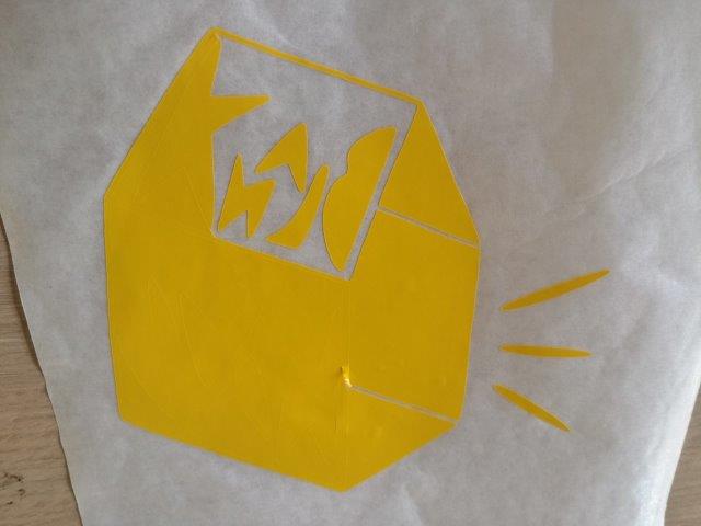
For cutting I choose the logo for my electronic music net label Blankhaus (check it out!) As I only had it in .jpg format I did a quick tracing on Inkscape.
First, open Inkscape and import the .jpg using Ctrl+i

After selecting a scaling the image I used the Shift+Alt+b command to trace the bitmap, this option is also available in the left click menu on the image. I kept the default settings and hit OK.

The trace is made and automatically grouped but placed above the original raster, just click and drag to see it.

Then I erased the raster and exported the image as a .png with Shift+Ctrlt+e, because Mods works with .png files

I decided to also save it as a .svg (vector) file.

We load the Mods software from the console with the command sudo fab, this opens a window where we select the type of file to load, the machine we are using, and the program.


The first step is to load a .png using the load .png button, next we check the settings for force and velocity in the right (we'll be working with the default settings as this is my first try).
The default settings goes as follows:
- force: 50
- velocity: 2
- diameter: 0.25
- overlap: 0.5
- offsets: 1
- error(pixels): 1.1
- intensity: 0.5

Once we have the image loaded, we press the generate path button.

The image (in blue) next to the .png is the cutting path the machine will follow during cutting. next, we just press send it! to begin the cutting.
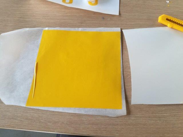
Once the machine finishes, we unlock the roll (using the lever) and cut the piece manually; then we use a special transfer paper that sticks to the vinyl. We proceed to peel the vinyl paper exposing the sticky side and continue to peel the excess to show our design. We can do this with the help of a cutting knife for the small details. The default parameters perform very good.
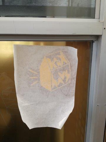
Now we can transfer our design to a surface, I selected a glass panel on the FabLab as I originally planned to make a sticker for my laptop but forgot to scale de .png, so the design was too big.


 <
<

