Slide and Video
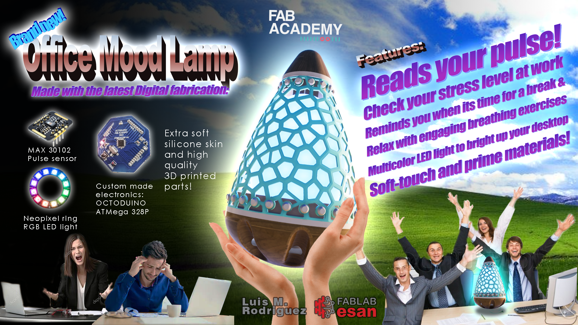
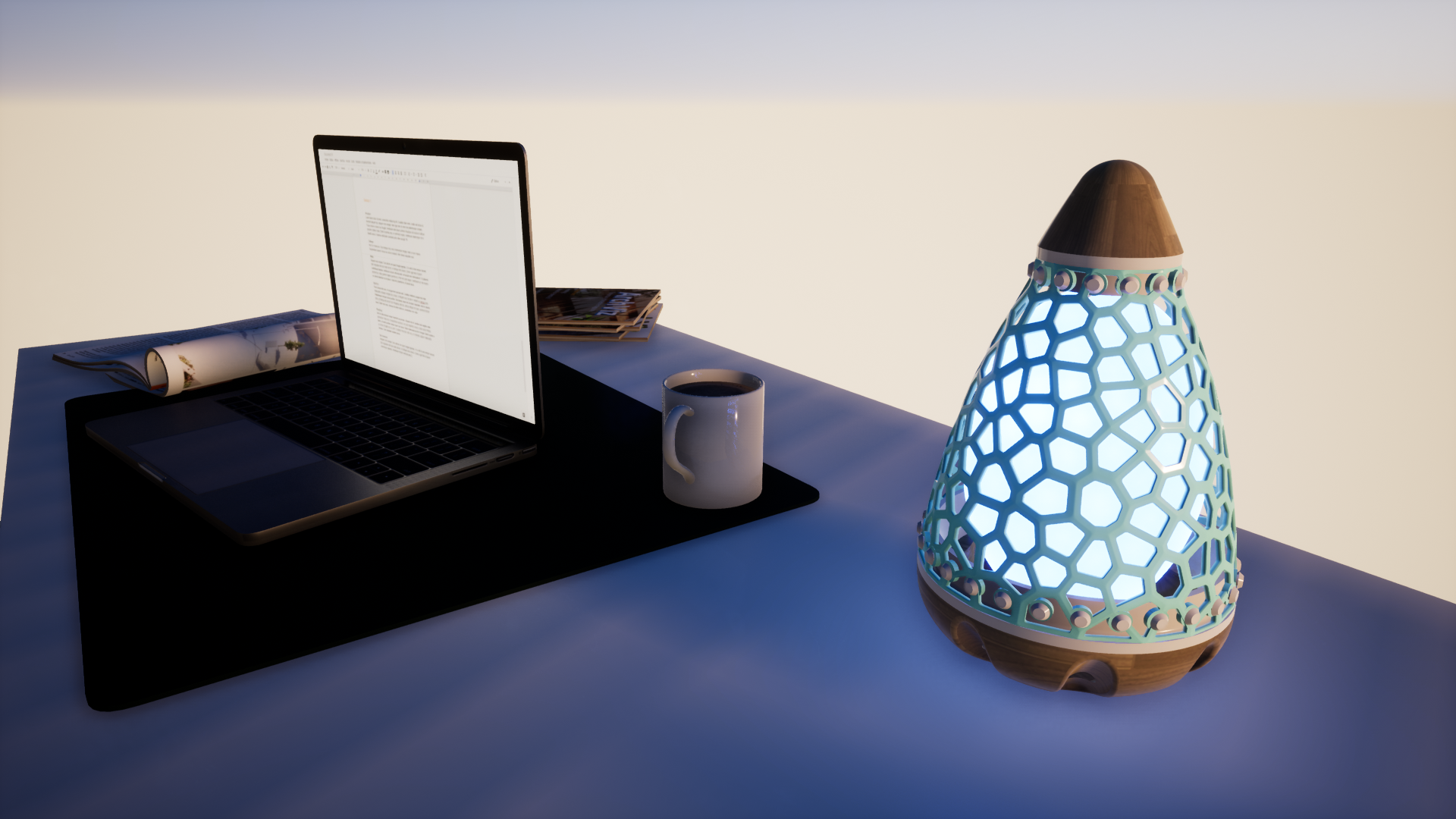
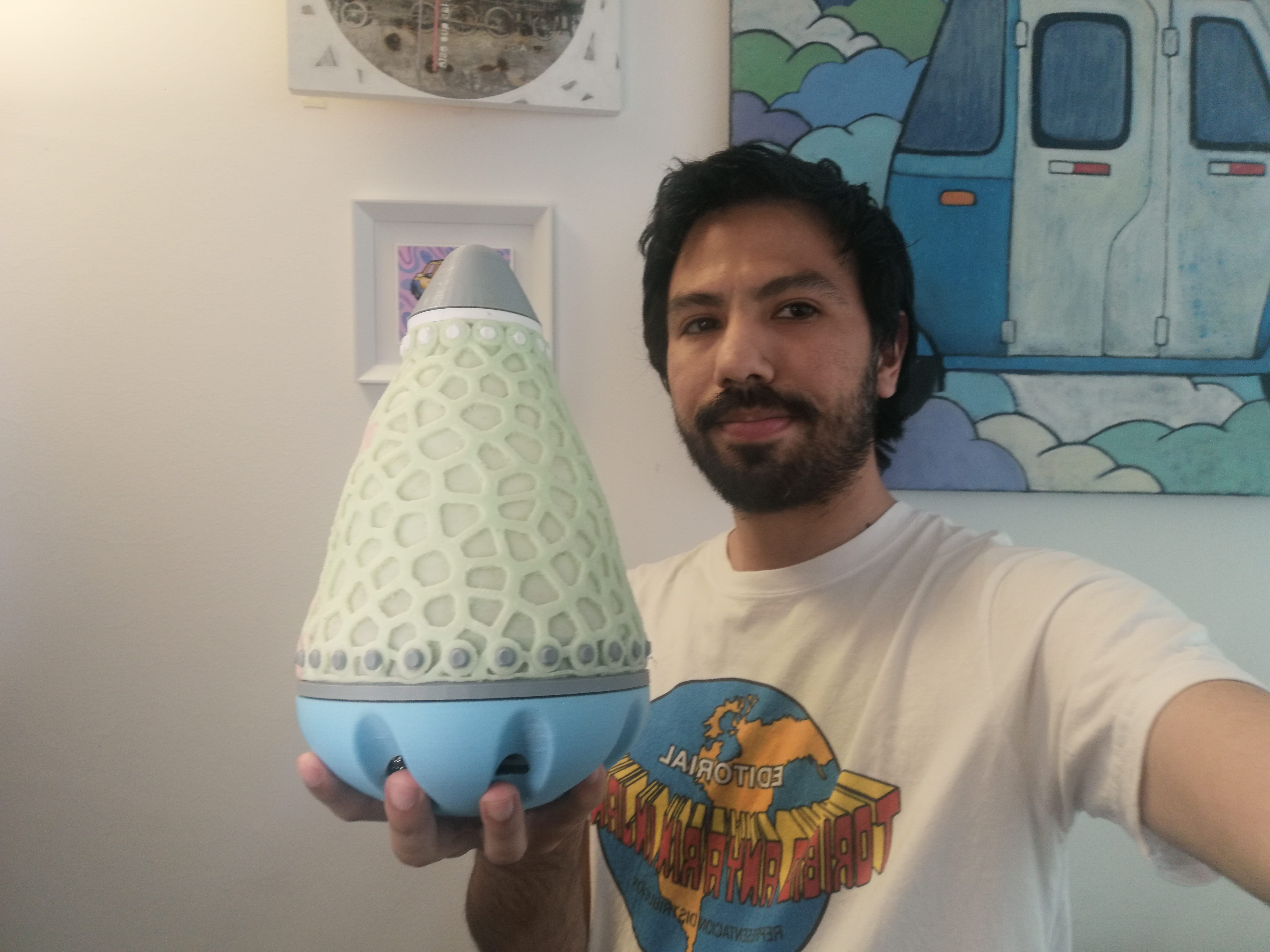
Digging that retro office look? The Office Mood Lamp is for you!.
Project development and Final Project Requirements
The complete answers to Project development and Final Project Requirements Q&A can be found in this link.
The problem
Stress is a growing health issue, long working hours in an office environment can affect people’s health. This could be avoided if stress signs would be easily readable.
The idea
A lamp that could be placed in the office desk that can monitor stress levels in an office environment.
This will work by reading biological signs of stress (like pulse, heart rate, respiration, transpiration, ocular movement, etc.) of an employee and display it in color code (ex.: blue for relaxed gradually turning red if stressed); allowing them to be conscious about increasing stress levels during the day and the need for taking a short break or as a reminder of taking an active break. ;)
The lamp will also have a pulsating movement (inflate and deflate) to synchronize with the office worker state and work like respiration exercises to breathe in and out.
Input data: how to measure stress?
As the lamp would be connected by USB to the PC, it could continuously be monitoring stress signs without being invasive by using the PC webcam. In this configuration, the processing of the facial expressions would be made by the office computer, and the lamp would only display these data and allow for interaction. Another configuration would be having a high-resolution camera embedded on the lamp.
There are several research papers linking stress and facial expressions data from video. (see bottom)
On the other side, a more interactive way to measure stress can be made with a pulse sensor, this device could be embedded to the base of the lamp to make measurements at any given time indicated by a visual cue.
Heart rate and more specific heart rate variability is one of the most robust measures of the stress response. The interval between heartbeats naturally varies, to the extent that the heart rhythm during a single breath cycle (of one inhalation and one exhalation) can change by 10 to 15 beats per minute.
But when someone is in a distressing or scary situation, the autonomic nervous system activates the fight-or-flight response, which reduces the variability in the interval between heartbeats. A stressed-out heart, for instance, may only vary by two beats per breath cycle.
However, the combination of the two methods could be possible.
Swarm capabilities
Imagine entering an office space with many people working and with one look one can figure if it is a relaxed or stressful day depending on the dominant color.
The lamp or several lamps placed in an office will show this as a color cue, save this data and share it with an app or software to monitor the stress levels of the office environment daily. This will help identify the stress triggers and the status of teams, or the general mood of the workforce.
The design
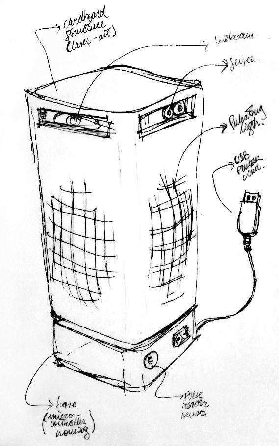
The original sketch design (see above) for the Office Mood Light Lamp was a rounded square tower, that holds the electronics and actuator components at its base, the light feature in the middle, and the sensors on the top.
But the whole concept of the lamp is to be conscious of the stress level in the office environment and to mitigate the stress, this tower shape seemed a little bit rigid and boring.
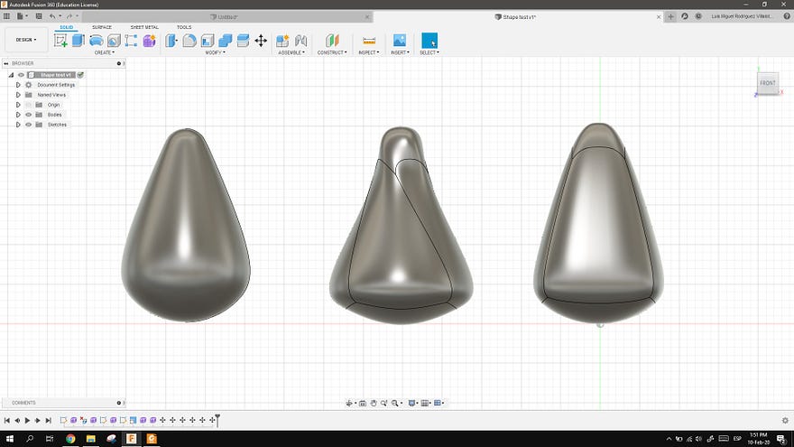
To find a less boring shape I took inspiration from a fidgeting toy I use while working that’s called a Mighty bean, this is a pill-shaped (rounded base and top) plastics toy that holds a ball bearing inside making it move like a roly-poly doll.
Also, because Fidgeting helps reduce stress levels and can improve concentration, so it seems natural that an anti-stress lamp should move and be gentle to touch.
To see more of the design process and modeling visit Computer-aided Design week.
Testing the concept shape
I did some quick tests to see if this shape would work by making basic shapes in Fusion 360 and then using the built slicing software to cutting it with the laser.
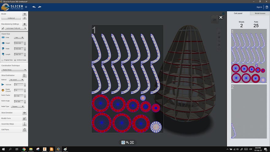
This is the shape assembled. I secured it with tape because I used the wrong material thickness and the press-fit wouldn’t work. whoops!
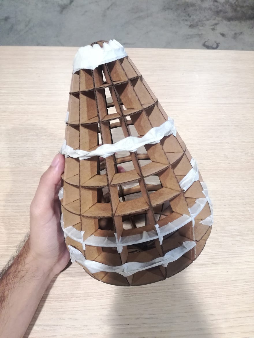
Here’s the first test for the swinging movement of the shape (It’s not the best because it lacks a heavy bottom, but you can get the idea)
Designing the Base
The base design was made in Computer-aided Design week.
Designing the Middle piece: Rings and flexible skin
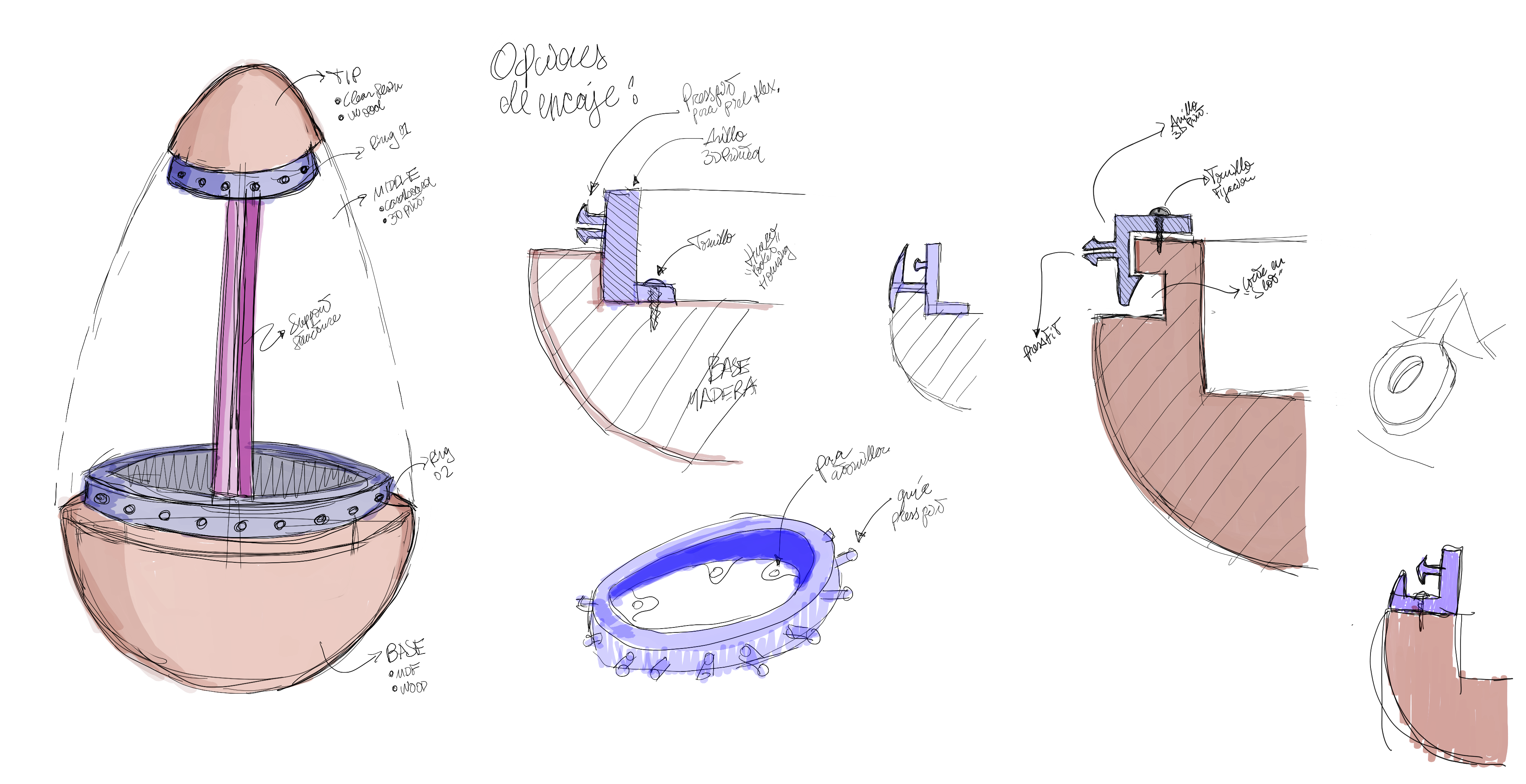
After the base was completed, I decided to tackle the middle part of the device, this is composed of 2 rings (base and top rings in blue), a central column (in light purple), and the flexible skin that is not shown in this sketch but it’ll cover the shape between the base and tip.
This sketch shows different options for the base ring and how could be attached to the base. I later decided it would work best just by screwing it to the base lip and attaching the flexible skin to the rings with press-fit buttons.
The flexible skin will be a sort of 3D printed mesh of flexible filament, this will allow the device to make the pulsating movement expanding and contracting. The mechanism that will act will be designed later.
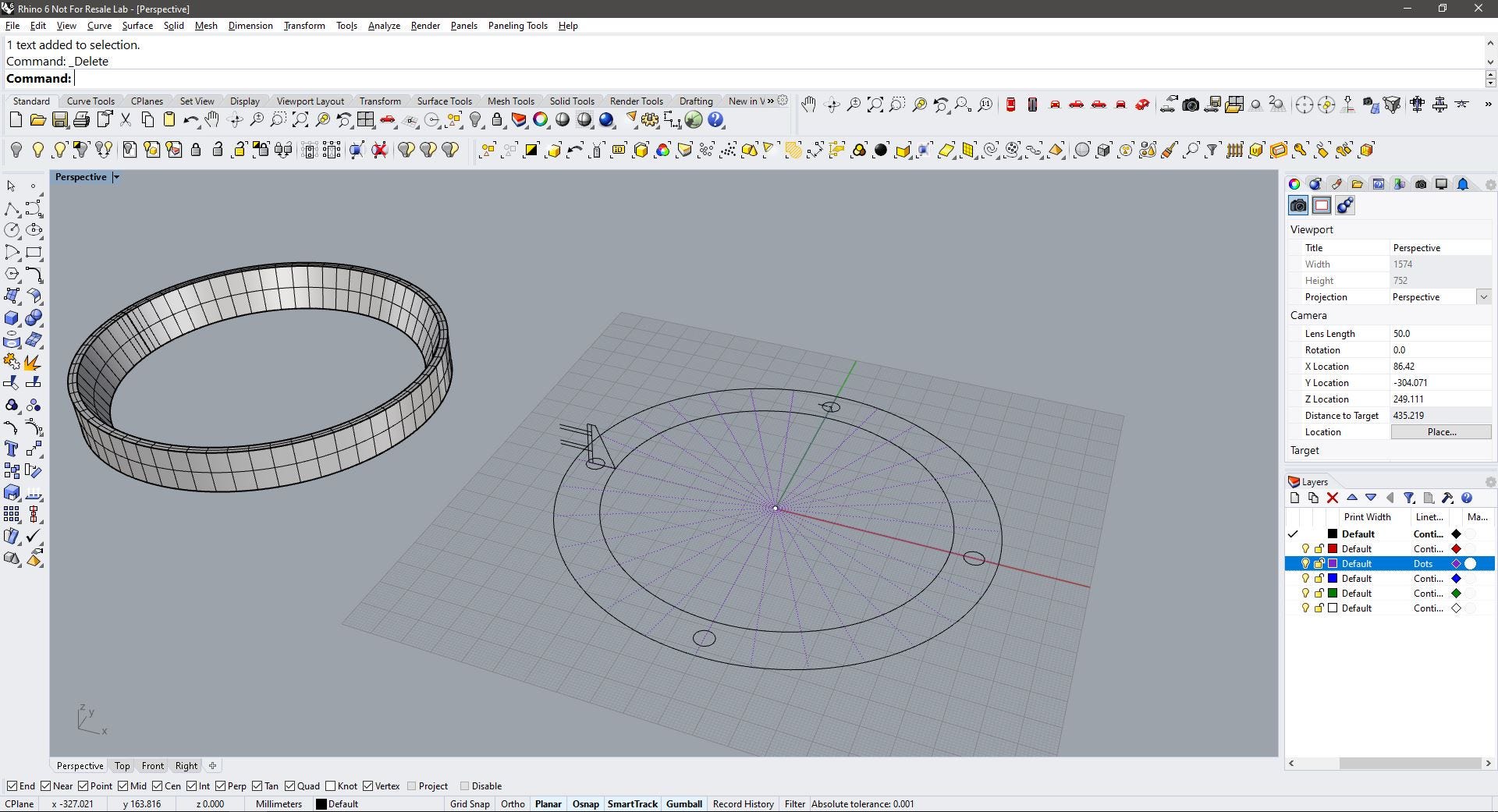
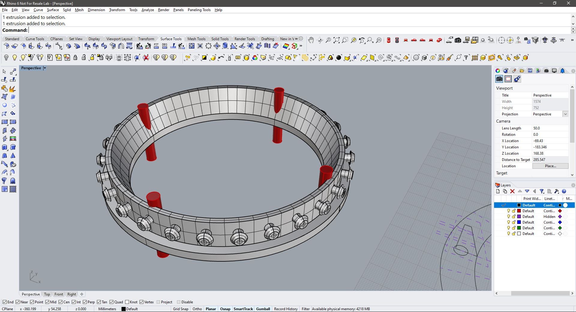
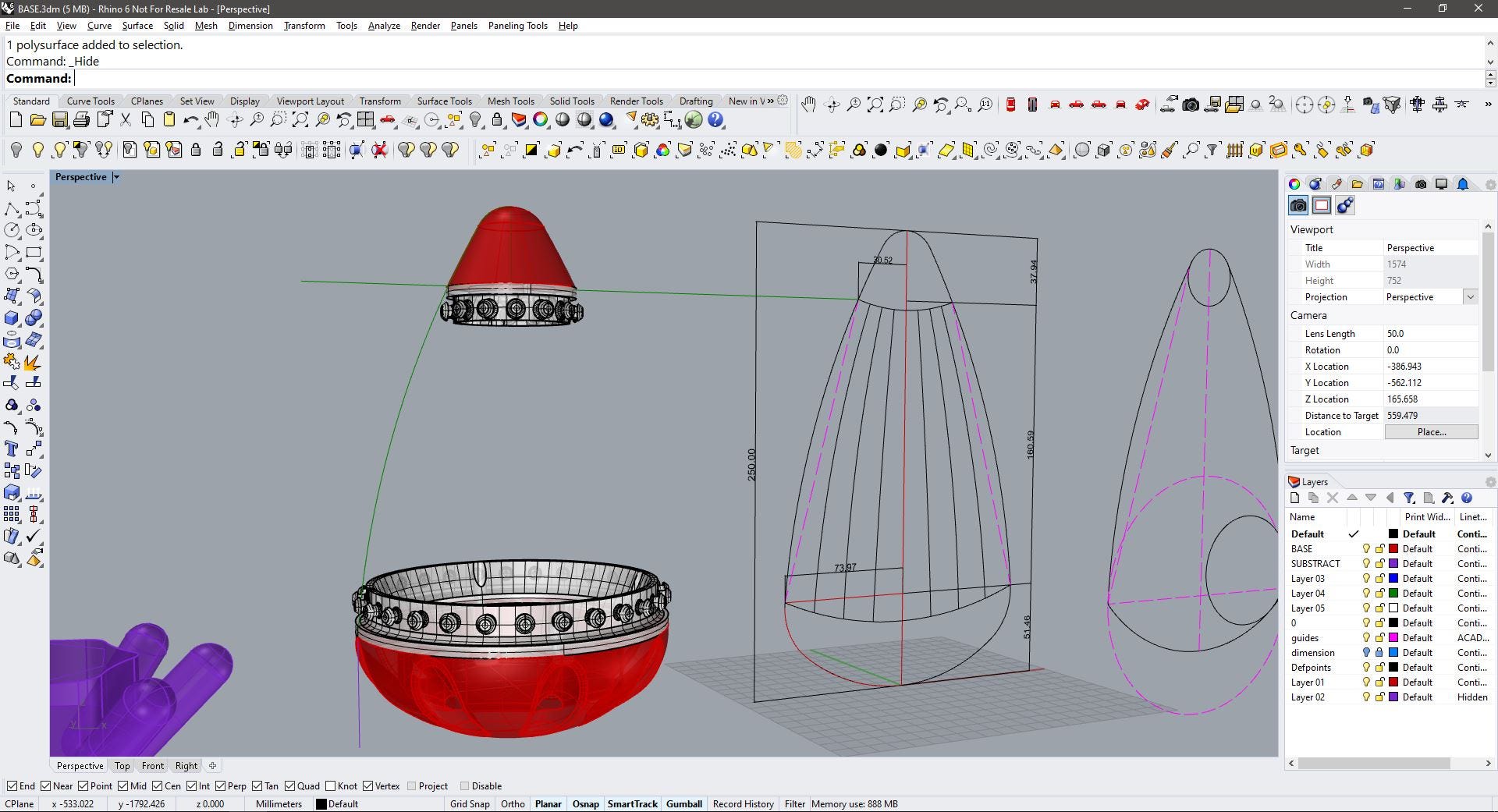
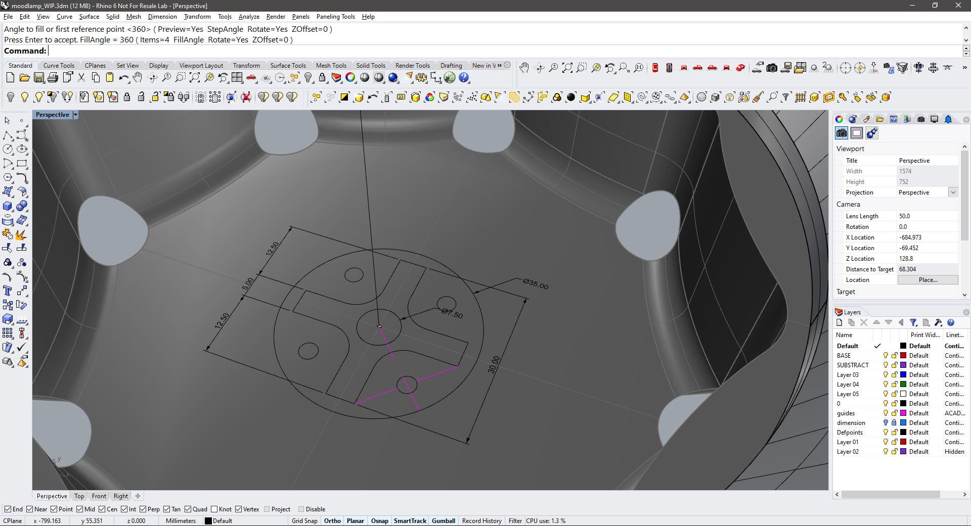
The first step is to design the base ring. As I already designed the shape of the base I took some reference measurements from the Rhino file (See: Computer-aided Design week for the files)
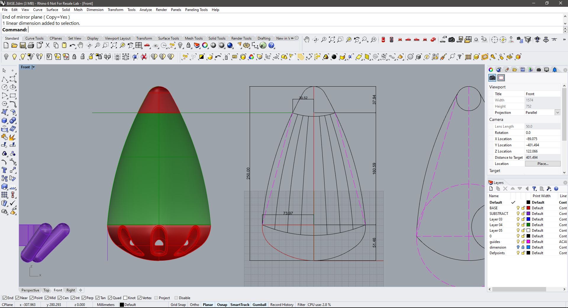
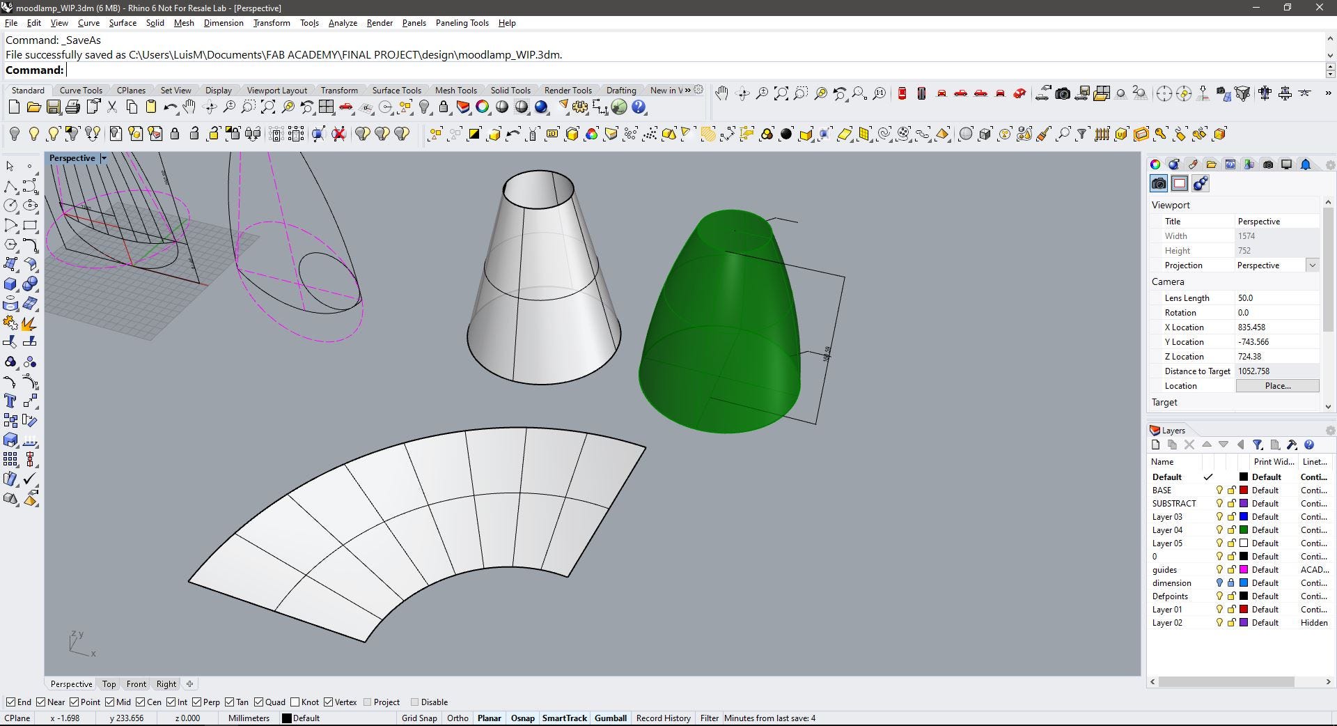
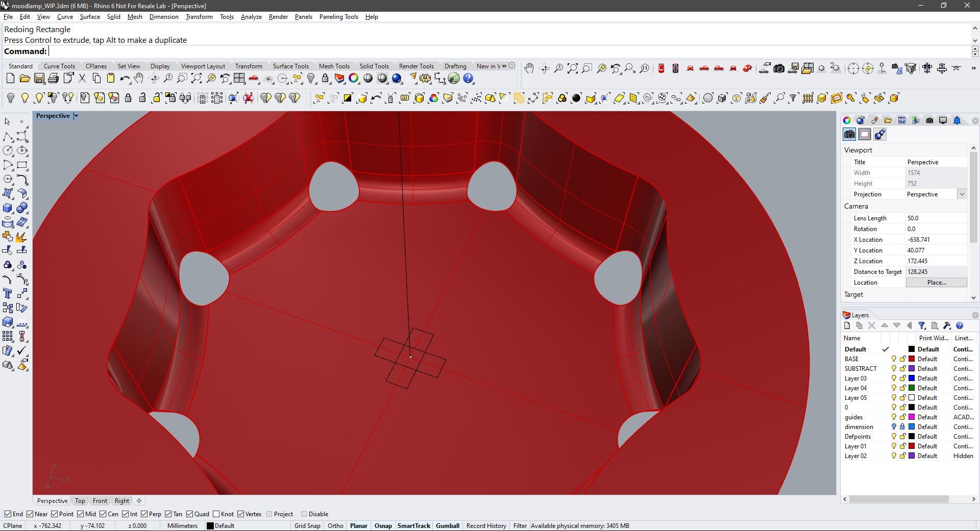
Then, I isolated the middle part, this is like a truncated cone shape, but it slightly rounded at the walls, not an important issue for now, as I will be only using the bottom and upper diameters for the rings.
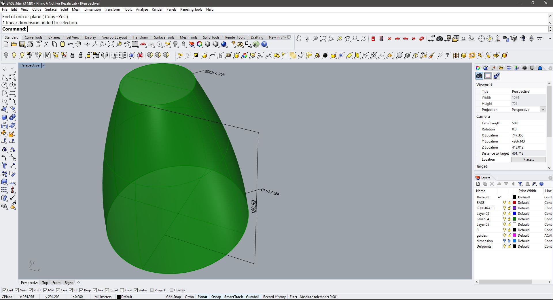
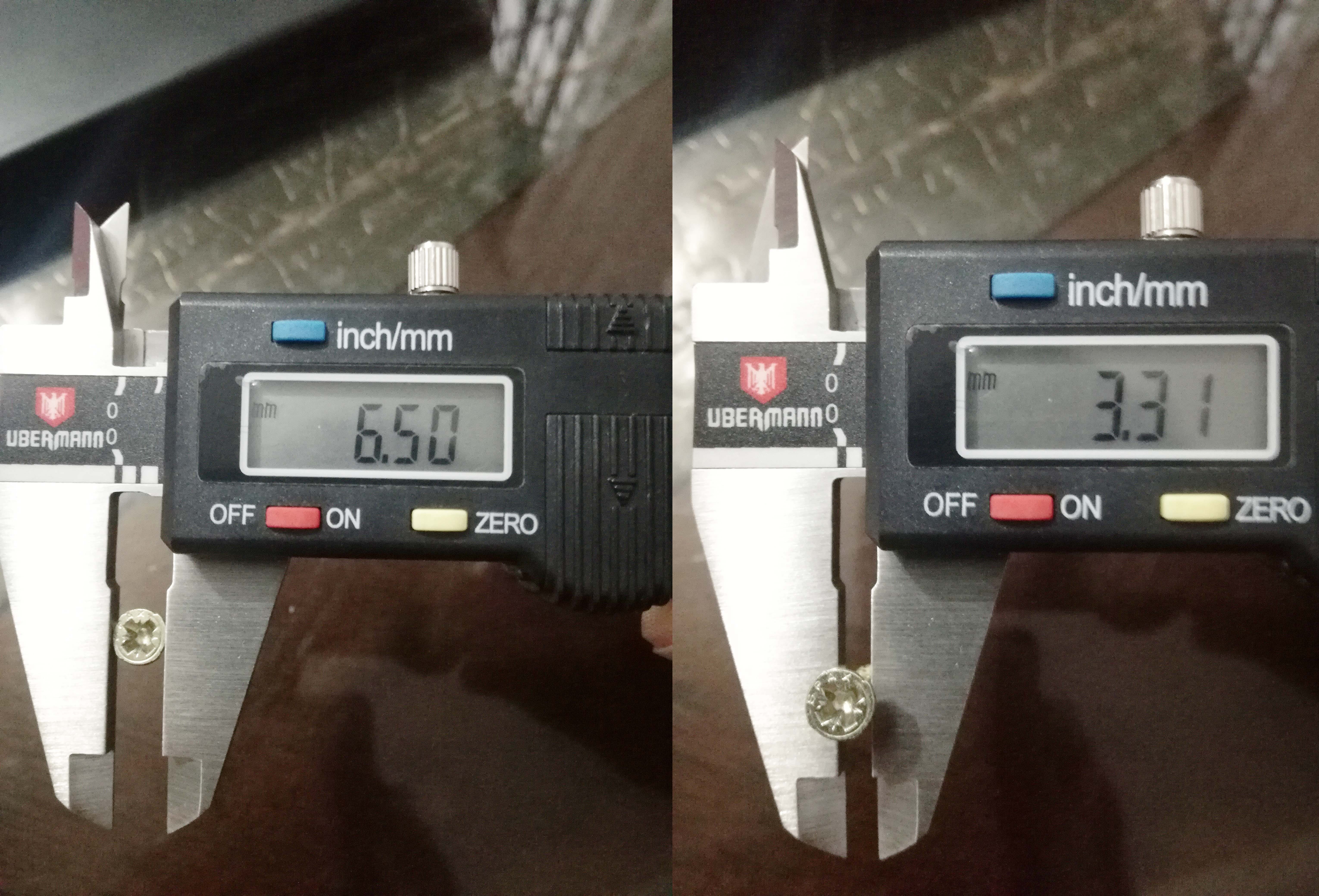
It began with a circular shape (based on the bottom diameter) and an inside offset of 15mm, 4 circles of 6.5mm in diameter that will make the holes for the spax screws.
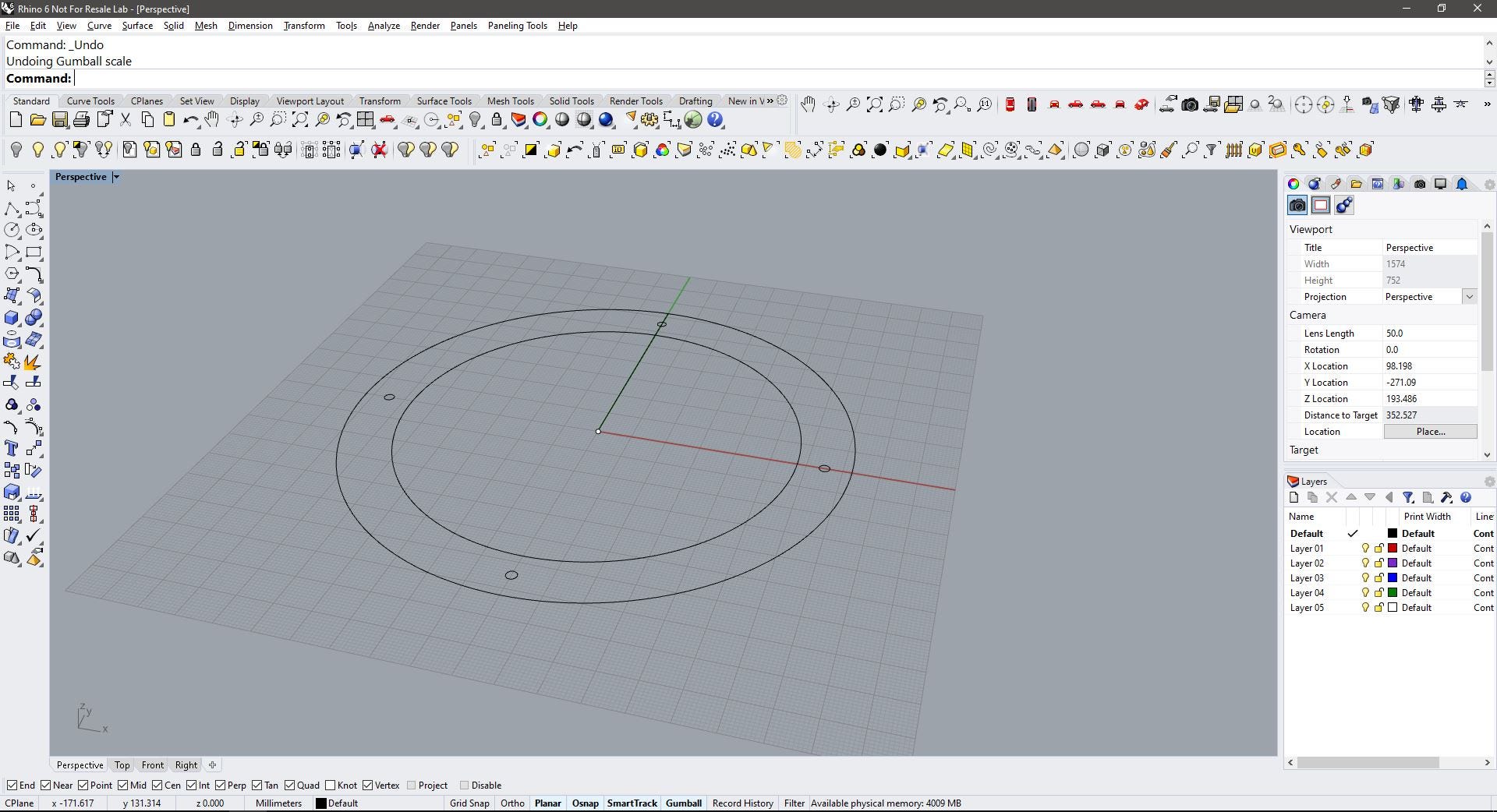
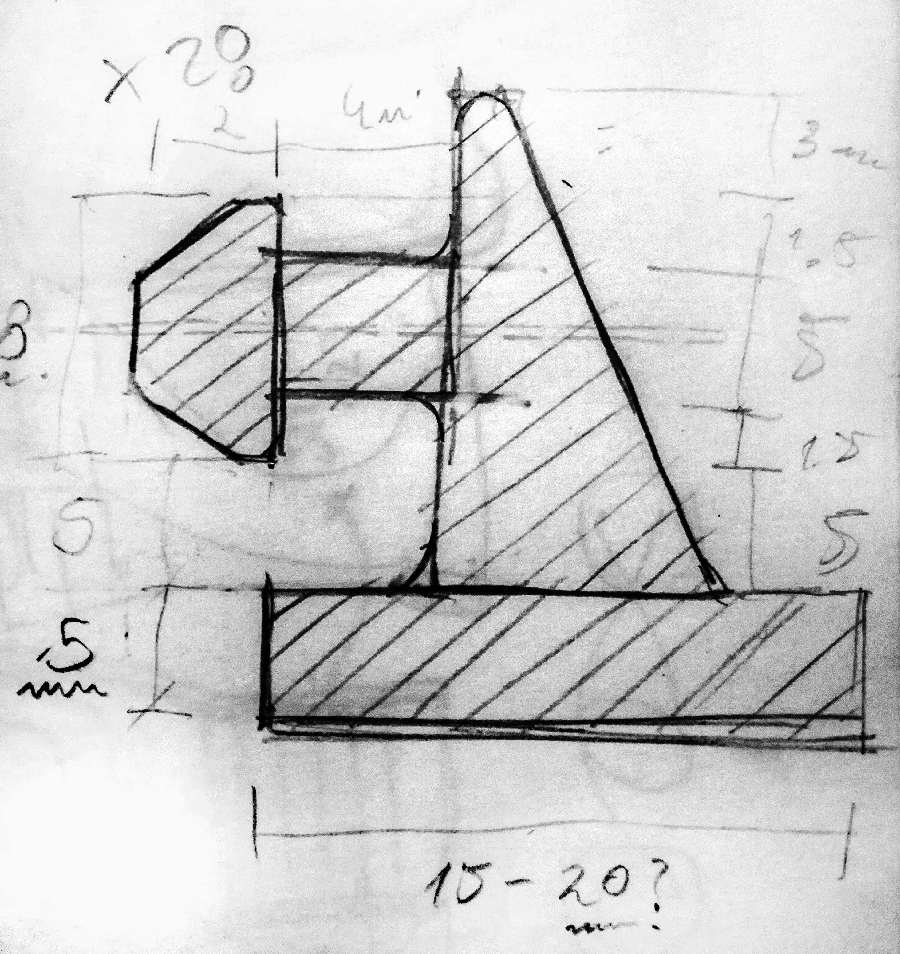
Next, I traced a shape that will revolve around the circle, this will create the inner wall of the ring, and will support the press-fit buttons. I made a quick sketch of how it would look like in a section. Notice how the buttons protrude beside the ring.
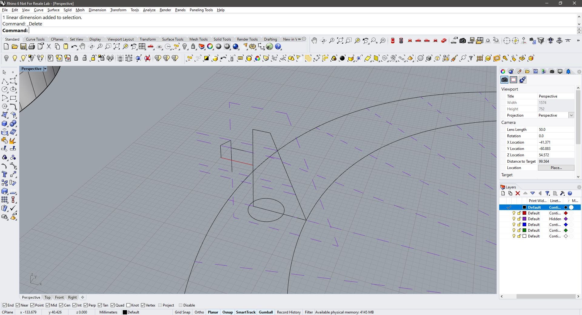
I moved the volume to the side to keep working with the template for the other components.
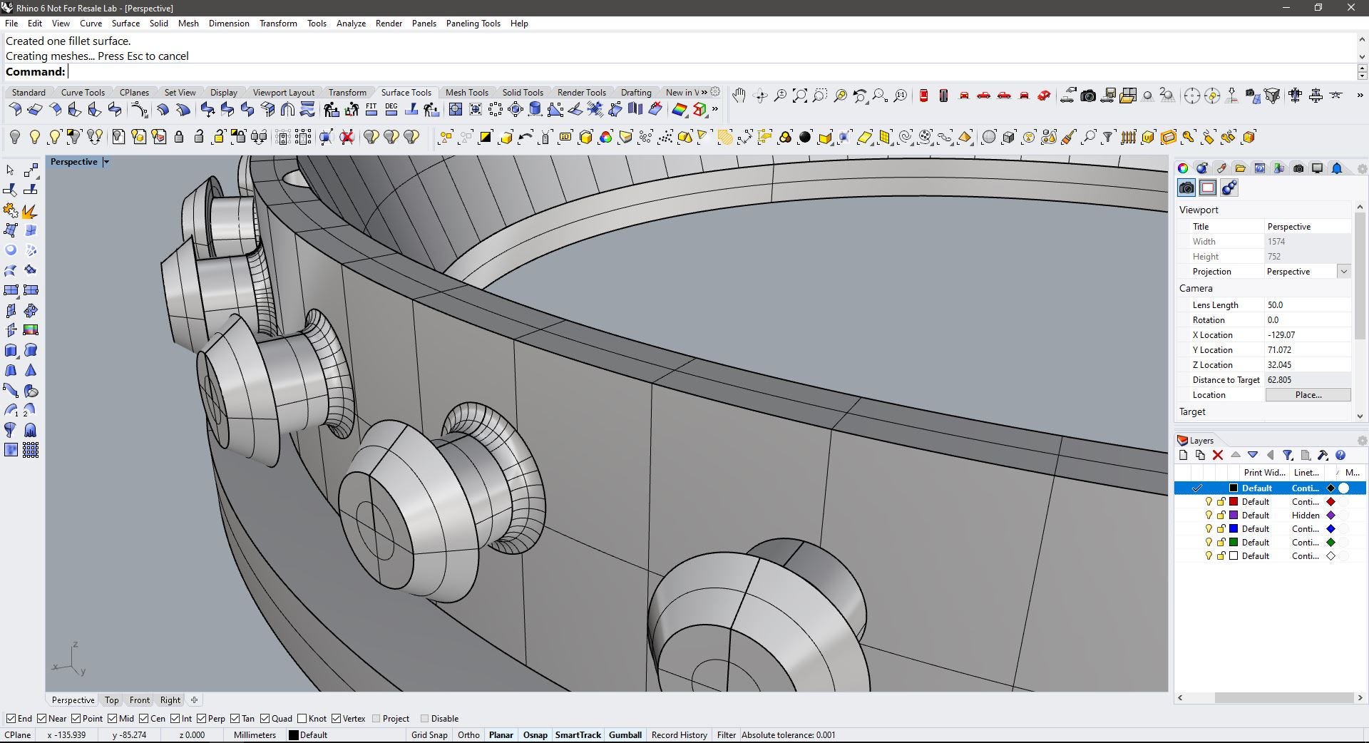
After the wall of the ring was formed, I started to work on the buttons using the same template and the revolve around axis command. This shape will repeat around the circle attached to the wall.
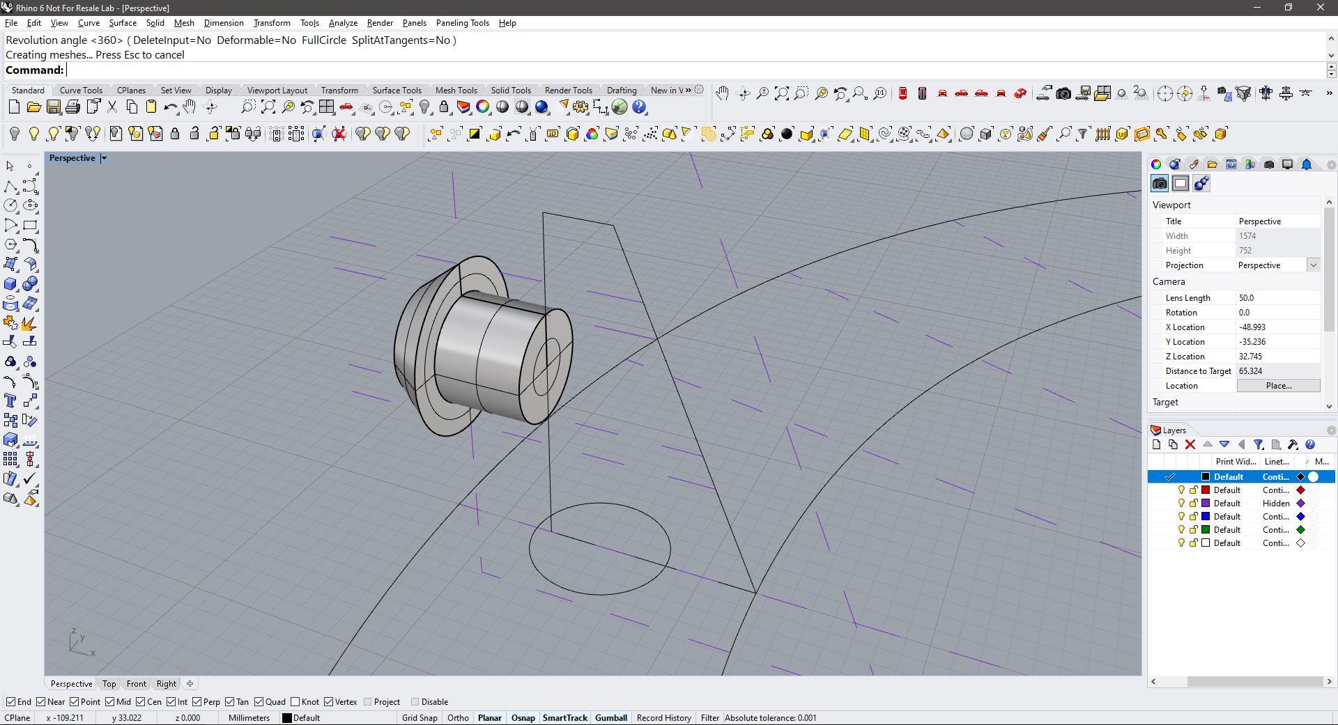
The circular pattern was created using ArrayPolar command and taking the center of the circumference as reference. The buttons repeat 28 times, so, 7 buttons every 90° degrees. Not too tight not too loose.
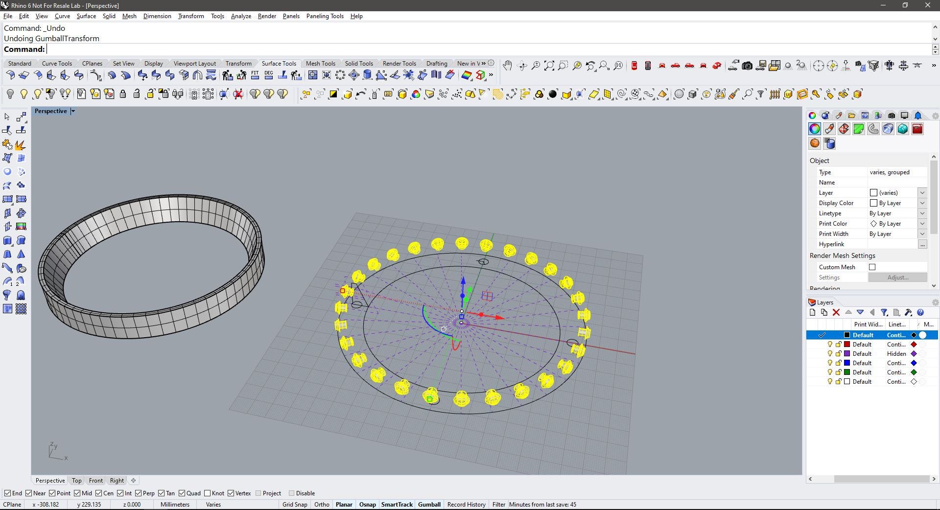
Here is a view of the buttons next to the wall. notice that because the wall is circular, and the button part that attaches to the wall is flat, there’s an additional operation needed to join these two components.
The final step for the ring is the lip, this is made by extruding the two circles that we created at the beginning by 5mm.
Then came the holes for the screws, this was made extruding the 4 circles as cutting solid. The position was too close to the outer side of the wall so little modification was made, moving these cylinders 2.5mm to the inside
After a boolean difference operation, the first part of the holes is created. notice that first we only cut the wall to make room for the screw heads.
Then I scaled the cylinder about a half to make a second cut, this time on the base of the ring to make the screws go through.
To create the join between the buttons and the wall I created a fillet of 2mm. and then joined the geometries.
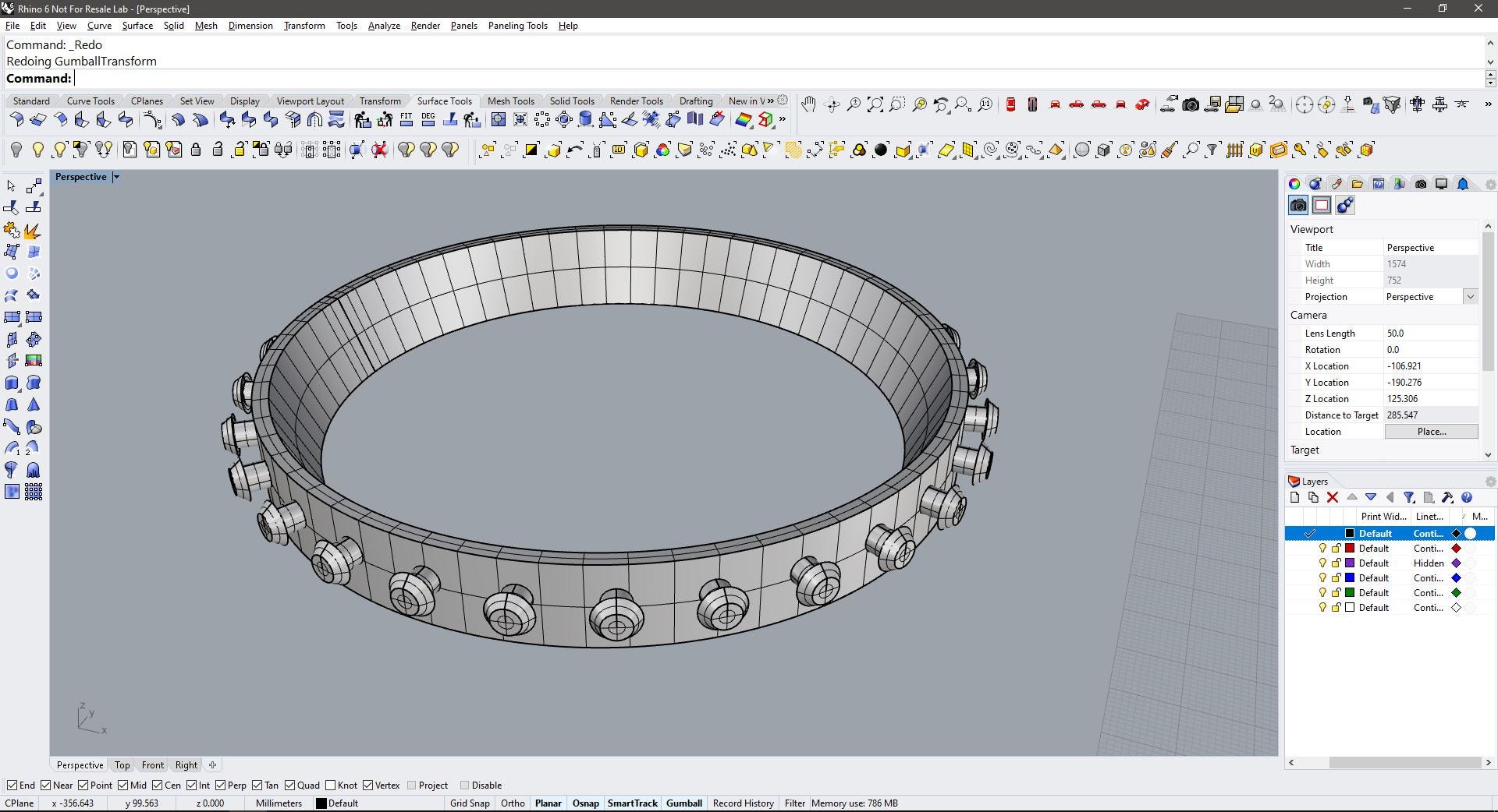
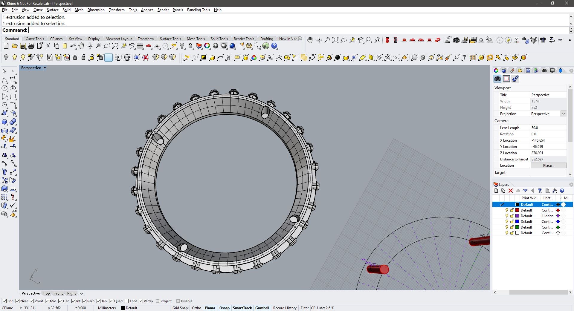
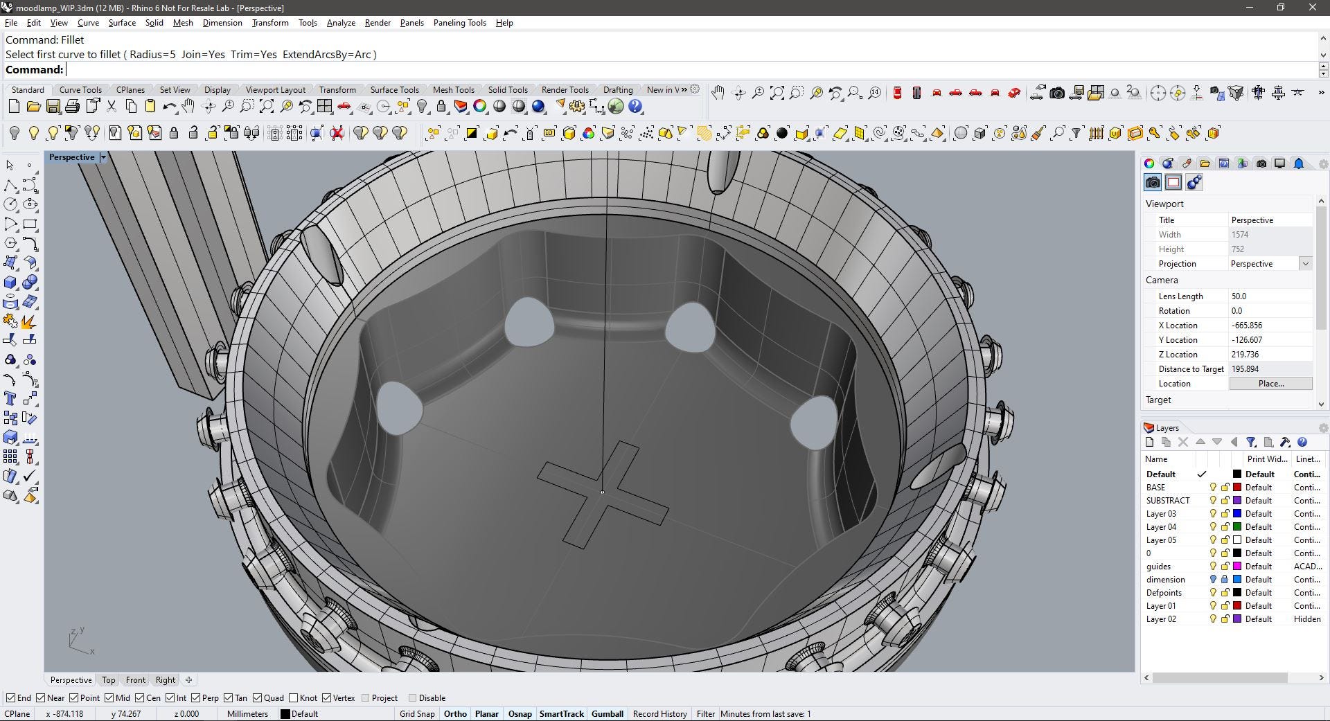
This is the finished ring, some additional fillets were made between the bottom and the wall.
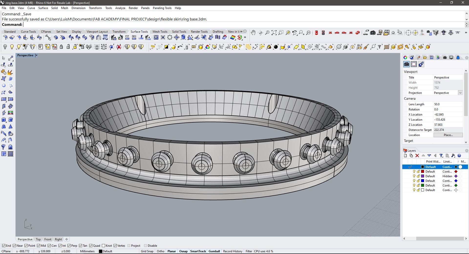
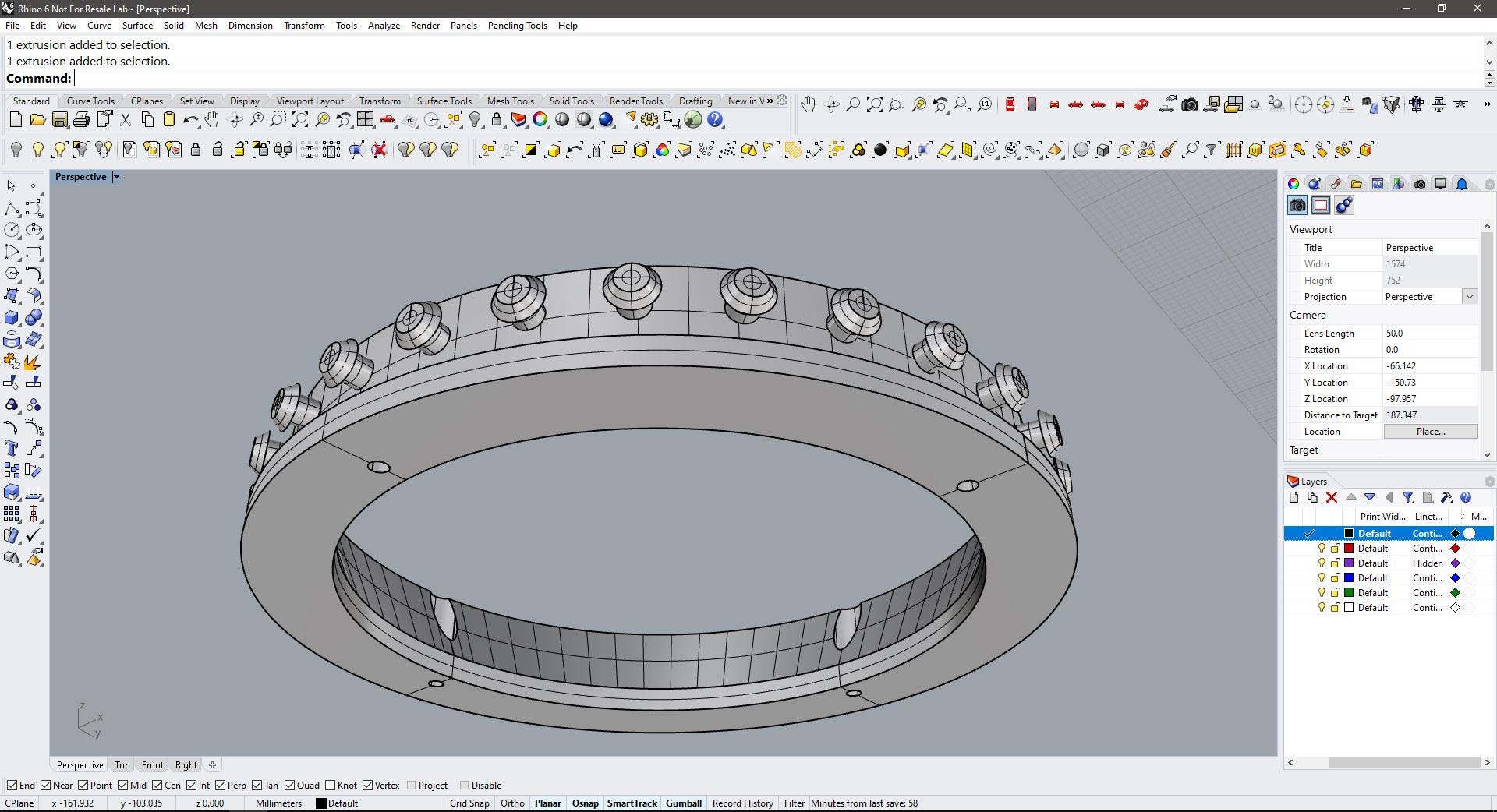
This is a view of the ring attached to the already modeled base.
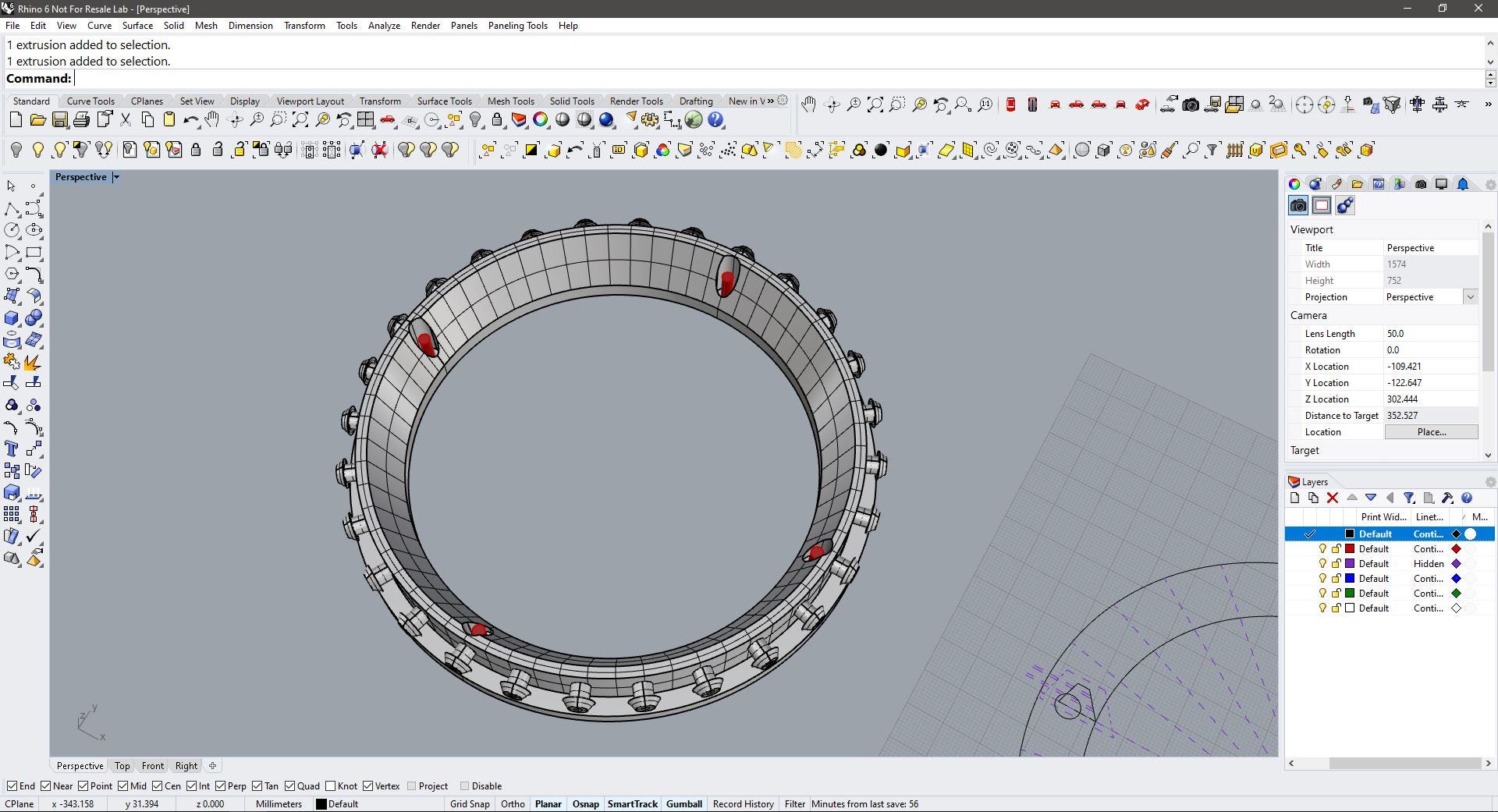
I modeled the top ring using the same technique, but this time the number of buttons created is 14, the wall is narrower and only two screws are joining the ring and the tip cautiously placed to not interfere with the buttons. This ring would be placed upsidedown.
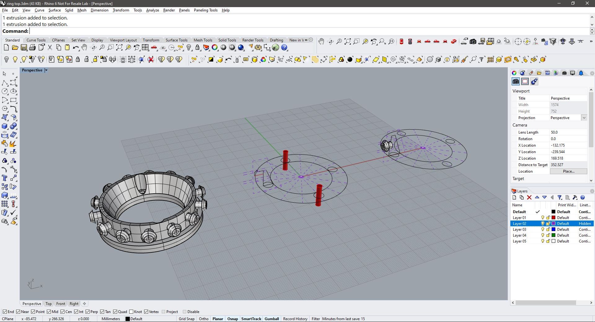
This is the model with both the rings. notice that the green line (that follows the original shape) does not fit with the buttons on the top as with the buttons of the bottom, maybe I would change the shape of the top ring varying the orientation of the buttons with an angle and not parallel to the base.
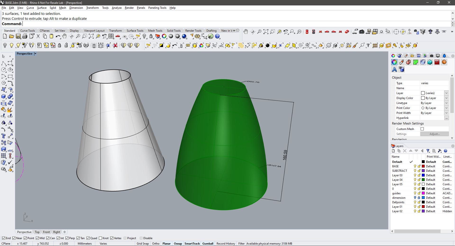
The next phase is to make the flexible skin (green shape) that will attach to the rings, as this shape is rounded (its not possible to flatten a curved surface accurately) I made a truncated cone using the top and bottom diameters.
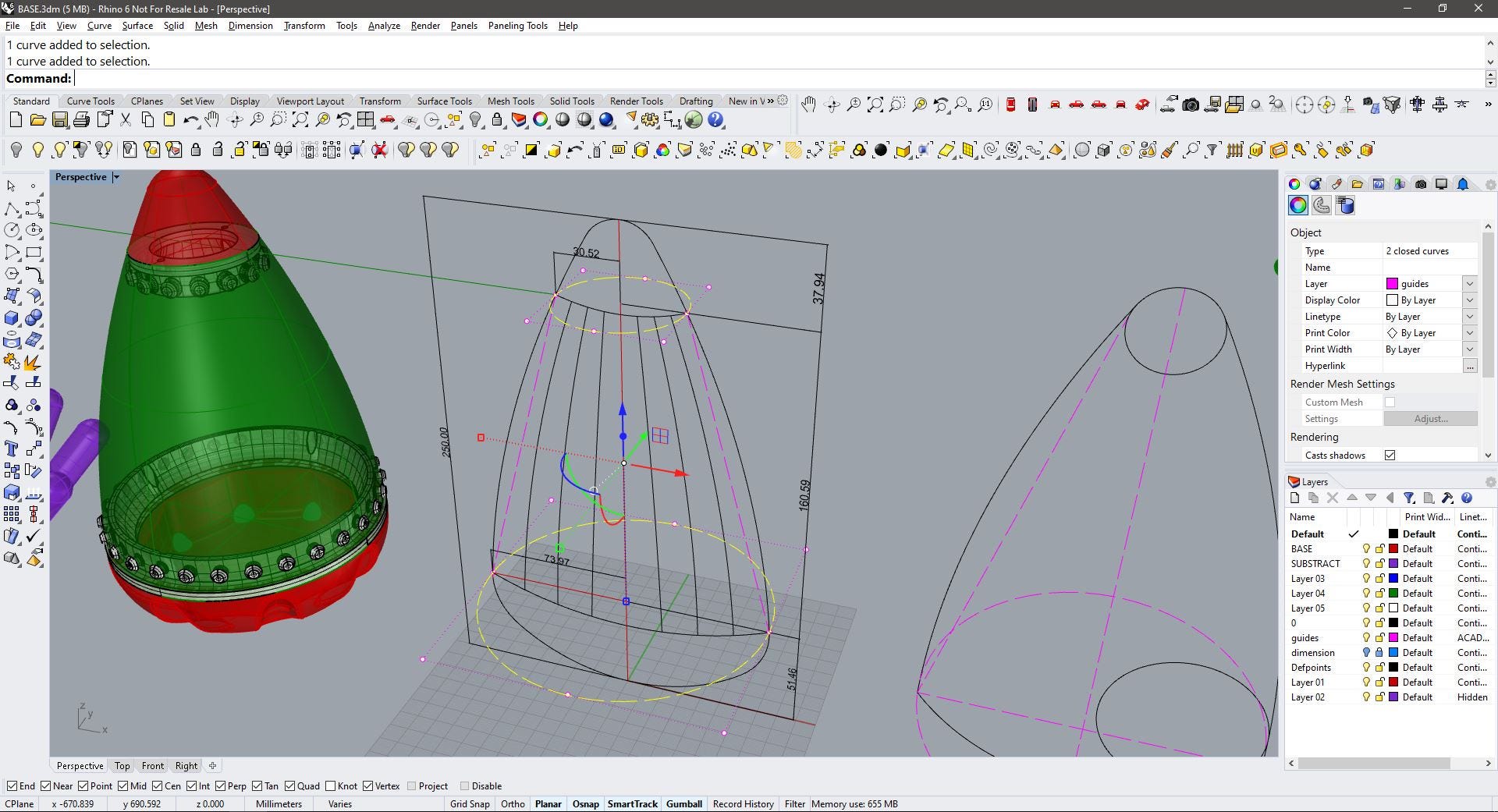
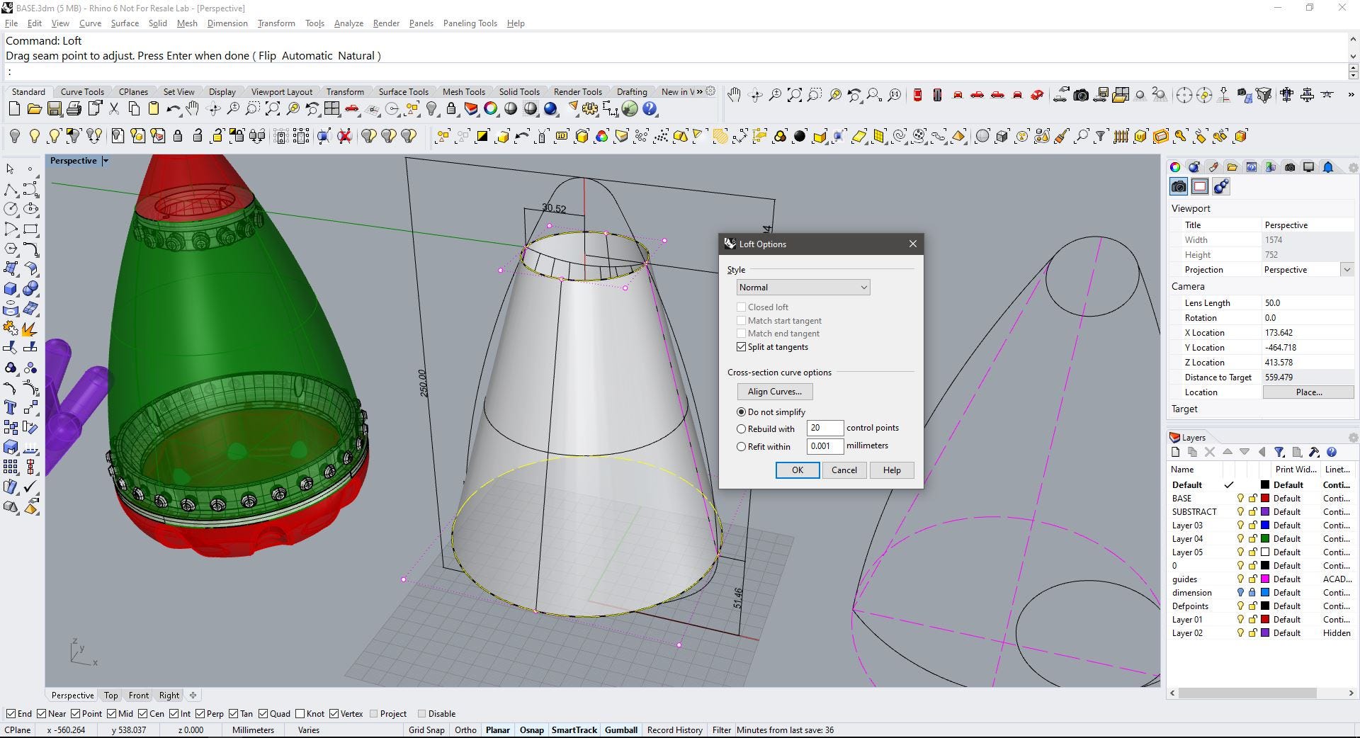
Here you can see the two surfaces (actually, the green shape is a solid). I forgot to subtract the height of the rings(10mm for both) from the height of the cone, so I corrected it in the next step.
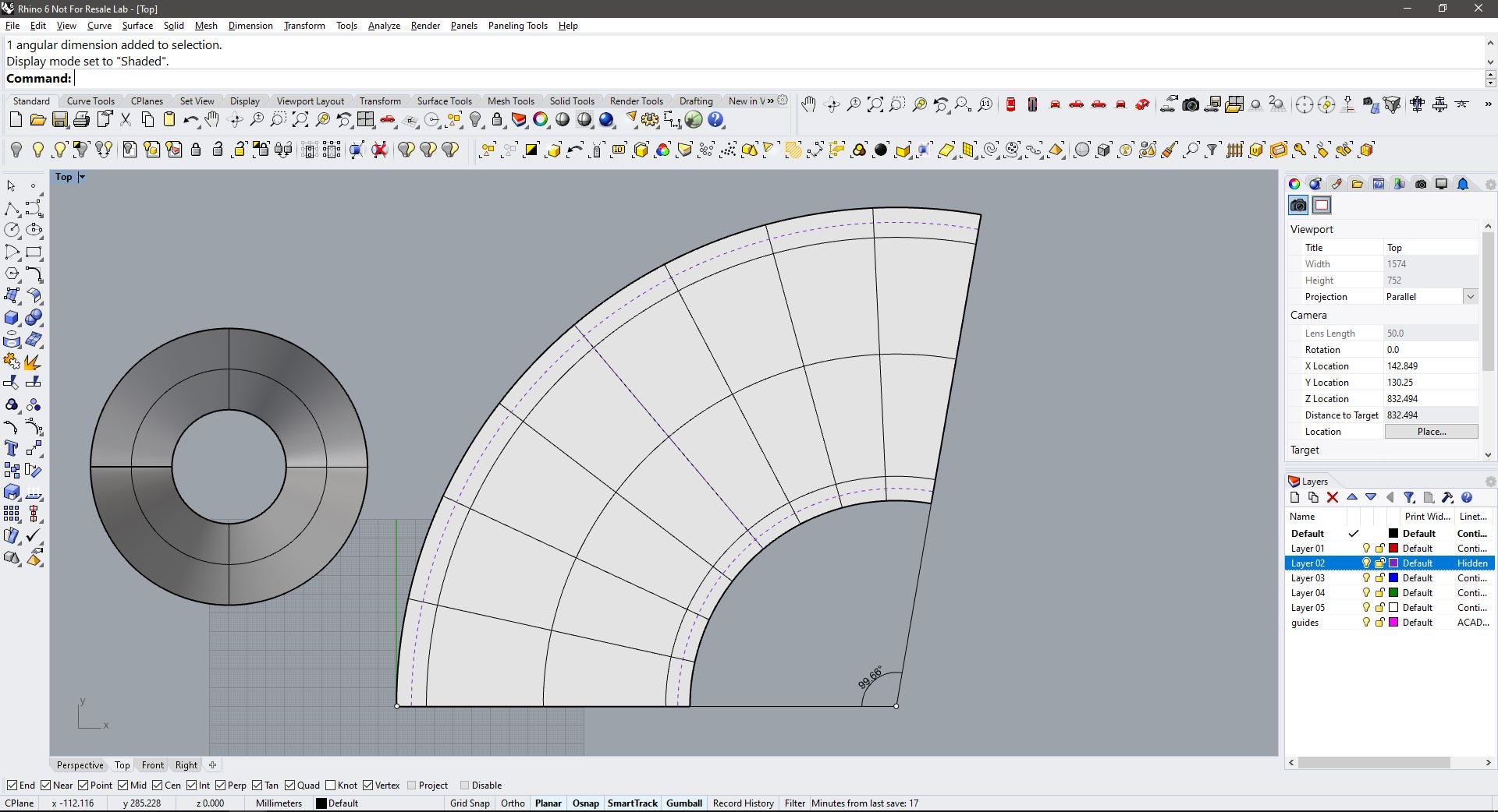
Fortunately, Rhino has a command that allows unrolling surfaces to planar objects, this is UnrollSrf. Using this I got a flat piece for the truncated cone.
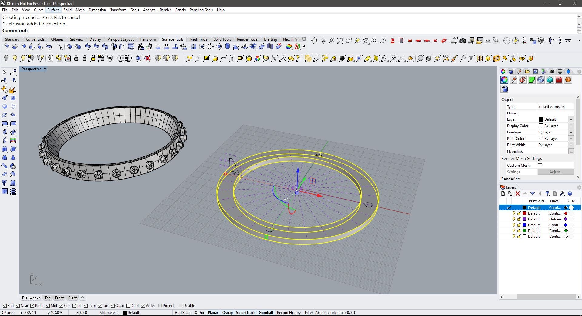
I made an offset of both sides of the curves, this will be the section where the holes to fit the buttons will be created. there’s a dotted centerline as a guide. I also marked the angle to make the polar array.
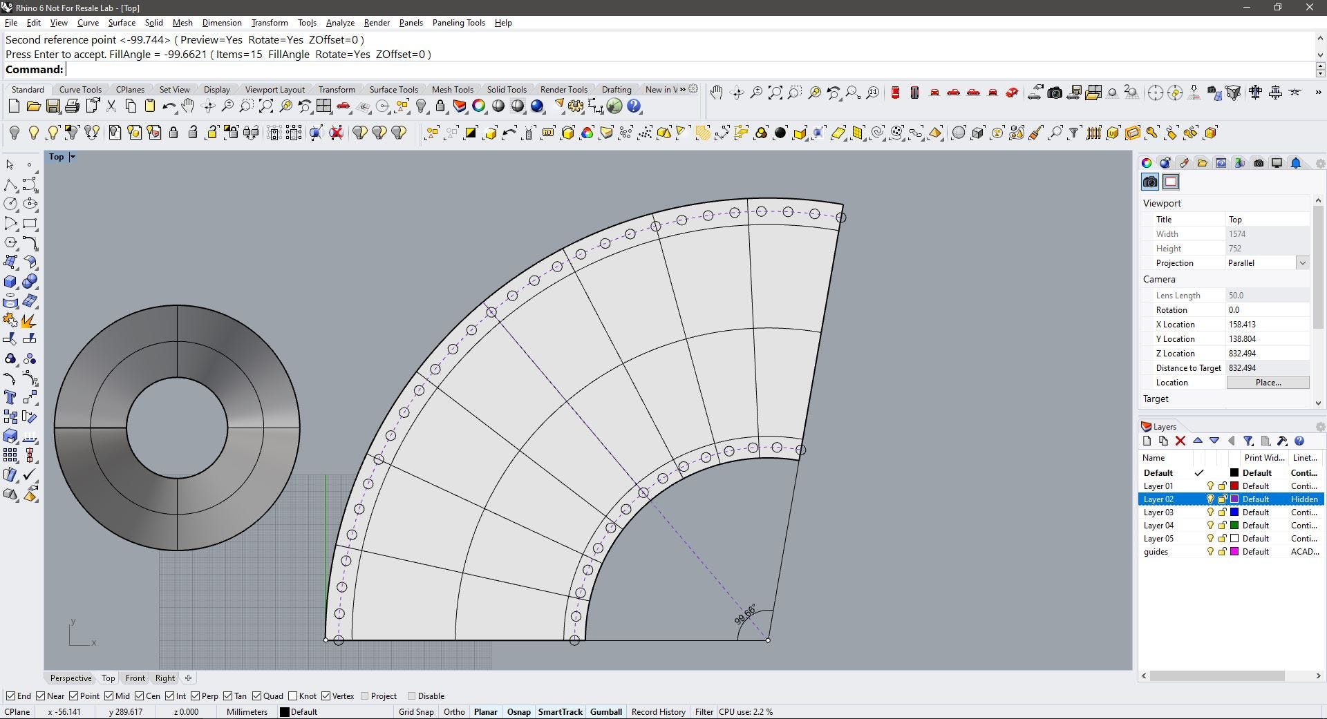
Using the ArrayPolar command I placed the holes, it is important to notice that when making the bottom holes (exterior curve) the polar array should be made with 29 repeating circles (28+1) as the two placed on the edges are two half of one circle. The same is considered for the top holes (14+1).
We can check that this is the correct placement as the lines in the cone intersect a hole every 7 elements.
My first idea is to have the holes in strap-like sections, this will add stability to the holes and hopefully made them more durable to tear. So the skin pattern should go between these bands.
I decided it would be faster to 3D print a flat shape for the skin, and also easier to put in place or remove during testing, but not yet decided the actual pattern on the skin, so I’ll be trying different approaches on render. (more on the skin later!)
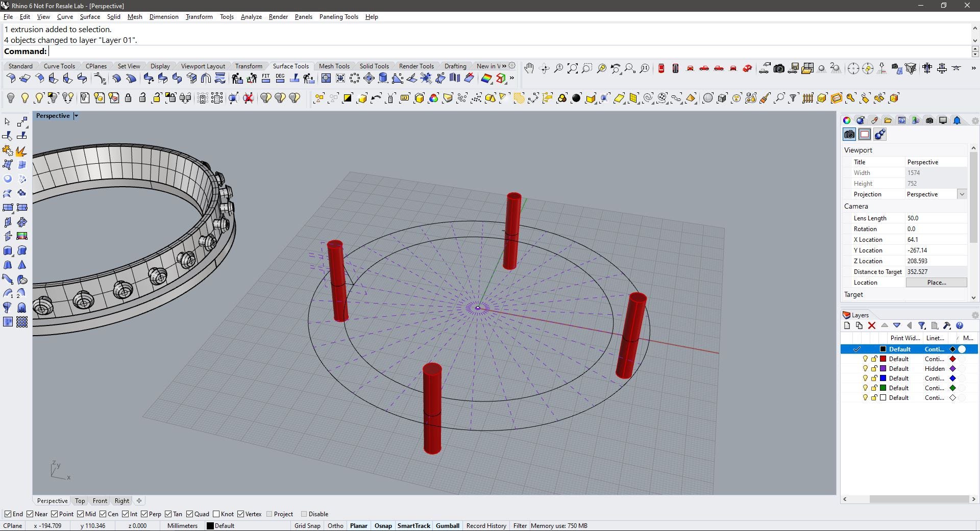
My first choice for joining the base and the tip (both might be made in wood) was using a central column, this piece will screw to the pocket on the base and to the tip. This will have a cross-like shape (inspired by the Barcelona Pavilion) and be hollowed to make room for cables in case I’ll choose to have LEDs on the tip or some other electronic component. Maybe a sensor?
I tried a simple cross shape but was not happy with the result as this looked too chunky and too unstable.
For the second attempt, I extended the section of the cross. the base now looks gray because the component it’s locked to draw on it.
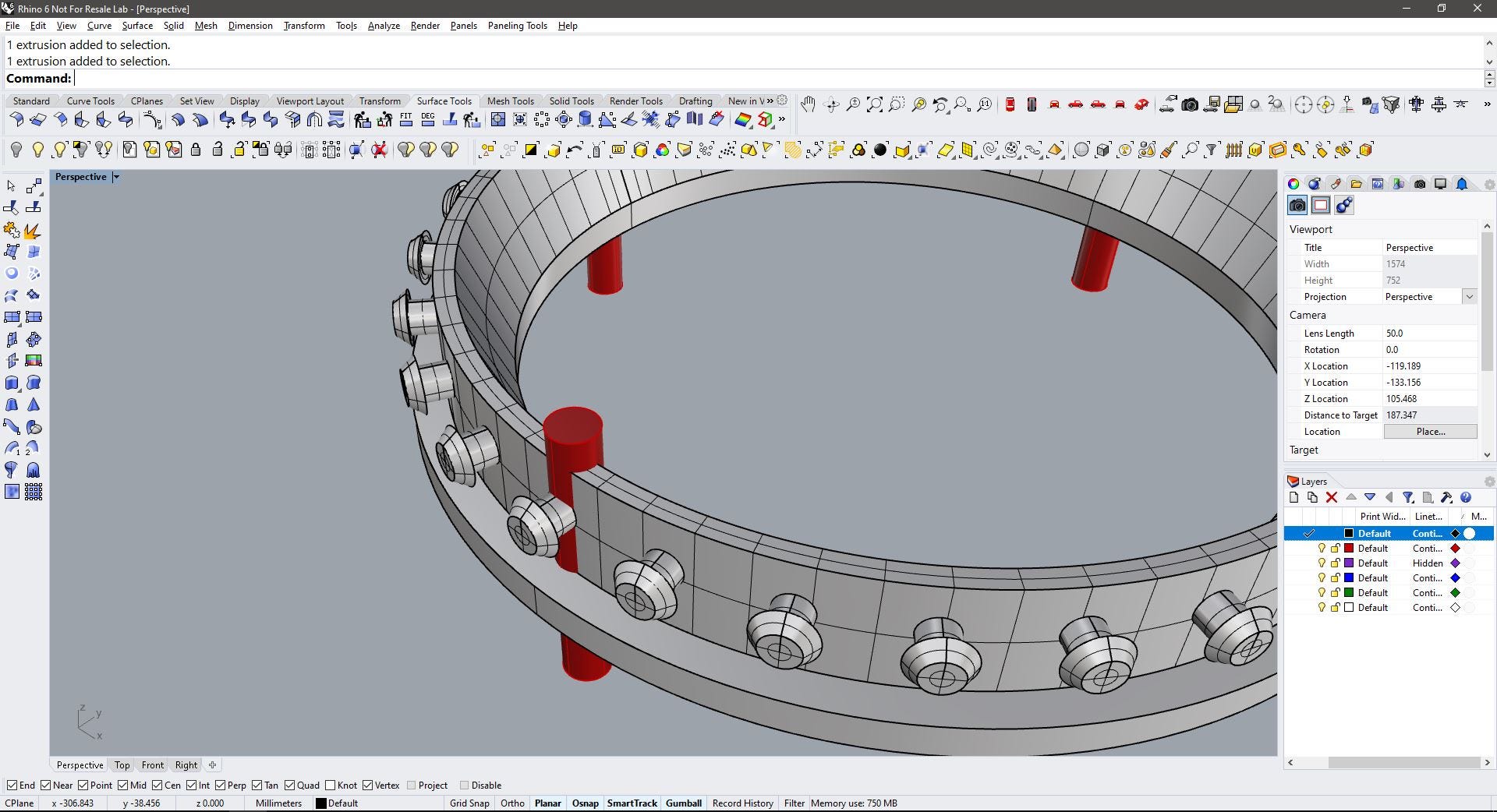
These are the final measurements for the central column, I added a fillet to the edges, the hole in the center, and the sketch for the base with 4 holes for the spax screws(the same that will be used for the rings).
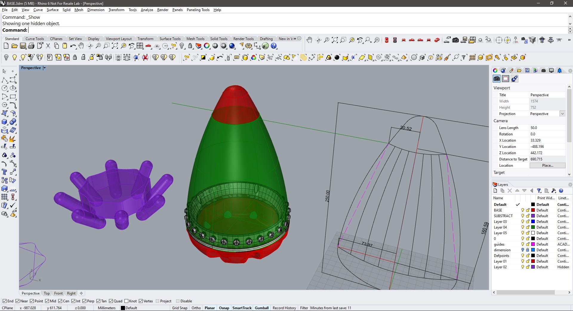
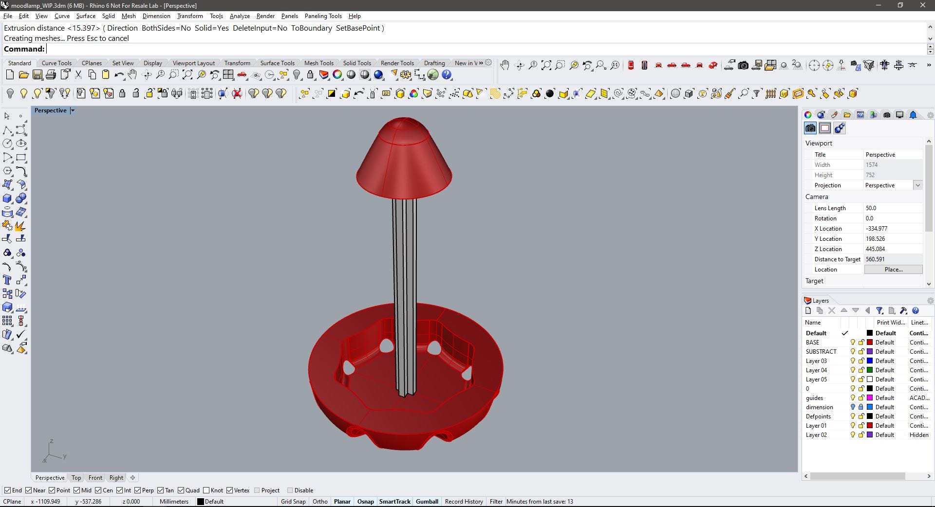
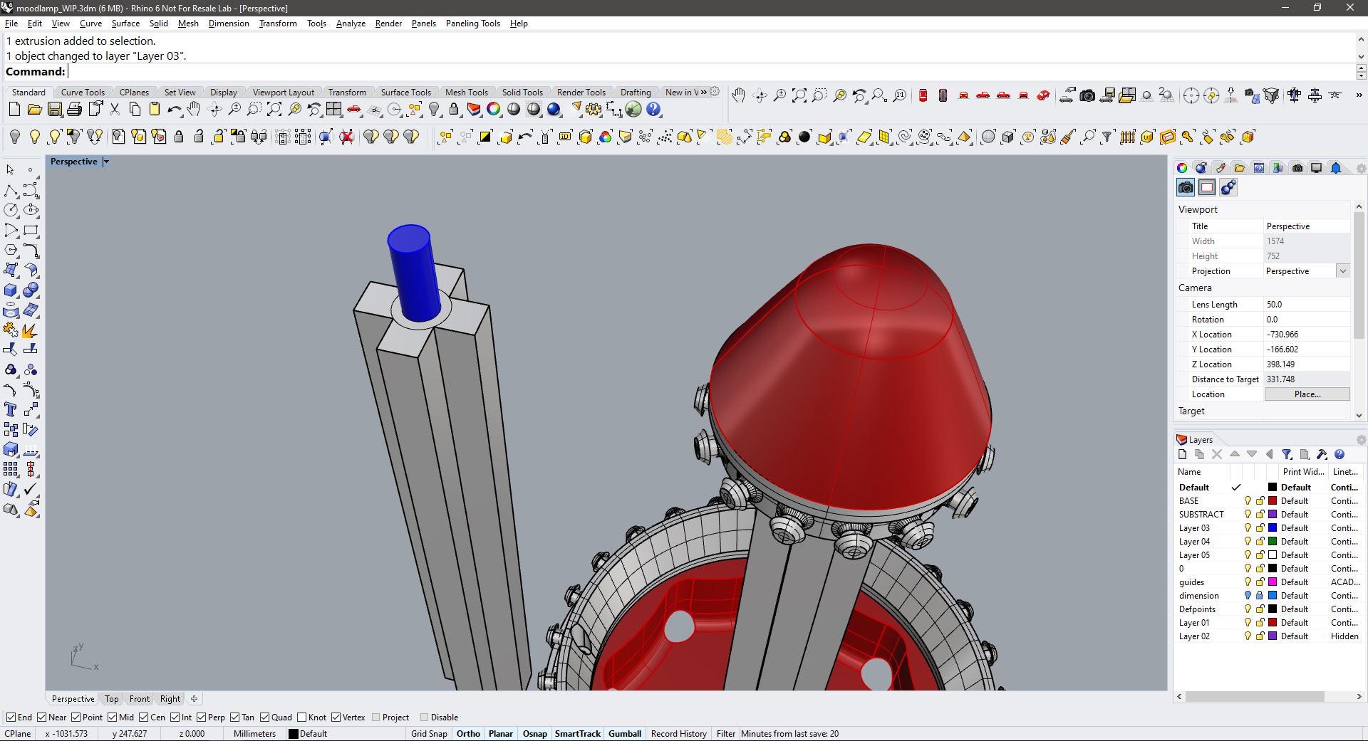
This shows the final shape of the column and the placement of the column and the rings. All these will be made by 3D printing.

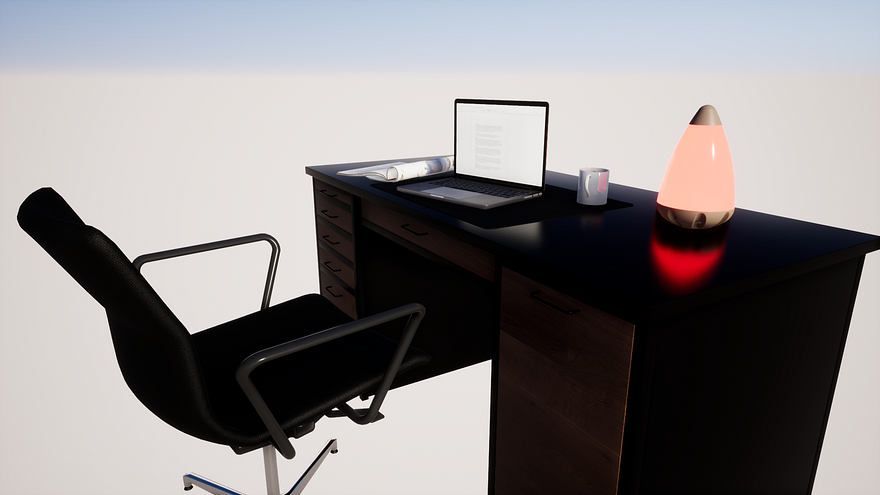
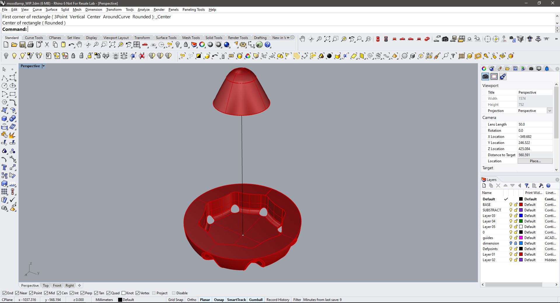
I decided to make a quick visual test with the pieces I had already modeled, so I arranged them on different layers and assign different materials. notice that I placed a mockup ballon inside the device, it’s hard to see because of the skin in green. Notice that also the Tip has 2 different materials because I’ve not decided yet if this would be made from wood or wood and resin with a LED.
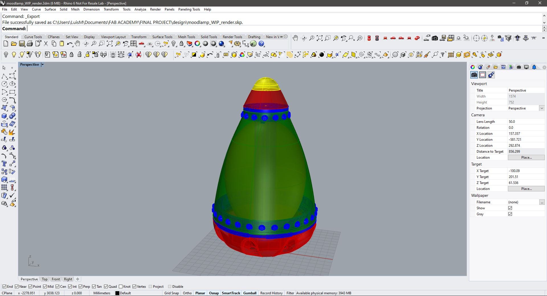
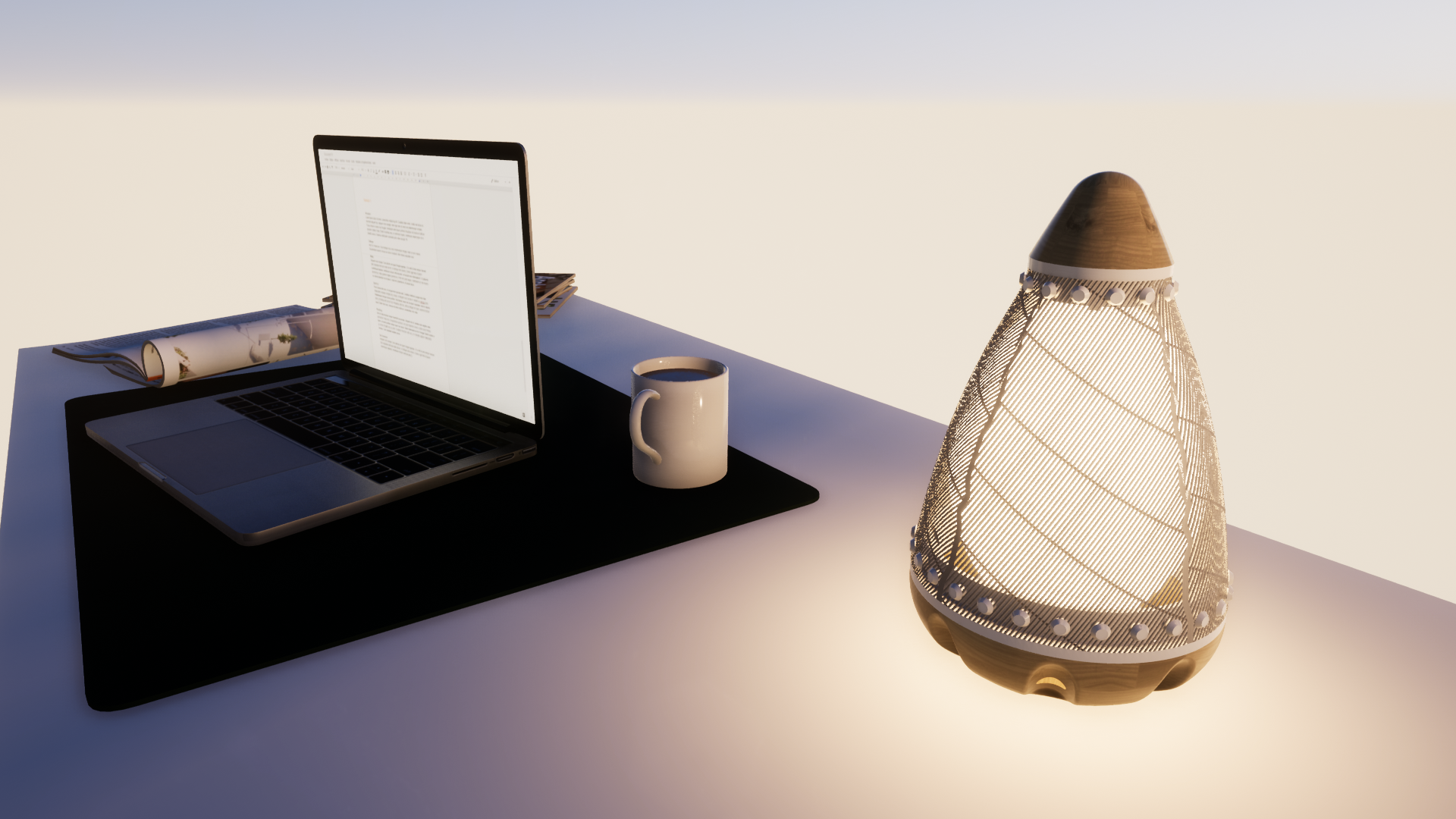
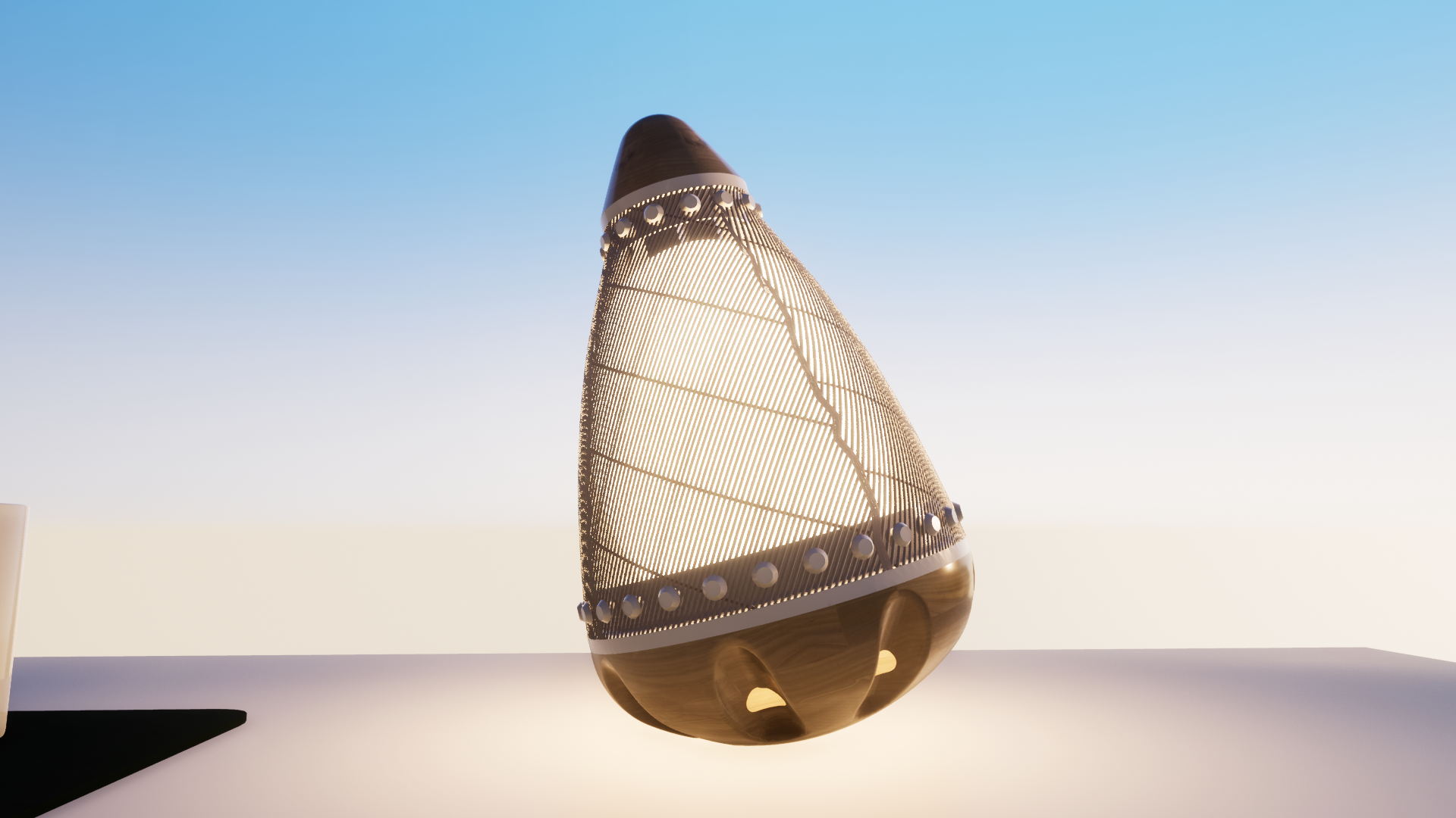
I exported the geometry from Rhino to Twinmotion render engine to make a quick visualization. In this stage, the flexible skin was simulated with a mesh-like material. Now we can see the ballon inside the device. The ballon will work as diffusor for the light (a Neopixel ring would be placed in the base).
How can a ballon fit inside if there’s a column in the way? you may ask. Well, I’ll be using a donut-shaped balloon. or maybe two of them stacked.
The pulsating action of the device will be made by applying pressure on the balloons, causing them to expand the sides of the flexible skin, thus making the device a tangible interface for respiration training.
Right after this test, I thought that maybe a central column it’s not the best option since it will overly fix the shape and that maybe the skin and the balloon (a regular one) would be enough to support the tip since it will fit with a slight pressure between the top ring and the compression mechanism on the base (to be designed).
Spoiler alert: Of course it will be enough! So long central column!
I starter working in a second pattern for the skin, this time a more structured design, I tough that a Voronoi pattern would fit lovely to the design, and its a very pleasant pattern.
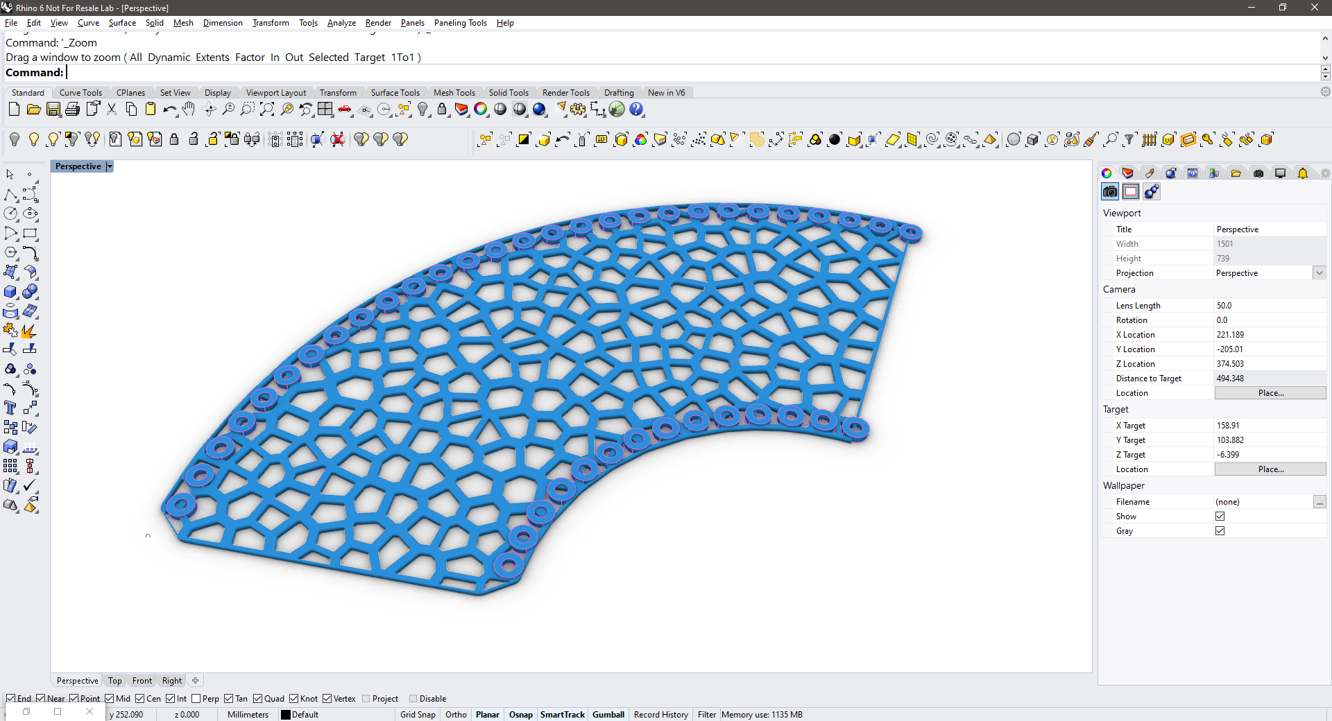
Back in the Rhino environment, I made a quick definition of the Voronoi skin using Grasshopper. I made this pattern right onto the cone-shaped solid (previously seen in green) and this is the result:
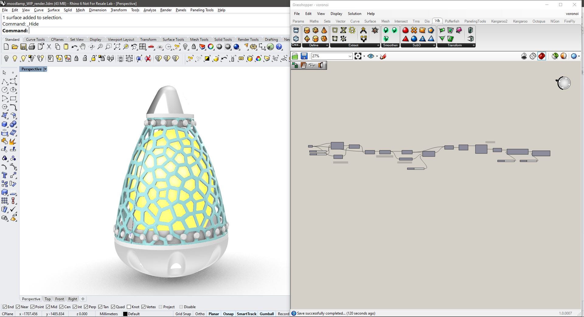
The Voronoi pattern looks very cool as skin, and thanks to the Grasshopper definition because it is parametric, it could be easily modified if additional testing is required.
As I would need to apply the same pattern on the flattened surface of the skin, I would simply change the target geometry in the grasshopper file.
Production:lets make!
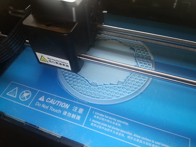
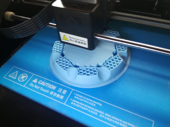
3D printing the base
As I was happy with the pear shape I decided to print the base. The development of the shape it's also in Computer-aided Design week and the printing process in 3D Scanning and printing week.
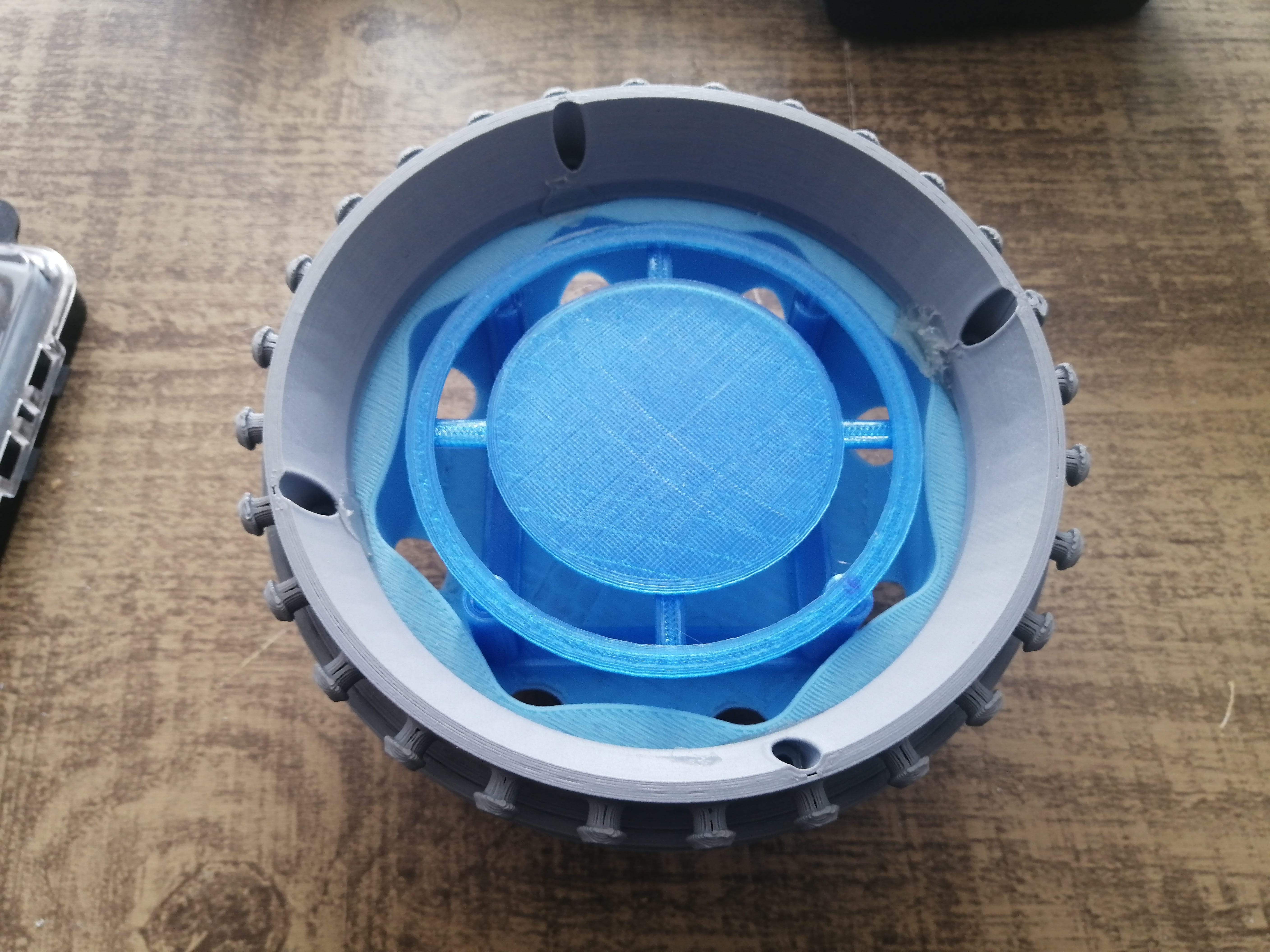
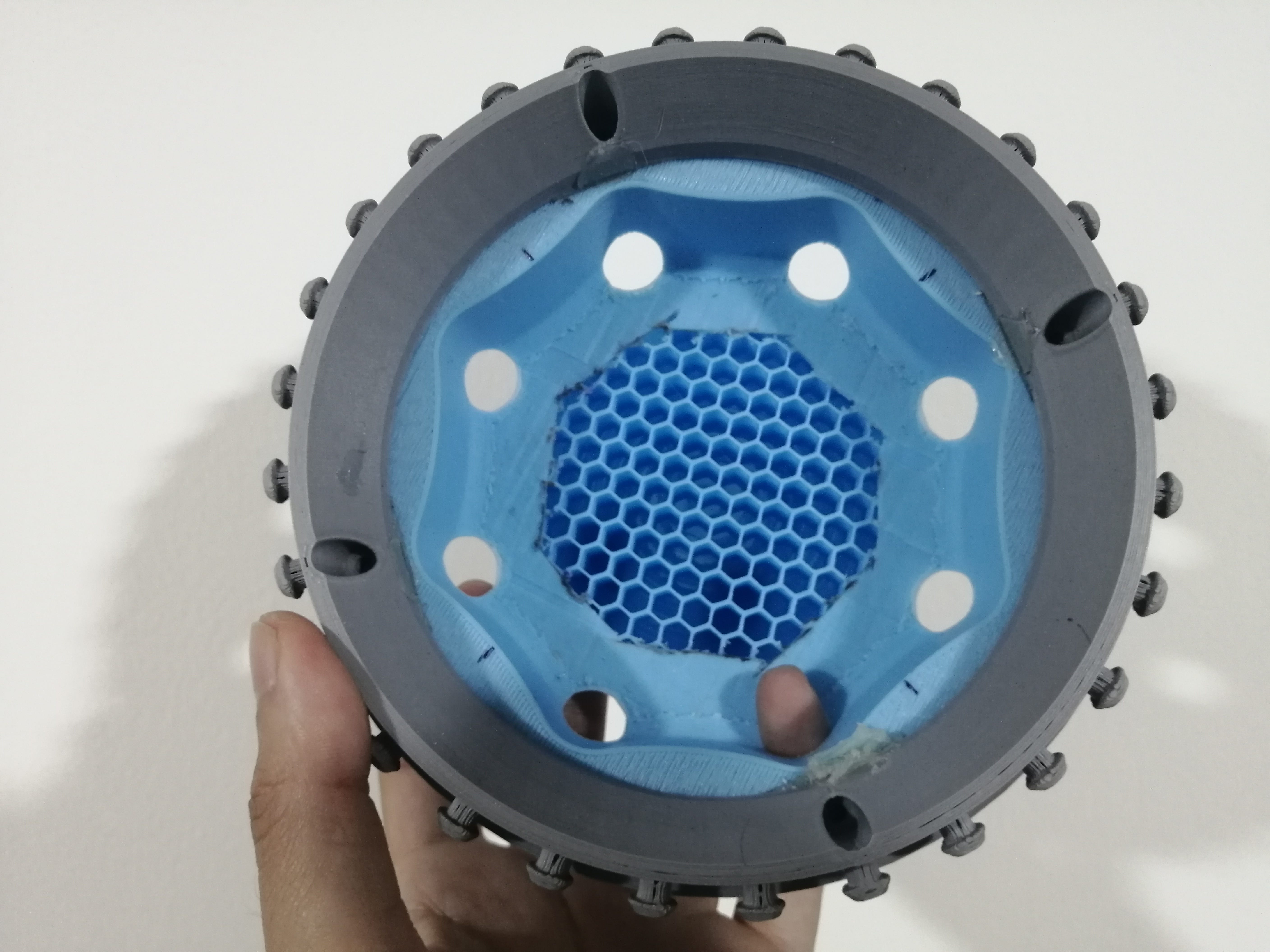
The base should be heavy enough to balance the lamp and it should work as housing for the electronics components. This shape has a hole in the center for the components and holes around for ventilation and for the heart rate sensor.
The final base shape prototype, now I need to design the junction between the base and the body of the lamp and the structure that will support the top. (maybe a central column?)
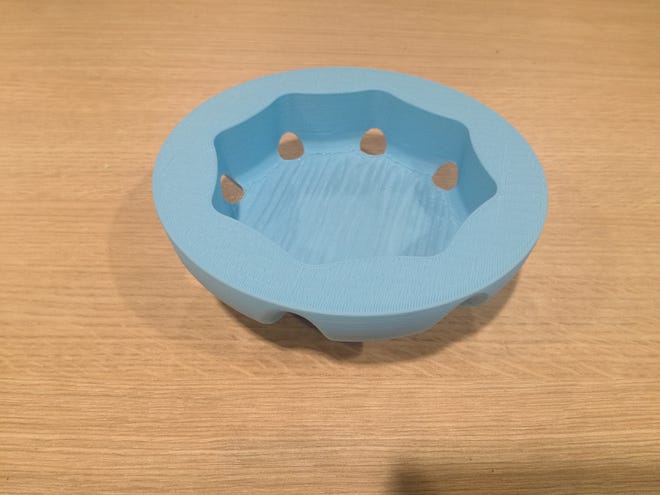
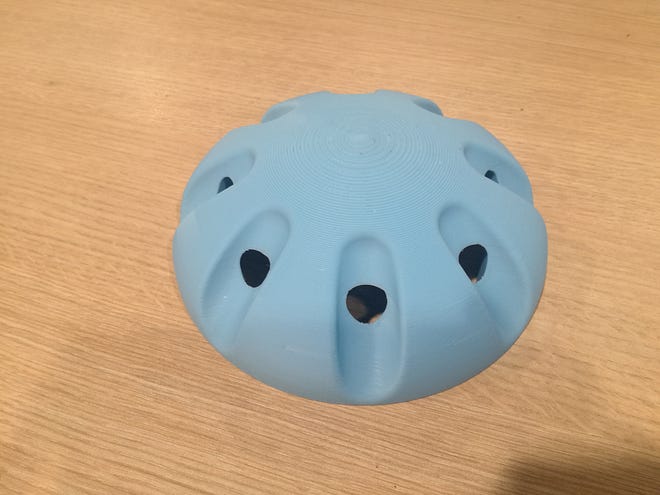
While of 3D printing the base I can later use this shape to mold and cast the base in a heavier material. Anyway, the swinging of the base has a very satisfying movement due to the layers of the print.
The 3D-printed base can later be used to mold and cast the base in a heavier material. Anyway, the swinging has a very satisfying movement due to the layers of the print.
3D printing the rings and tip
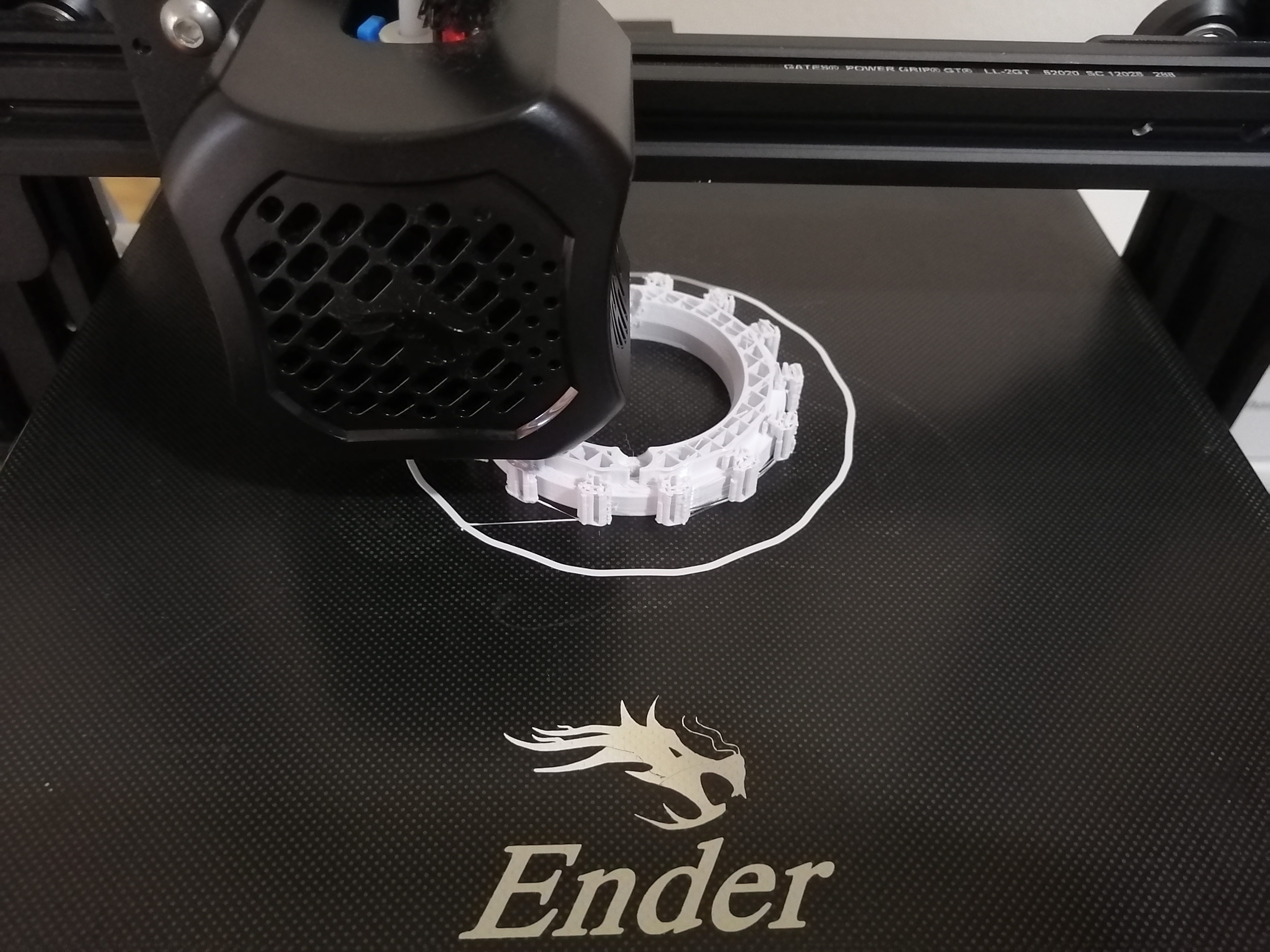
The base and top ring printing went uneventful, I used my newly acquired 3D printer, to experiment at home. The settings for both rings are the same.
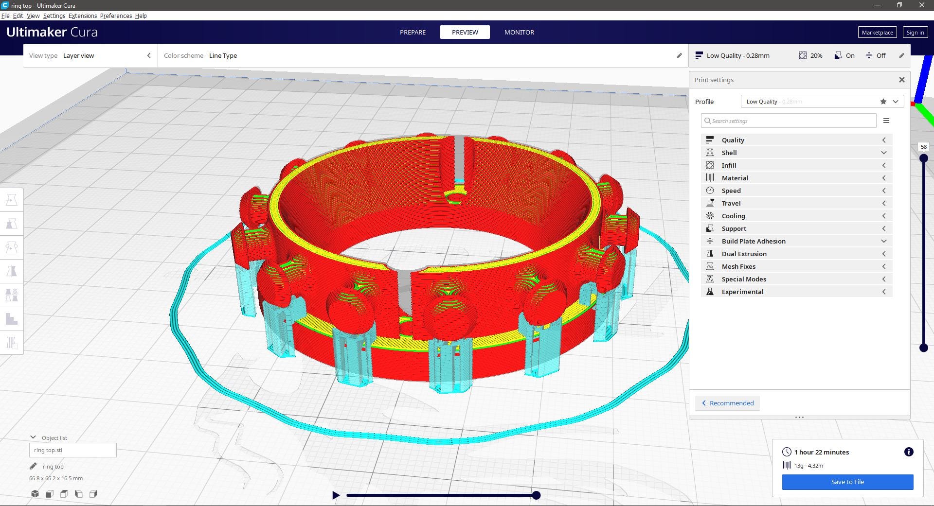
I chose a “Low quality” setting for the prints to make them faster. This caused minor flaws, especially on the base and top of the buttons. Some tunning needs to be made for the supports, but overall the printing quality was good.
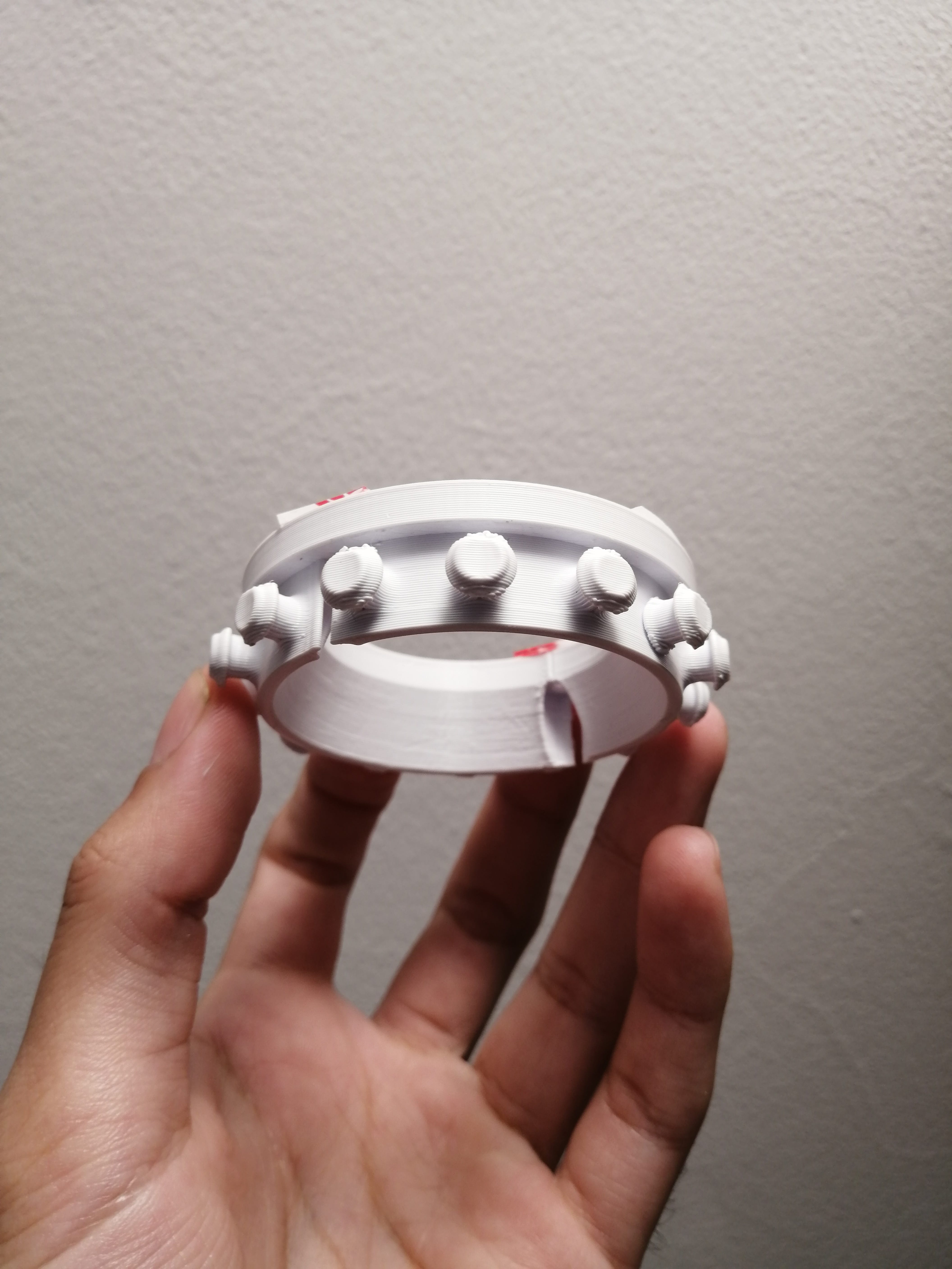
This is the final result for the top ring, with some blobs on the rounded parts.
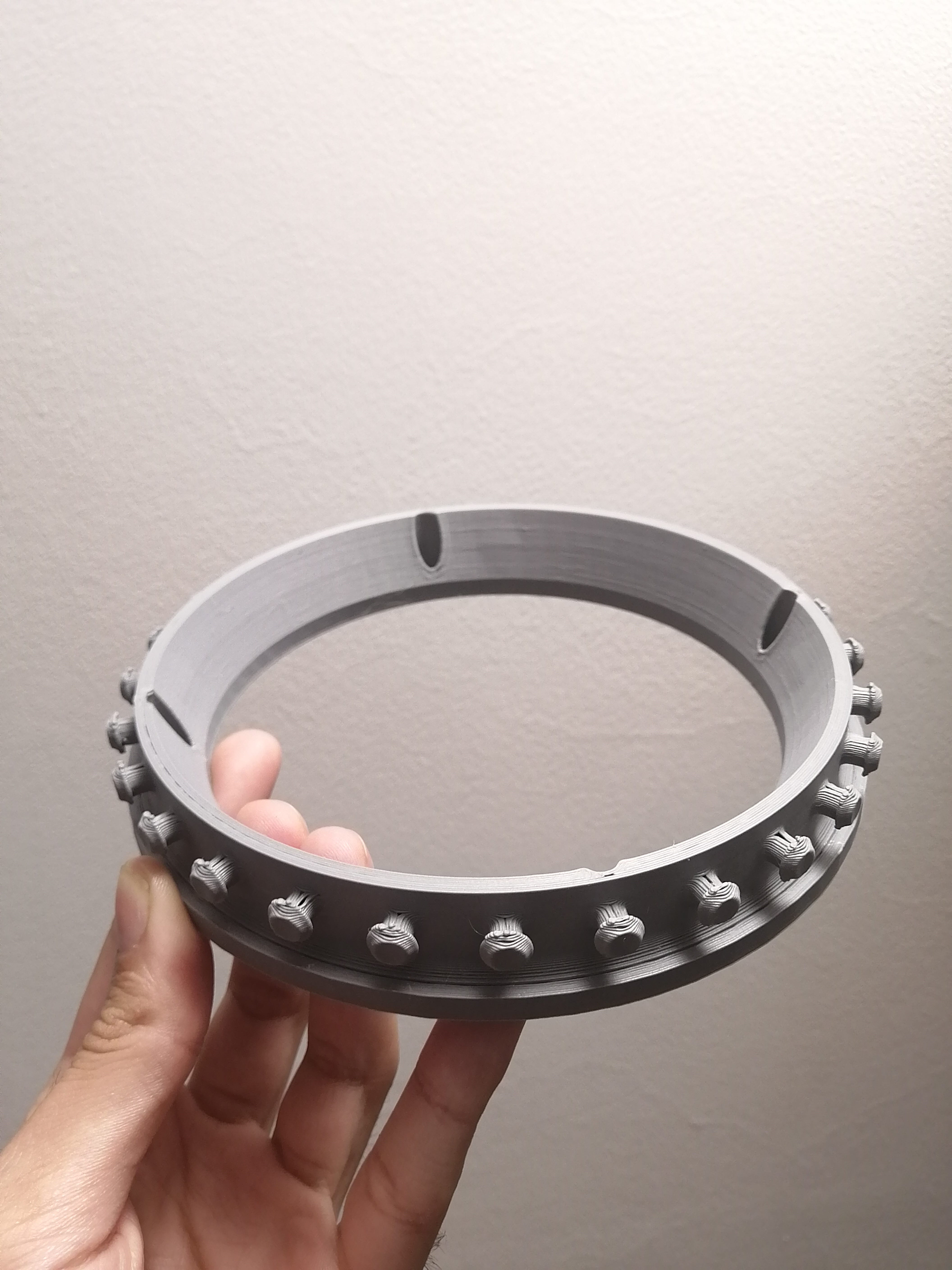
This is the final result for the bottom ring. This was made using a different type of PLA called Polyterra Fossil grey color. Notice 4 holes to attach the ring to the base using screws, in case the base is made from wood for the final design.
The tip is made from the same PLA and here is shown assembled with the top ring, the top ring also has holes for fixing screws, but in this setup, the tip and ring are bonded together with double-sided tape.
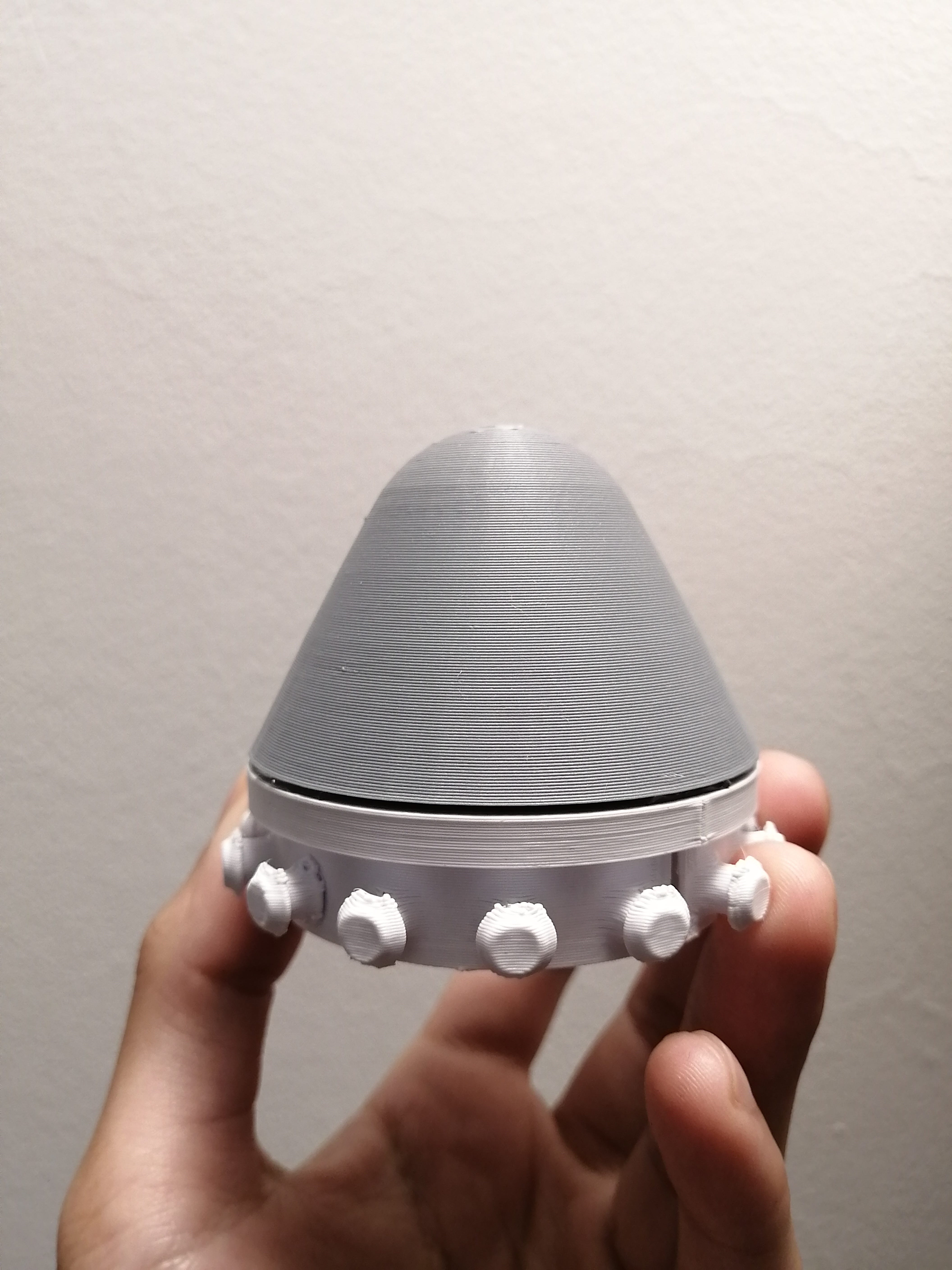
The same bonding technique is applied to the bottom ring and the base.
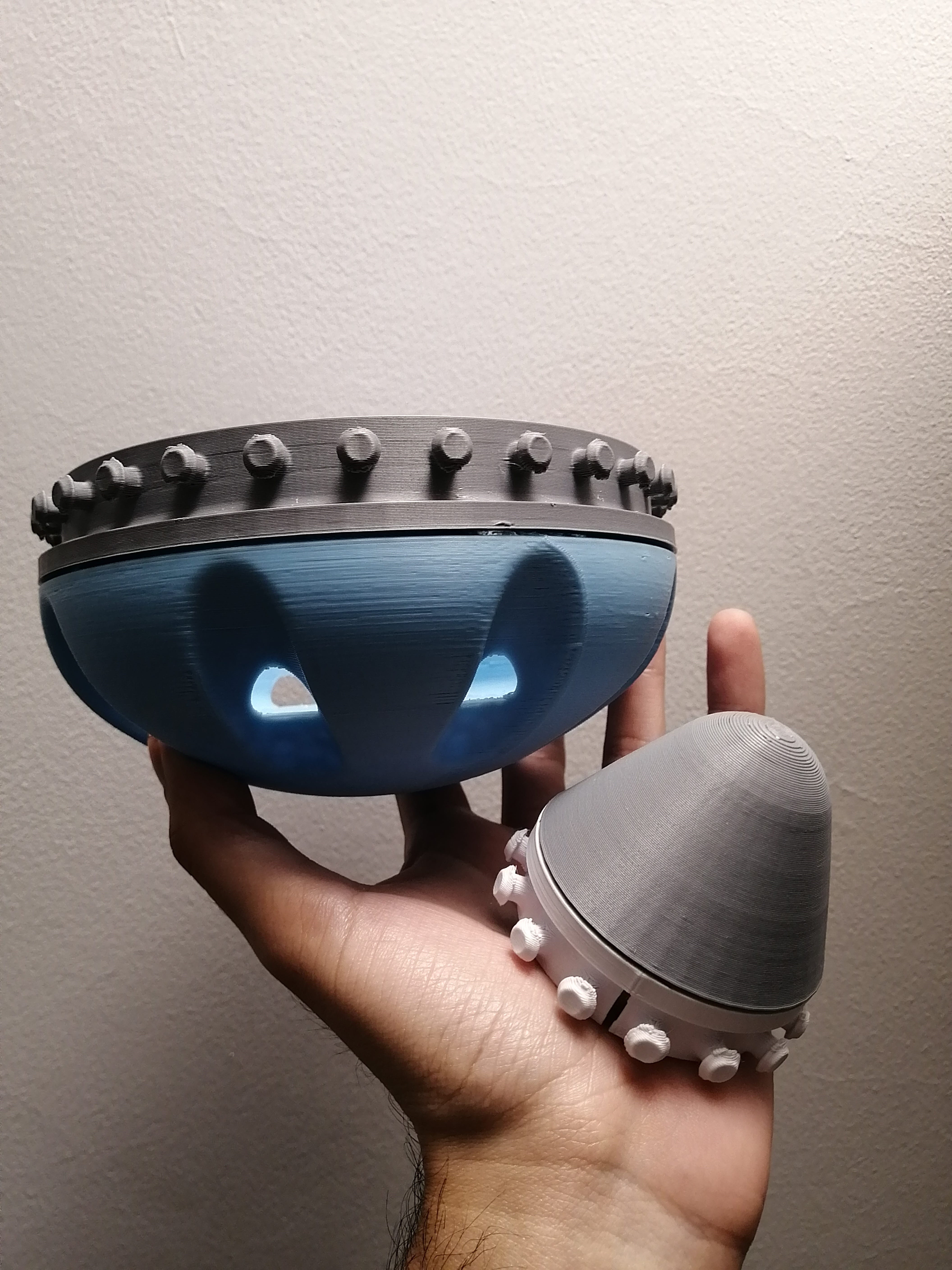
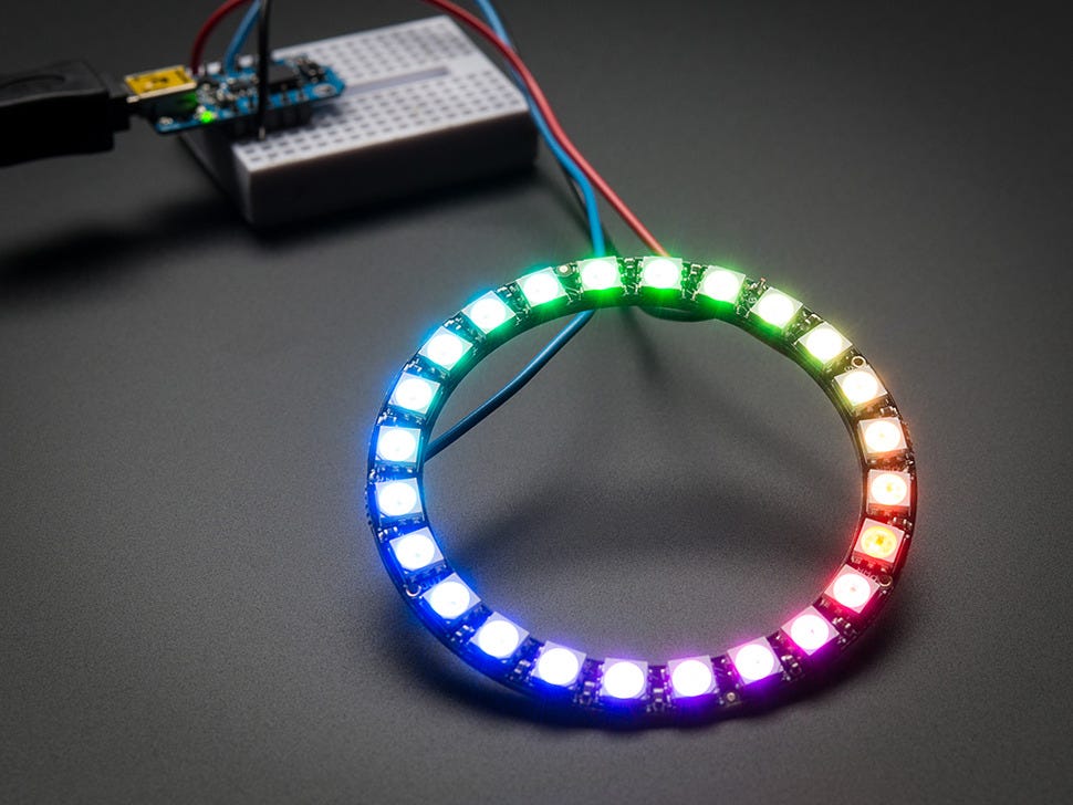
I was still missing the center part of the design, but as it was planned this would be some kind of inflated diffuser, I made the first test with a white balloon and attached a LED strip to the base to get a better idea of the light.
Some of the dots are noticeable from the outside, so a better placement for the lights should be on the base and not on the inner circumference of the ring.
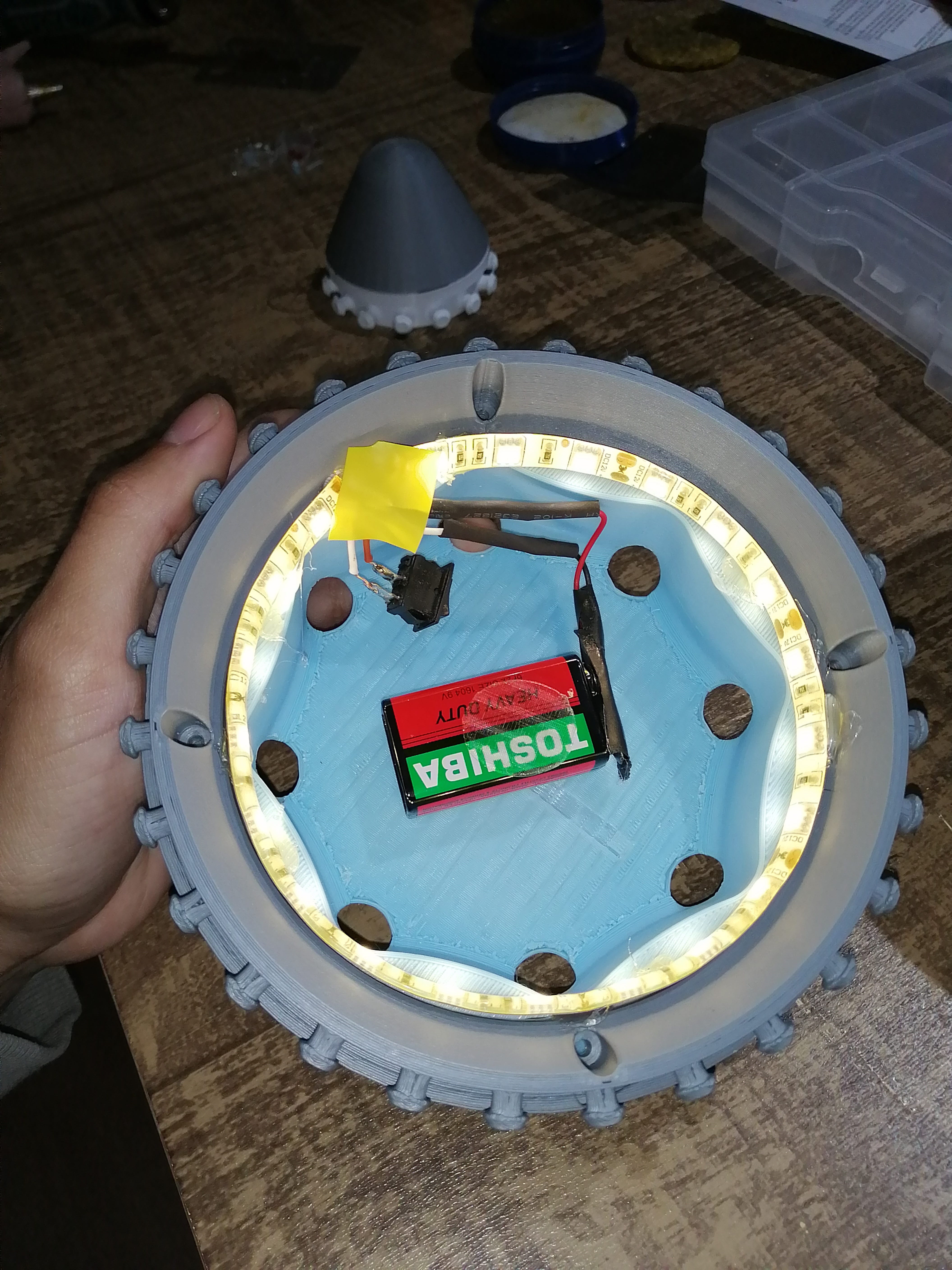
I plan on using an RGB Neopixel ring instead of an LED strip on the base to show the reading taken by the pulse sensor and reflect different stimuli by color code. More of this programming is in the embedded programming assignment.
Molding and casting the skin
To hold the printing parts together and have the ballon diffuser contained I need to make the skin. This would be soft and stretchy at the touch, so molding silicone would be a perfect choice. Although I would use a different technique than the one shown in the molding and casting assignment.
I modeled the skin flat using the same definition shown in the design section of this page, then placed small circles for the top and bottom rings to attach. But to be able to print this skin I need to cut the model into two parts to fit the printer.
This was still too big so I had to modify the printer settings to fit the building plate.
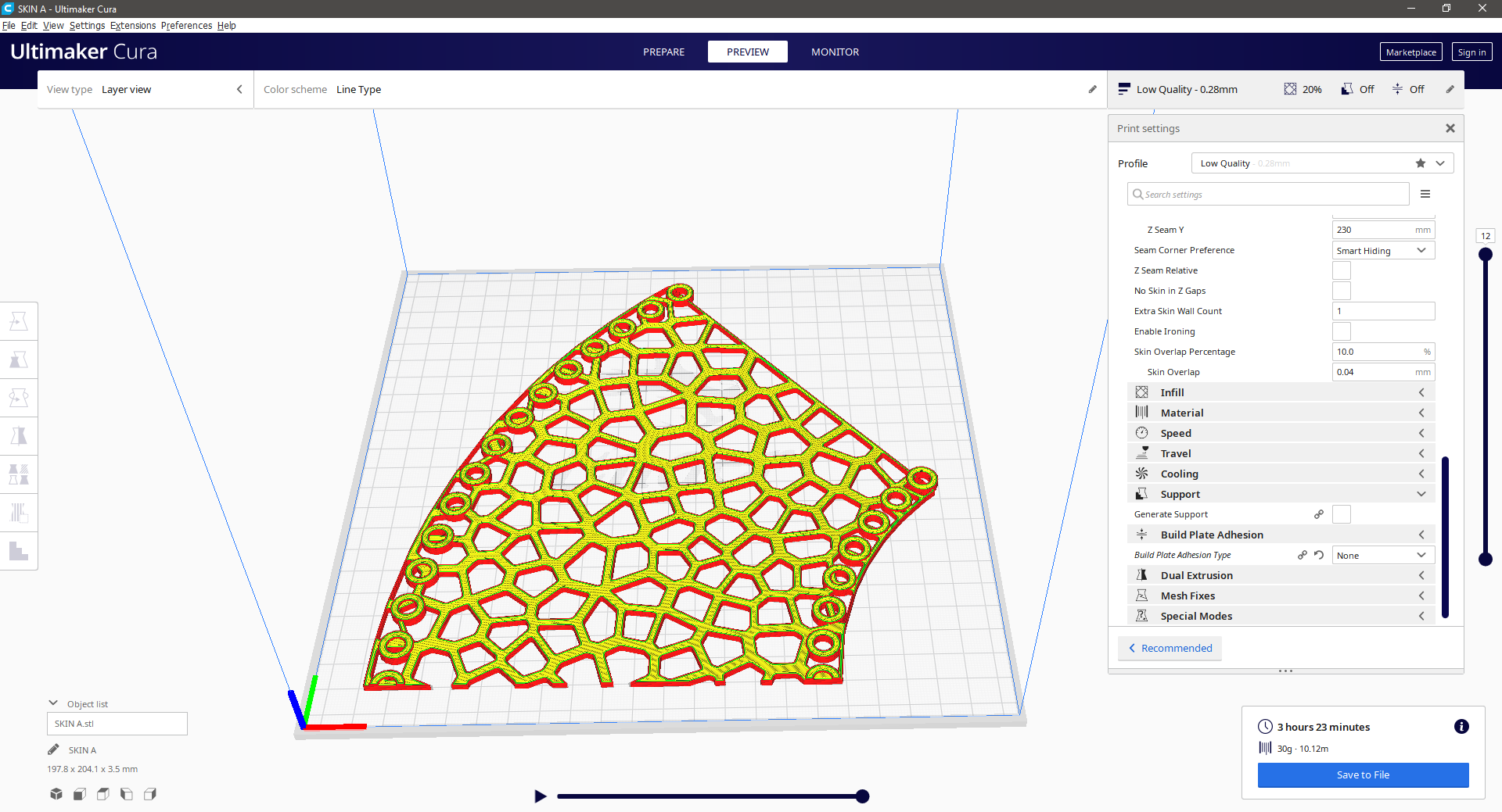
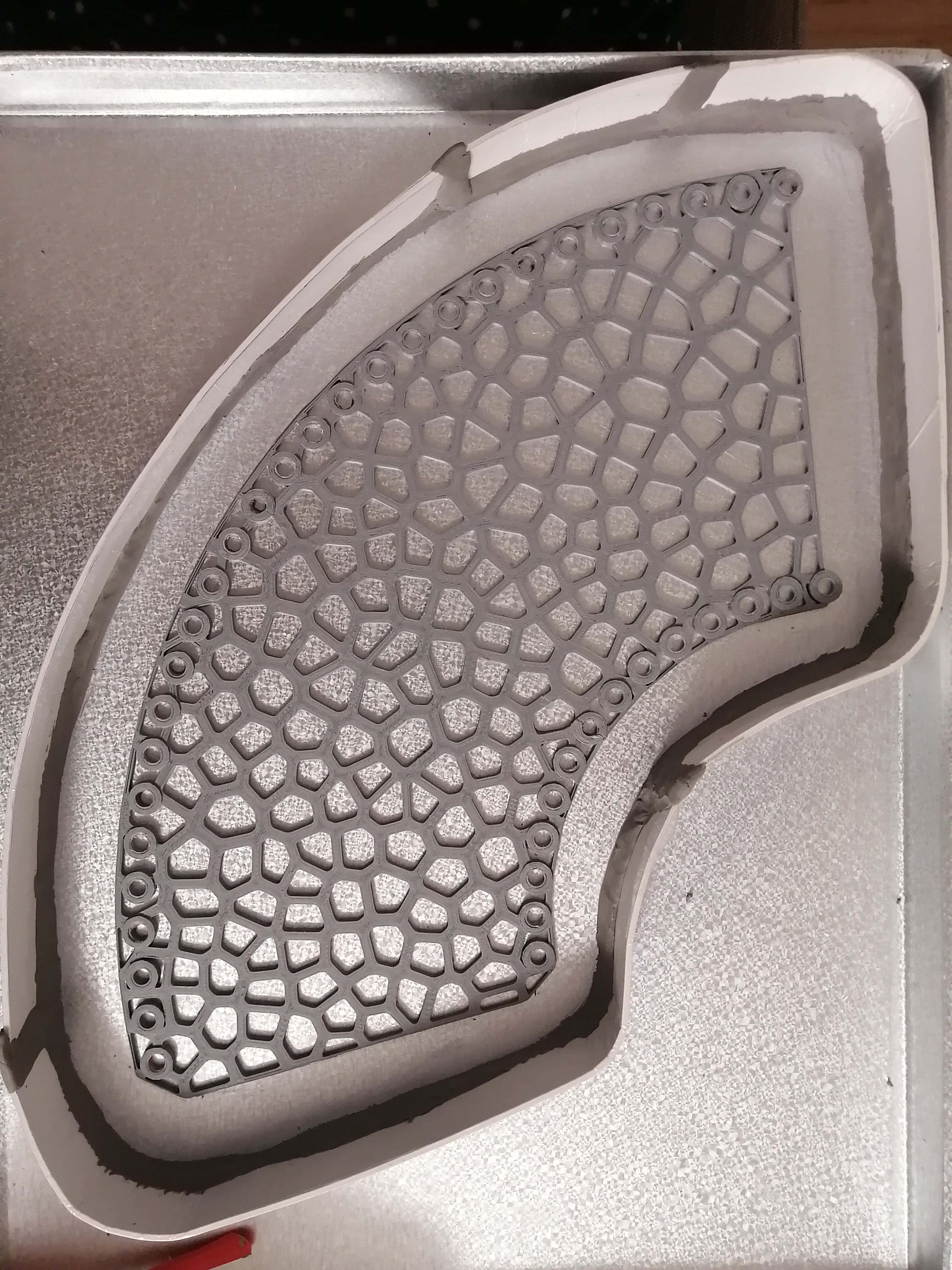
These two printed skin parts would be attached and fixed to a surface to get a silicone mold, but some processing was needed to clean the holes in the circles first with a drill, I know that this would have been made in software by boolean command but my PC kept crashing when I attempt the operation.
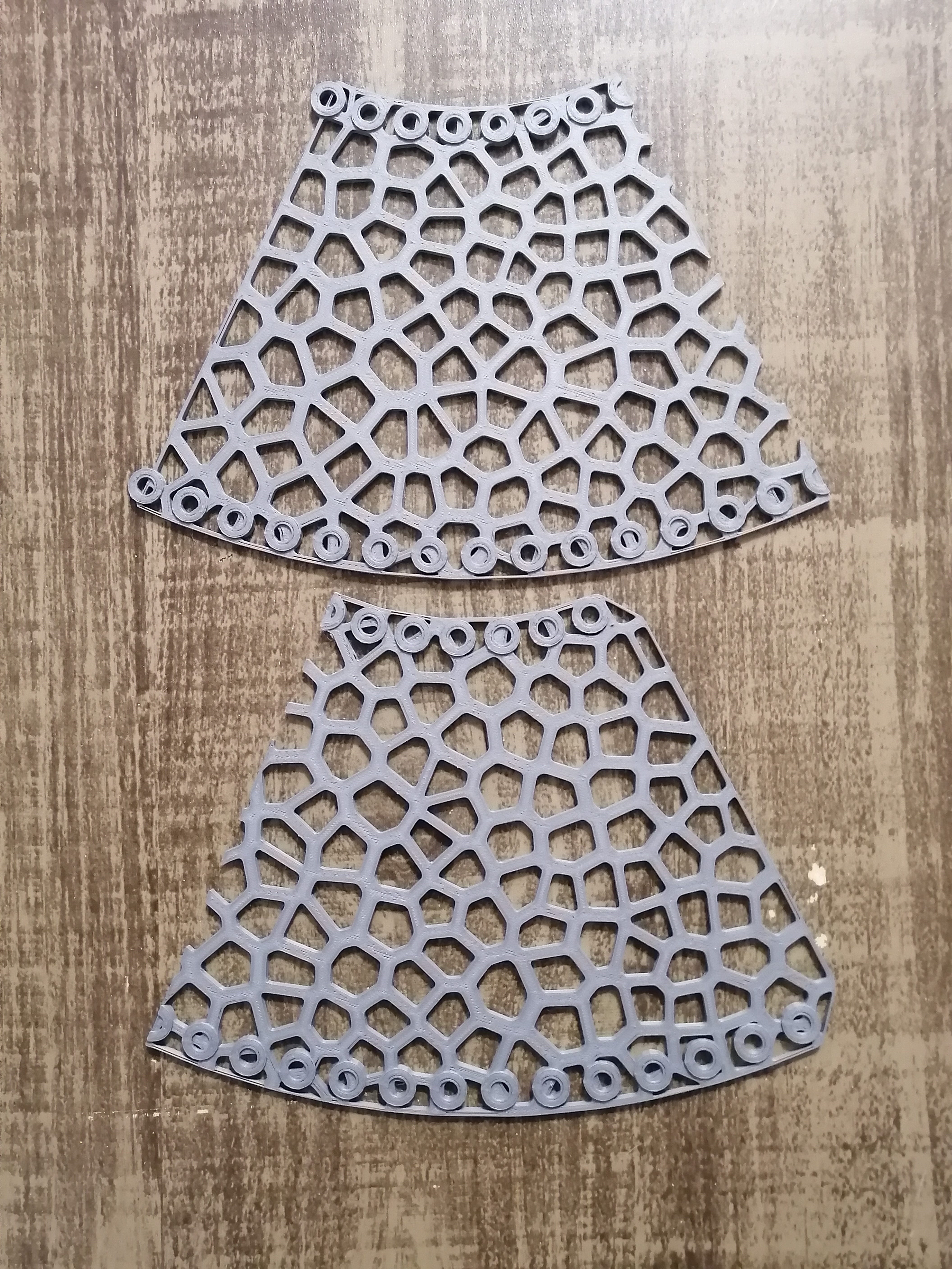
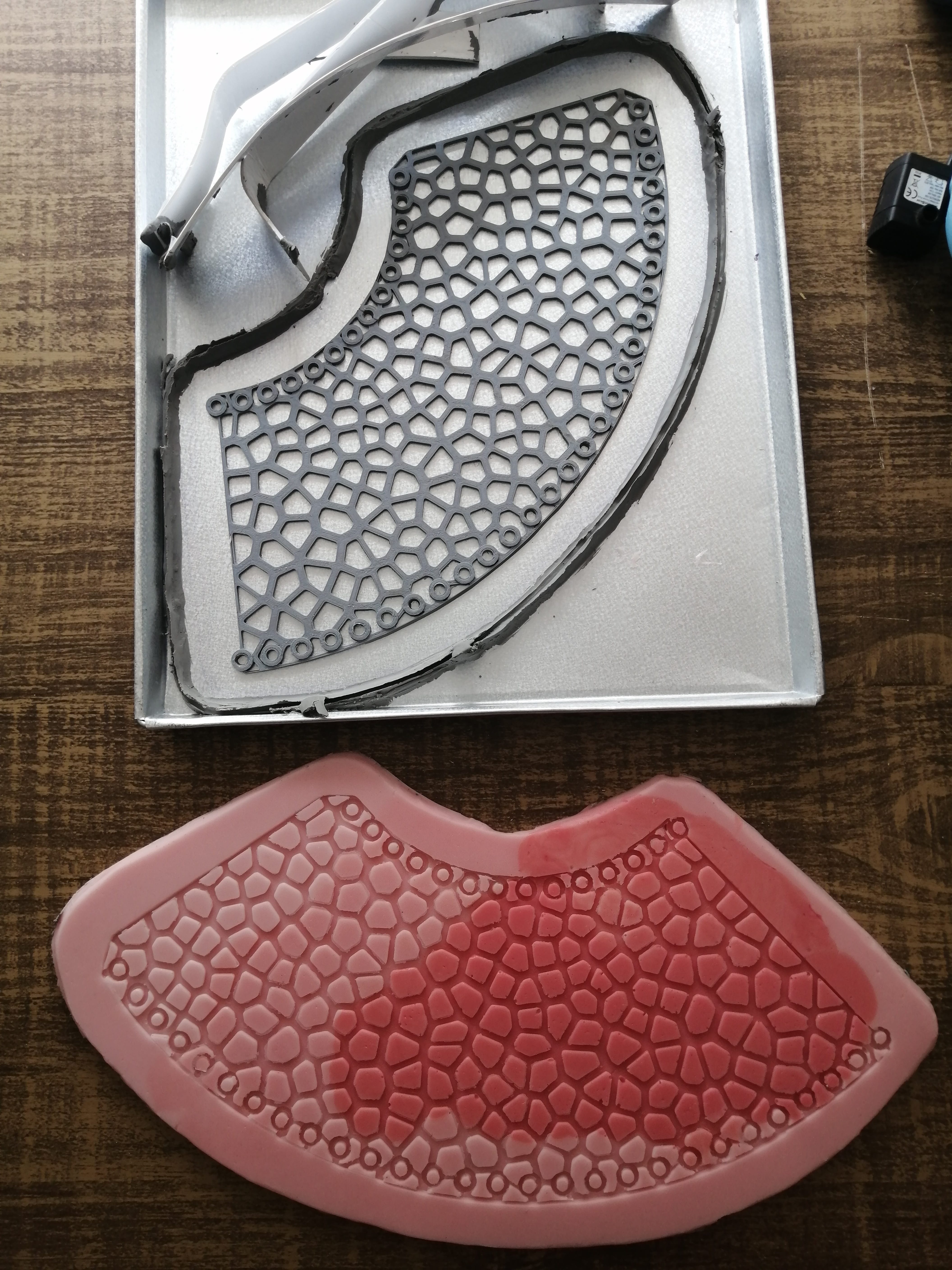
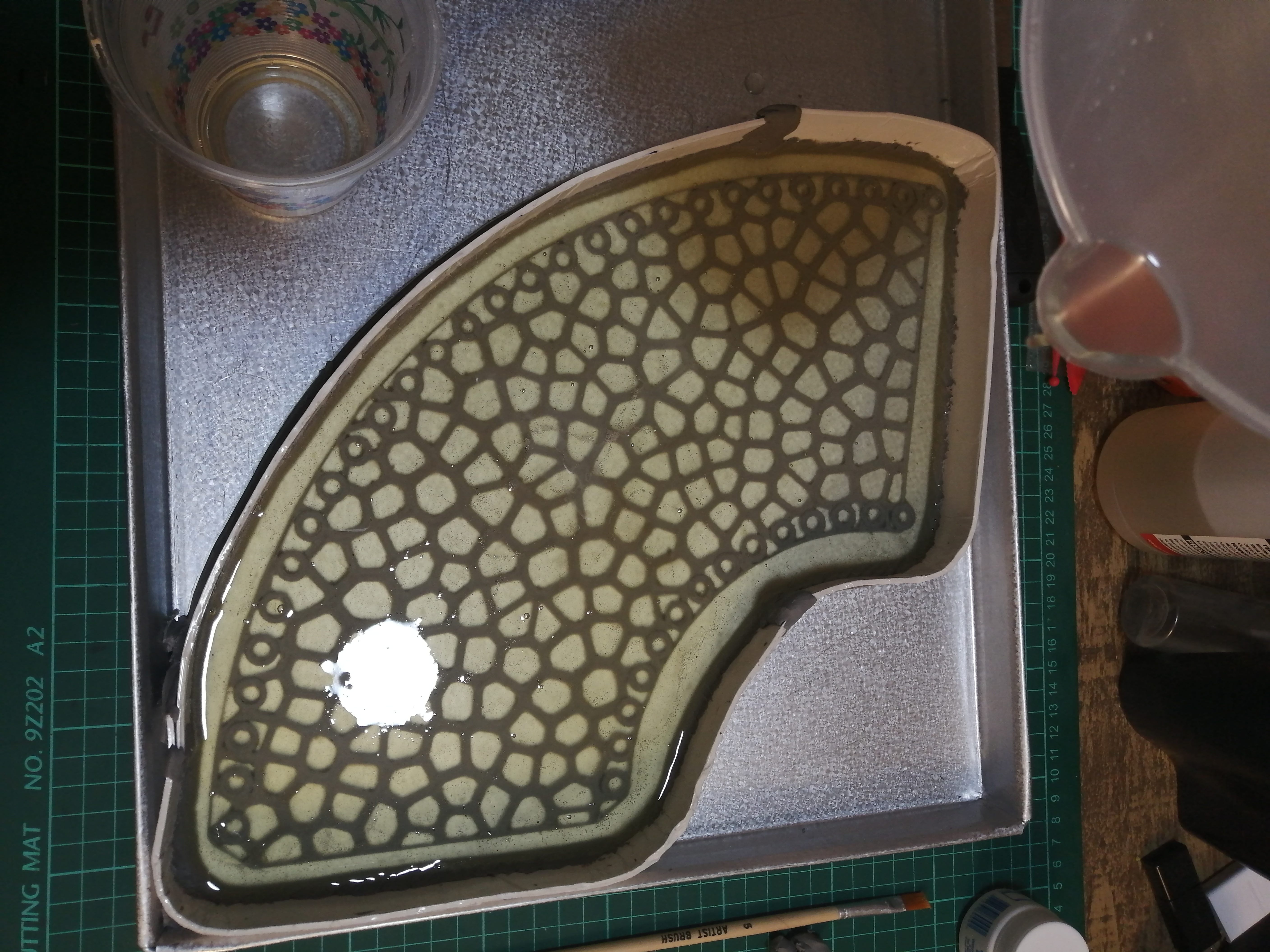
Here’s the part ready for the mold I poured silicone to get the negative and then I tried to do a silicone on a silicone piece.
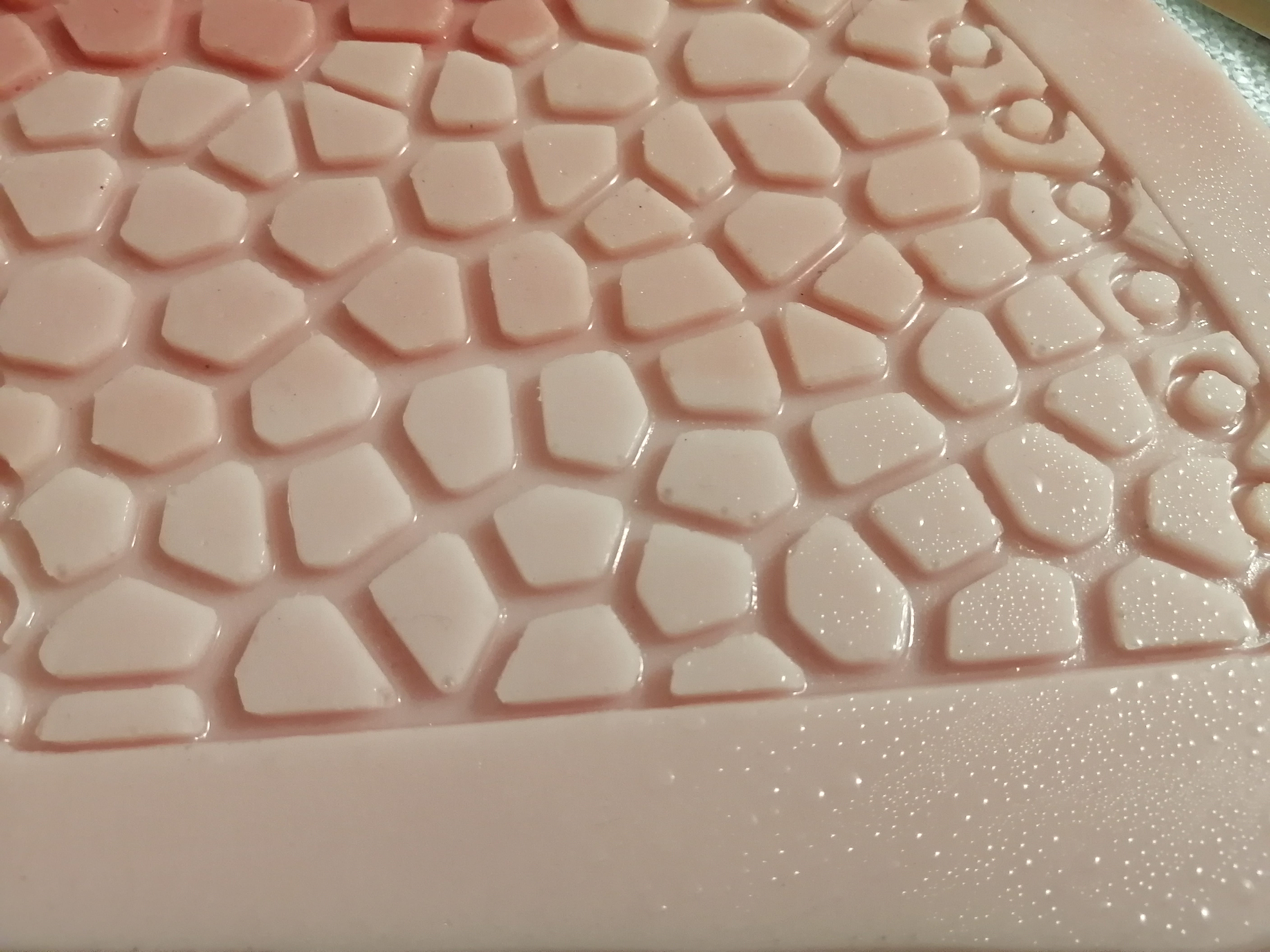
The mold was a success, with some minor bubbles here and there but overall a good result. I chose a flesh-like color to contrast with the green color of the skin to see better if there are some missing spots to be filled.
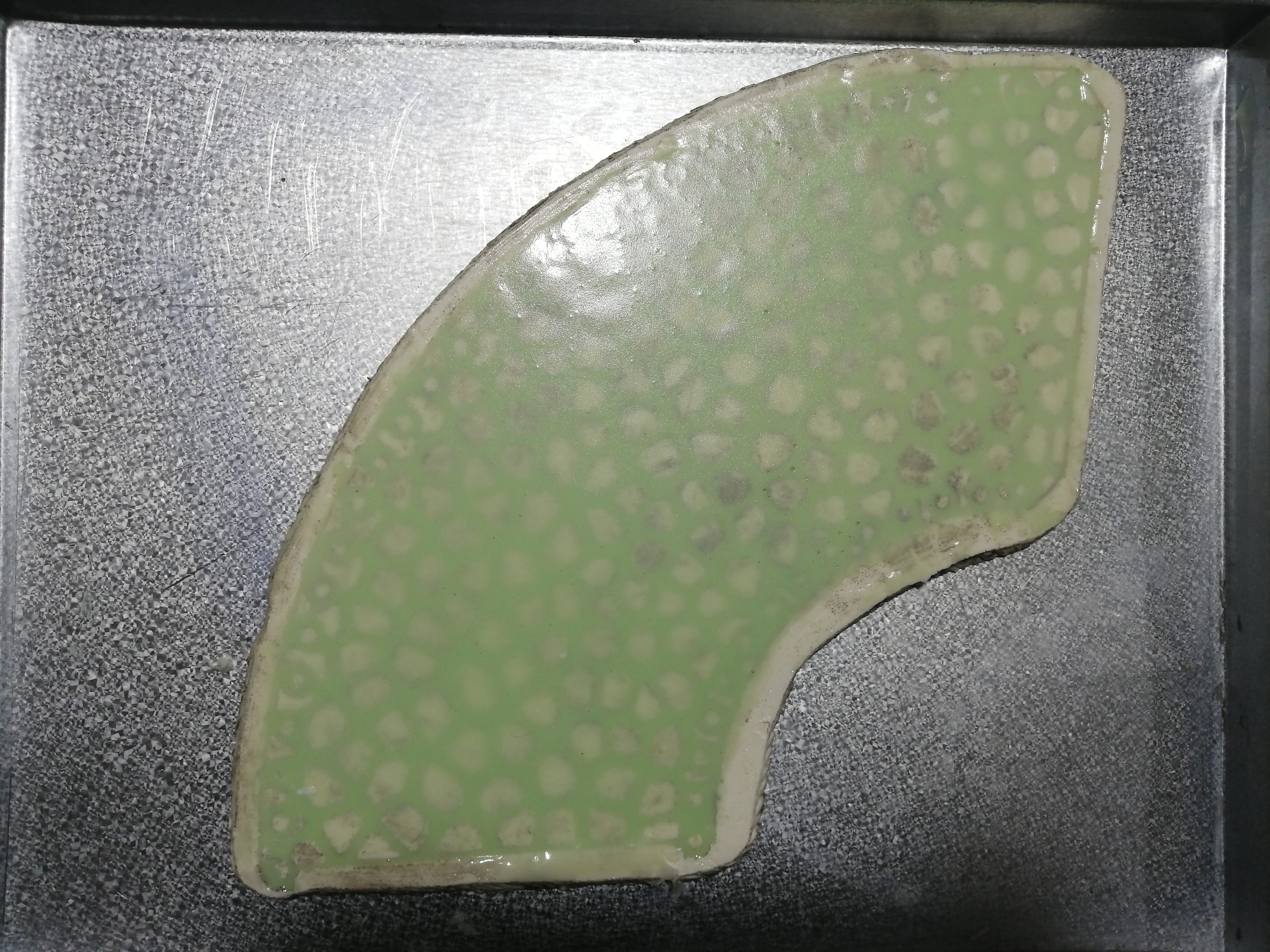
I made a couple of tests to prevent the silicone part to stick to the silicone mold, I couldn't buy a specific silicone-on-silicone demolding agent but the test I made with vaseline worked fine on small scale. So I’ve prepared the mold brushing a good amount of liquid vaseline
Next, I poured the green silicone (the final skin) and waited a couple of hours to release the part…
But the release agent did not work, so I ended up having a useless chunk of silicone. A lot of material and time wasted. Next time I would use specific products.
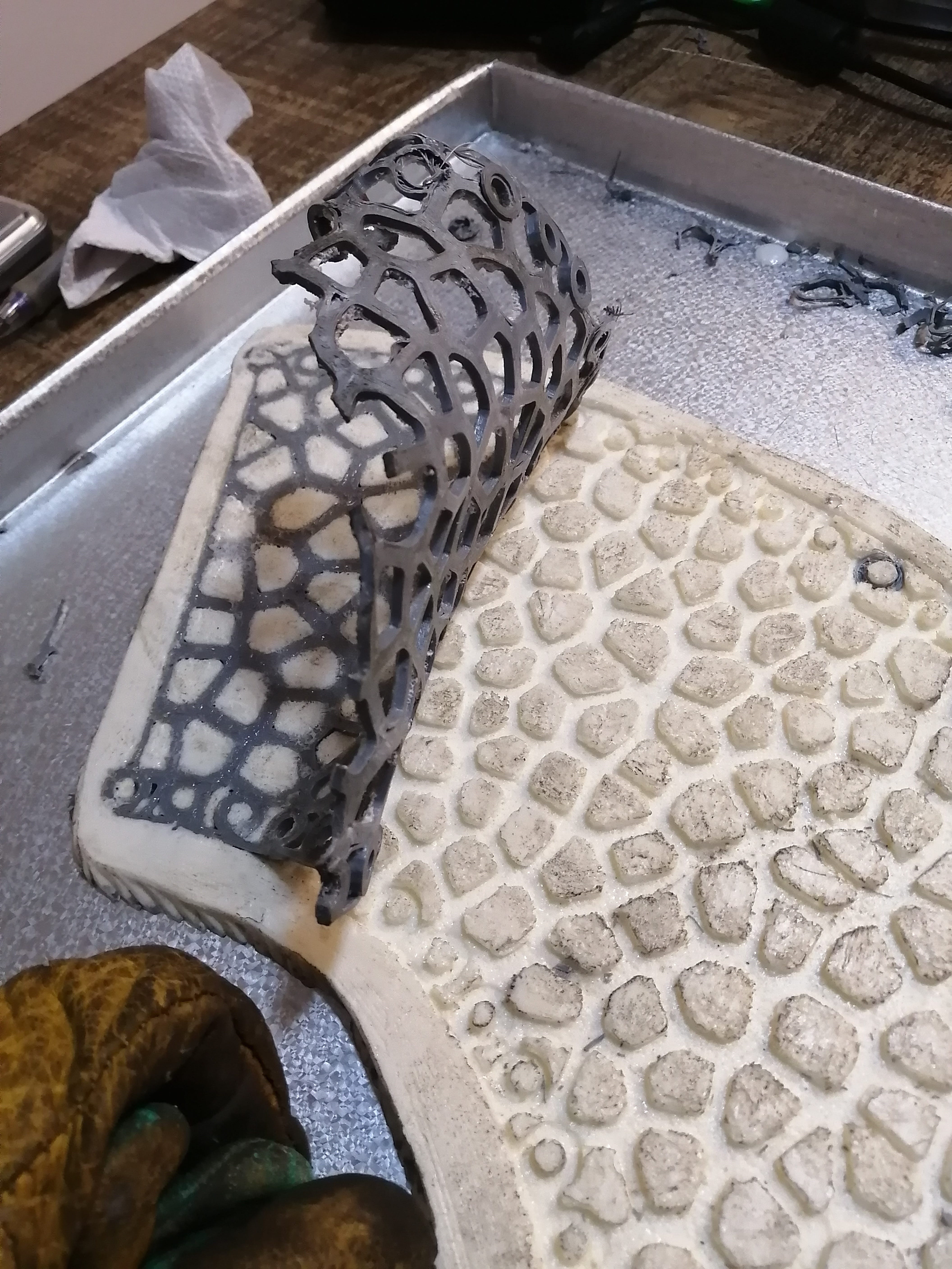
As time was running and I was also very short on silicone I made a risky experiment. I used a casting material (polyurethane resin) as mold and silicone as casting. This would probably mess up my printed parts.
As I expected the PLA was almost fixed to the resin, using a hot air gun I detached the PLA. The mold was not as good this time, the resin made a lot of bubbles, so this would reflect on the finished part.
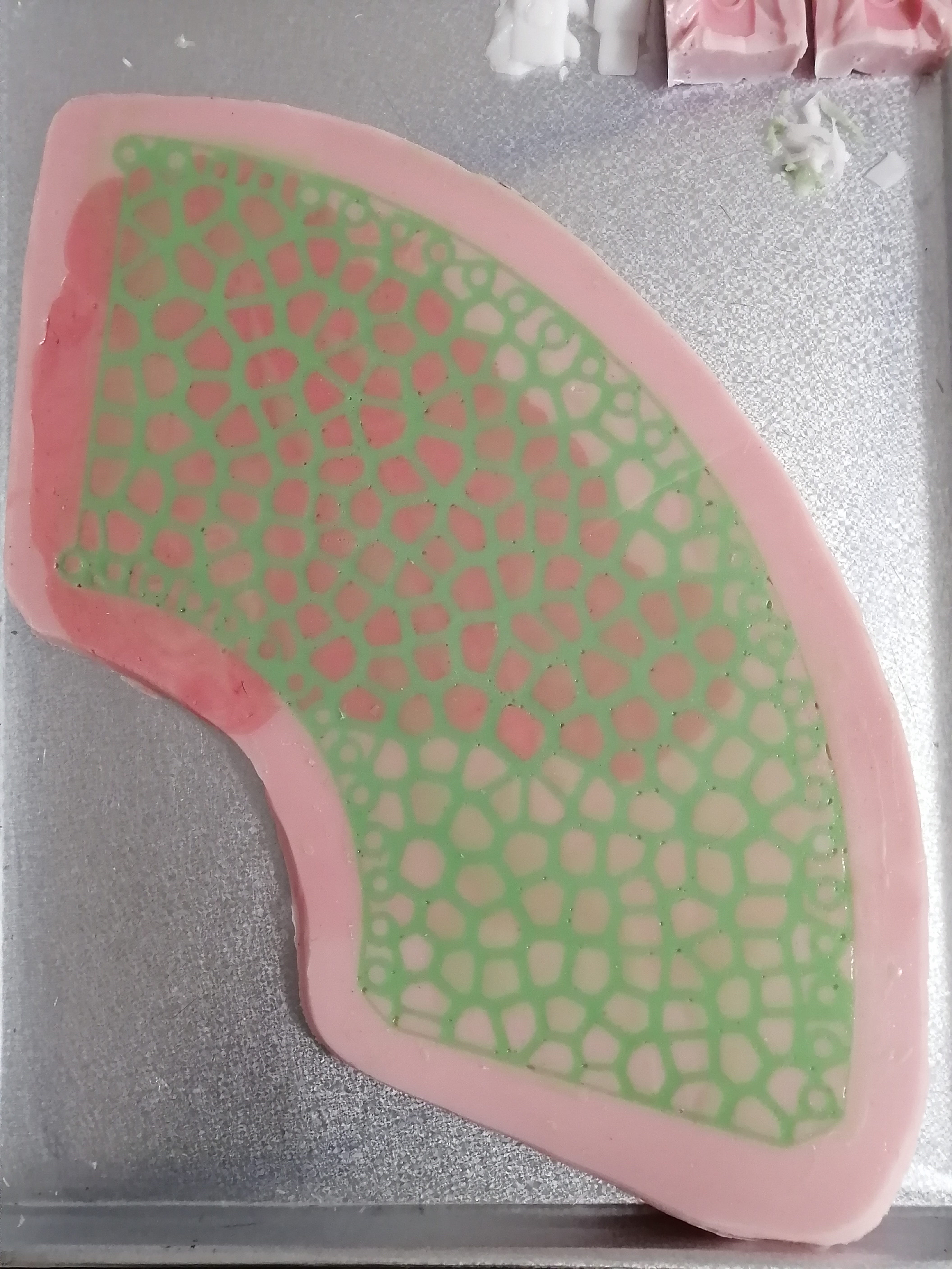
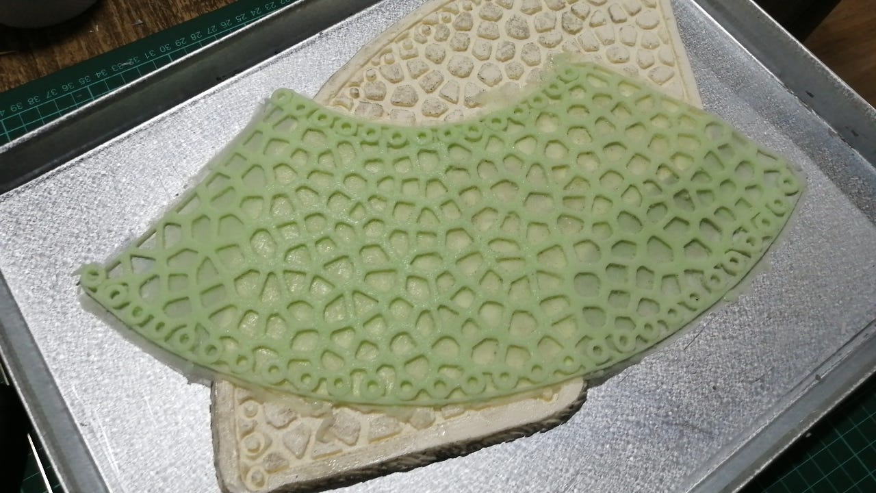
I repeated the silicone pouring of the skin, this time using the resin as mold.
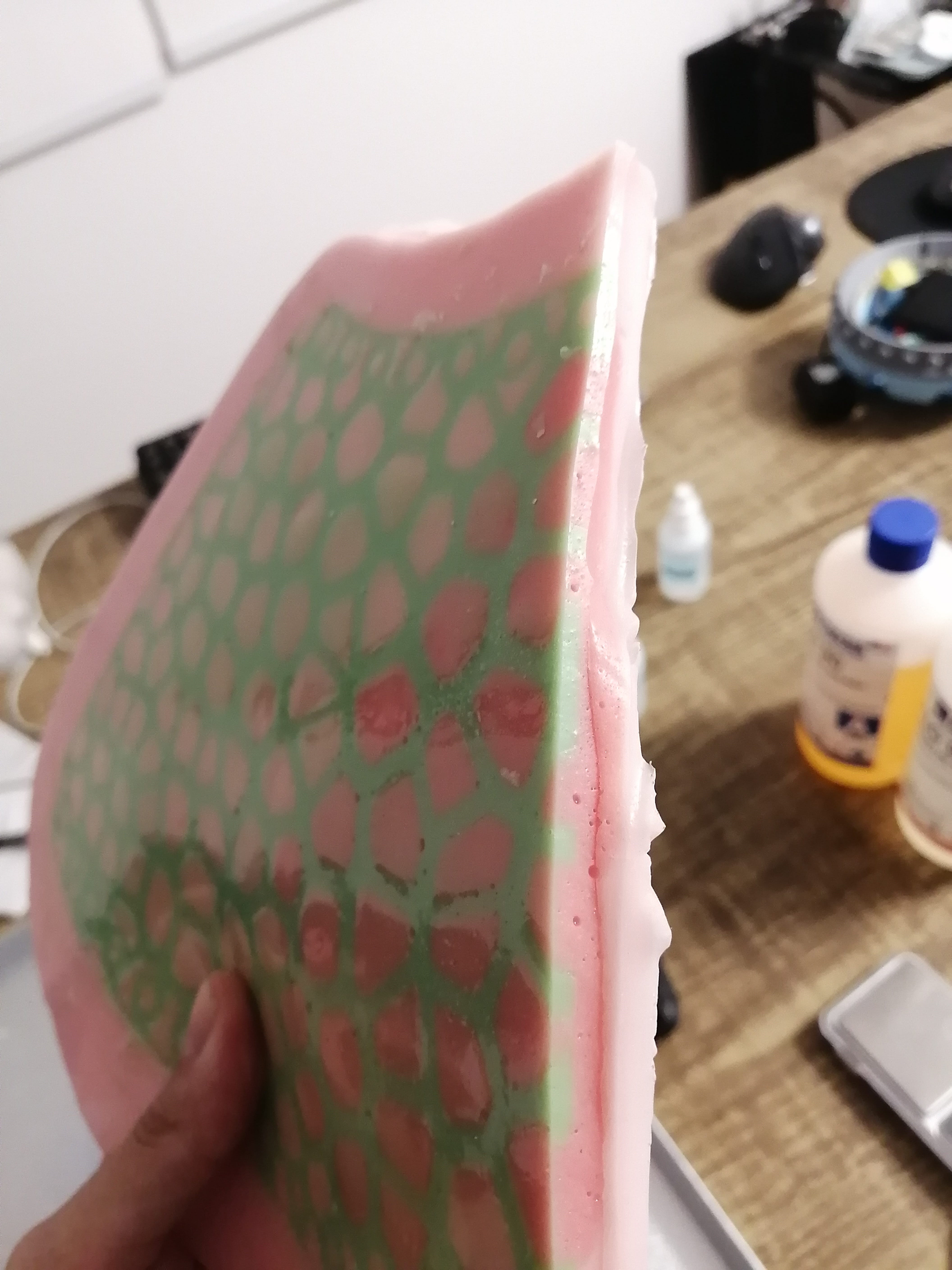
It was a success, and the peeling of the skin was a very satisfying process.
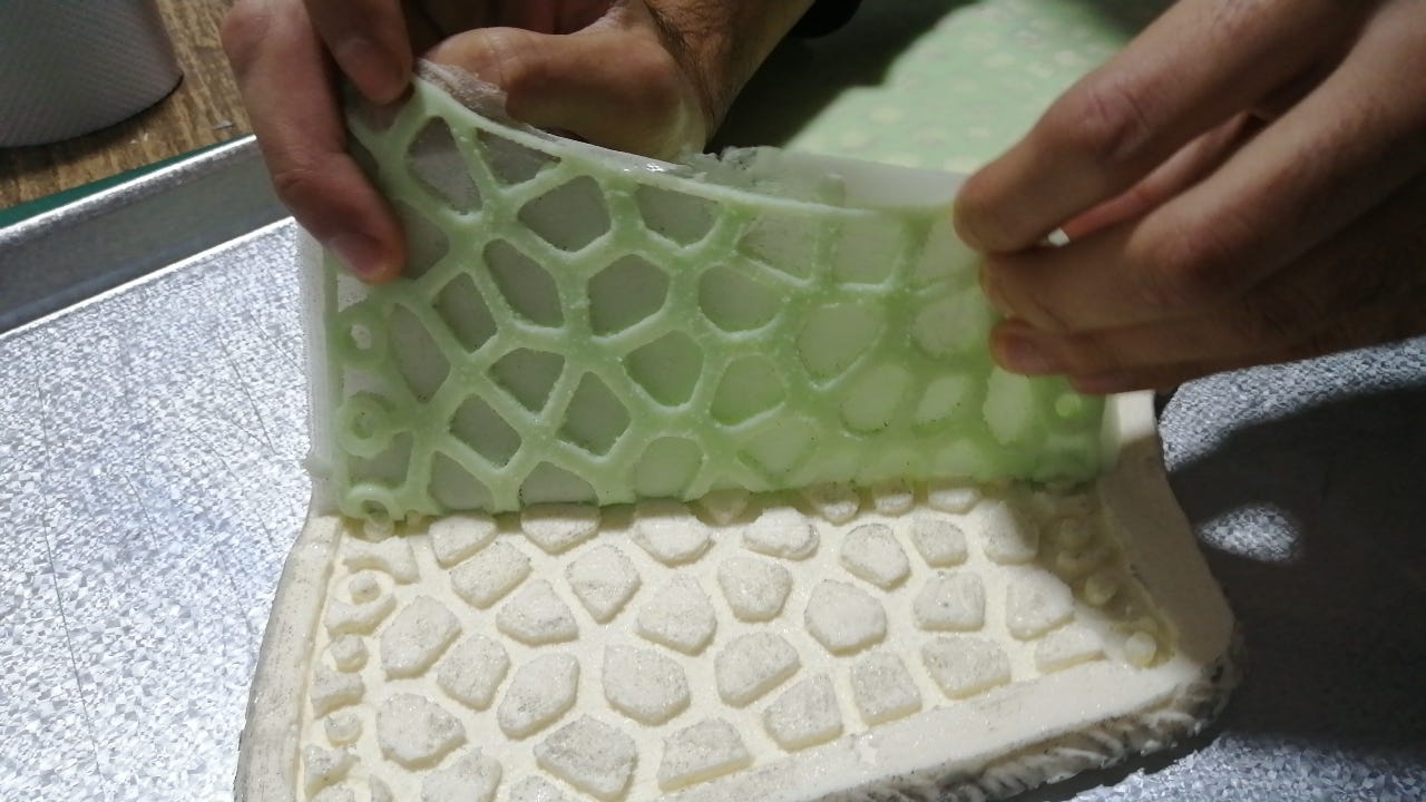
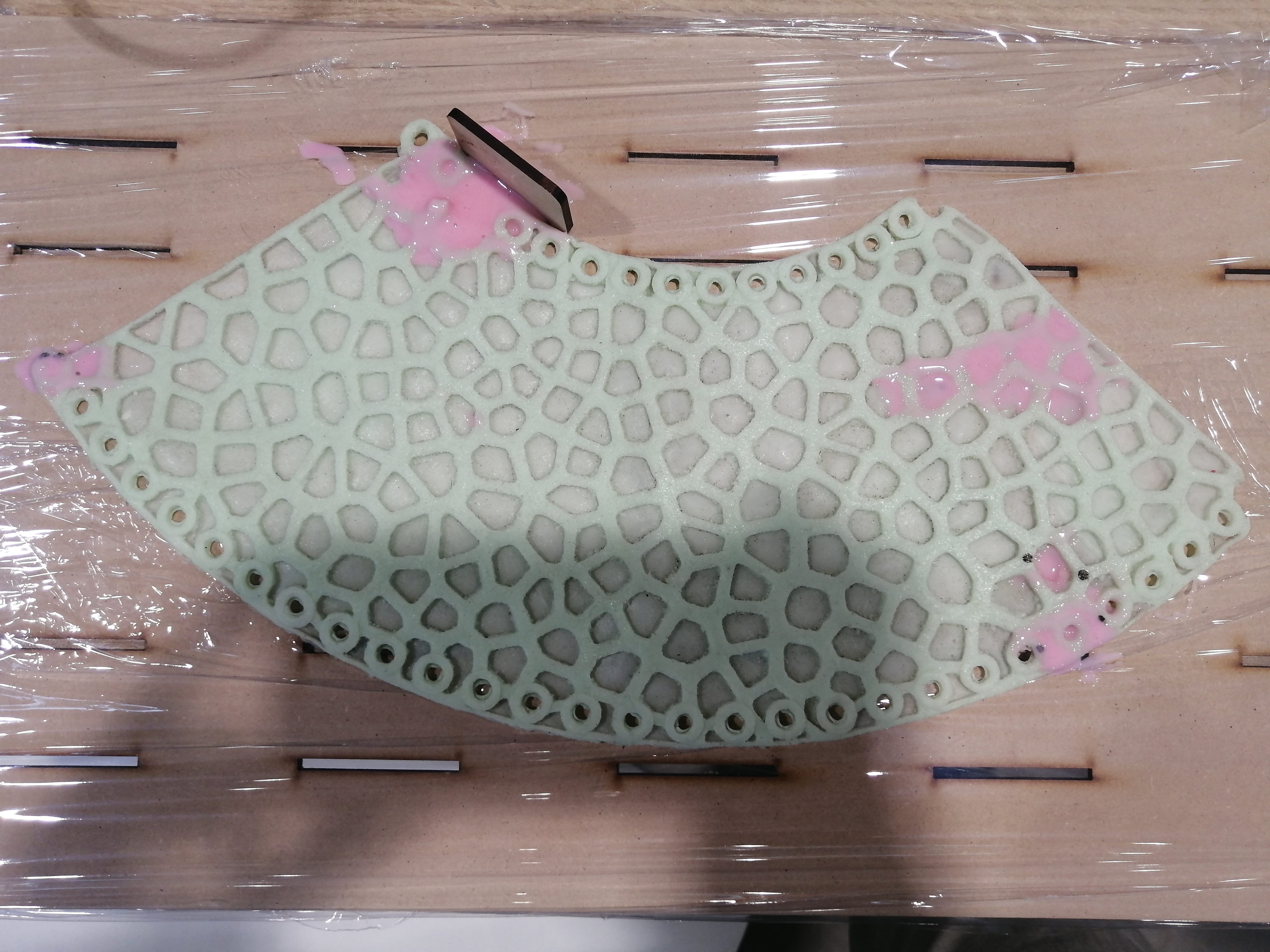
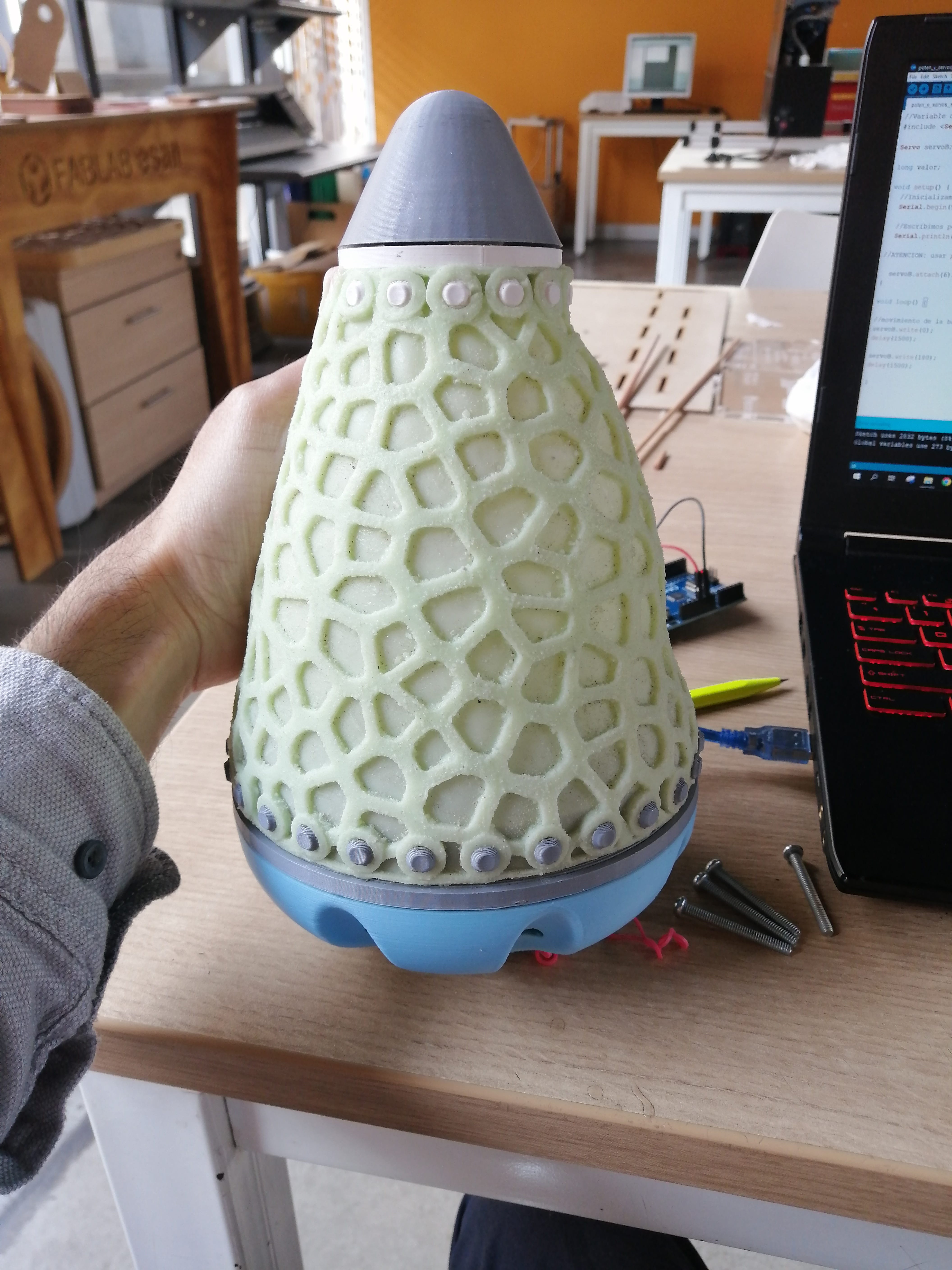
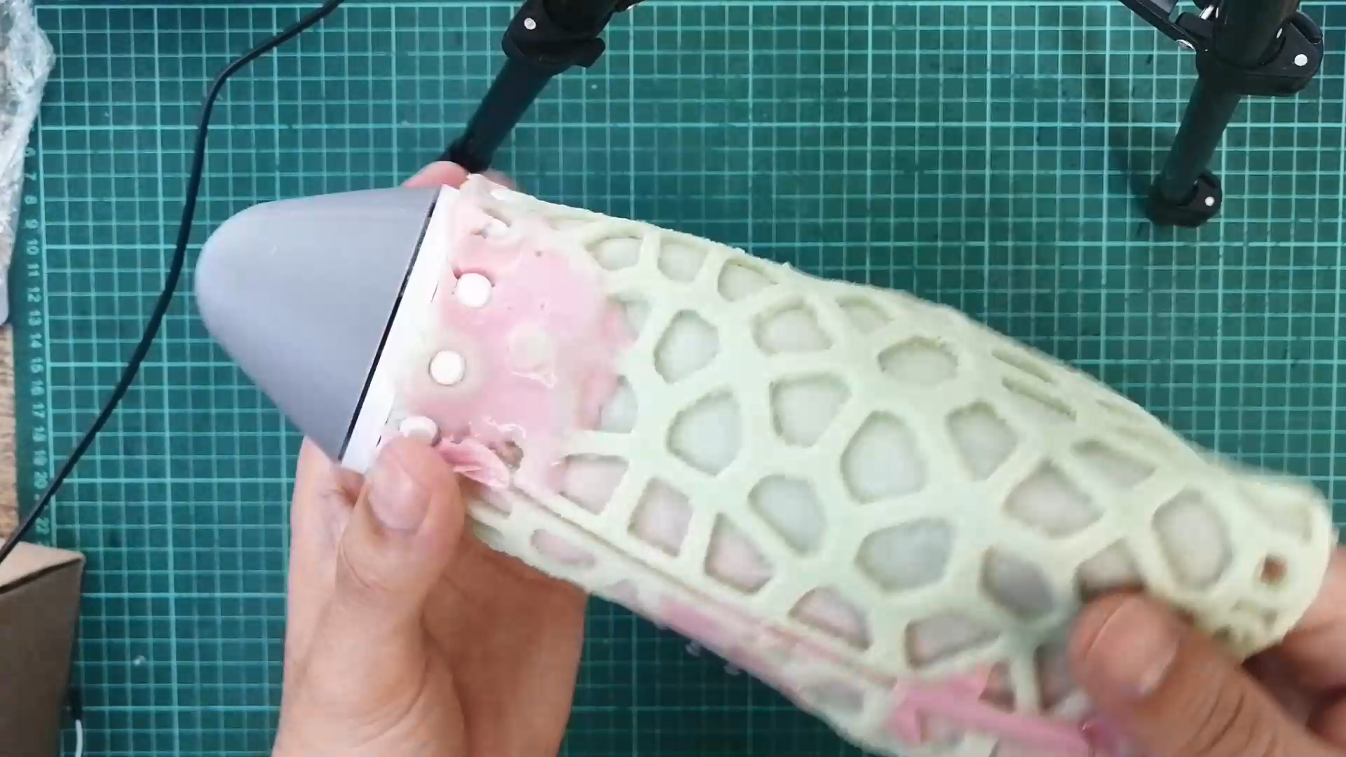
The skin is ready! only minor flashing to remove, but you can already see the translucent effect that I wanted!
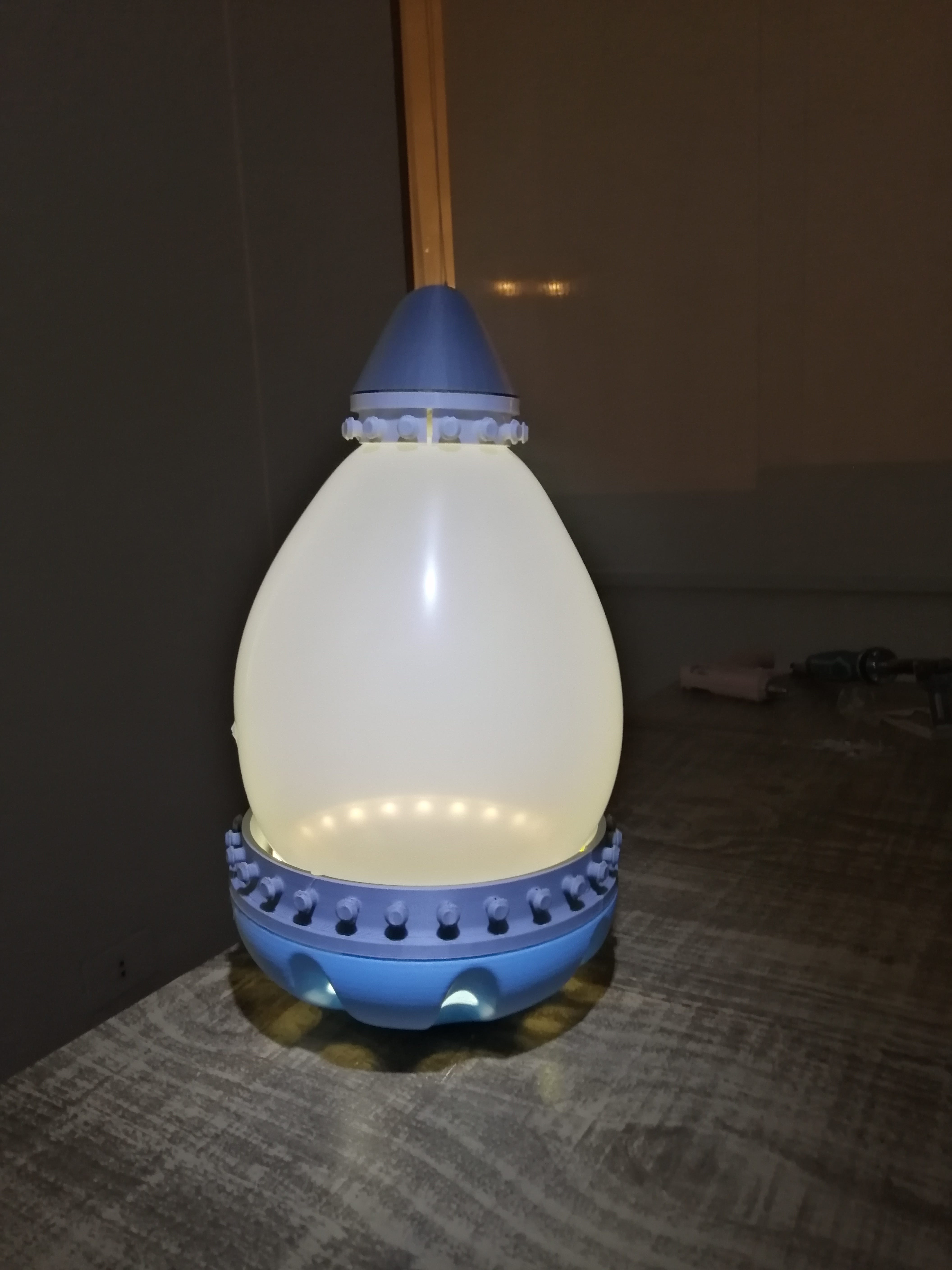
This is the final assembly test with the ballon inside as a diffuser and support
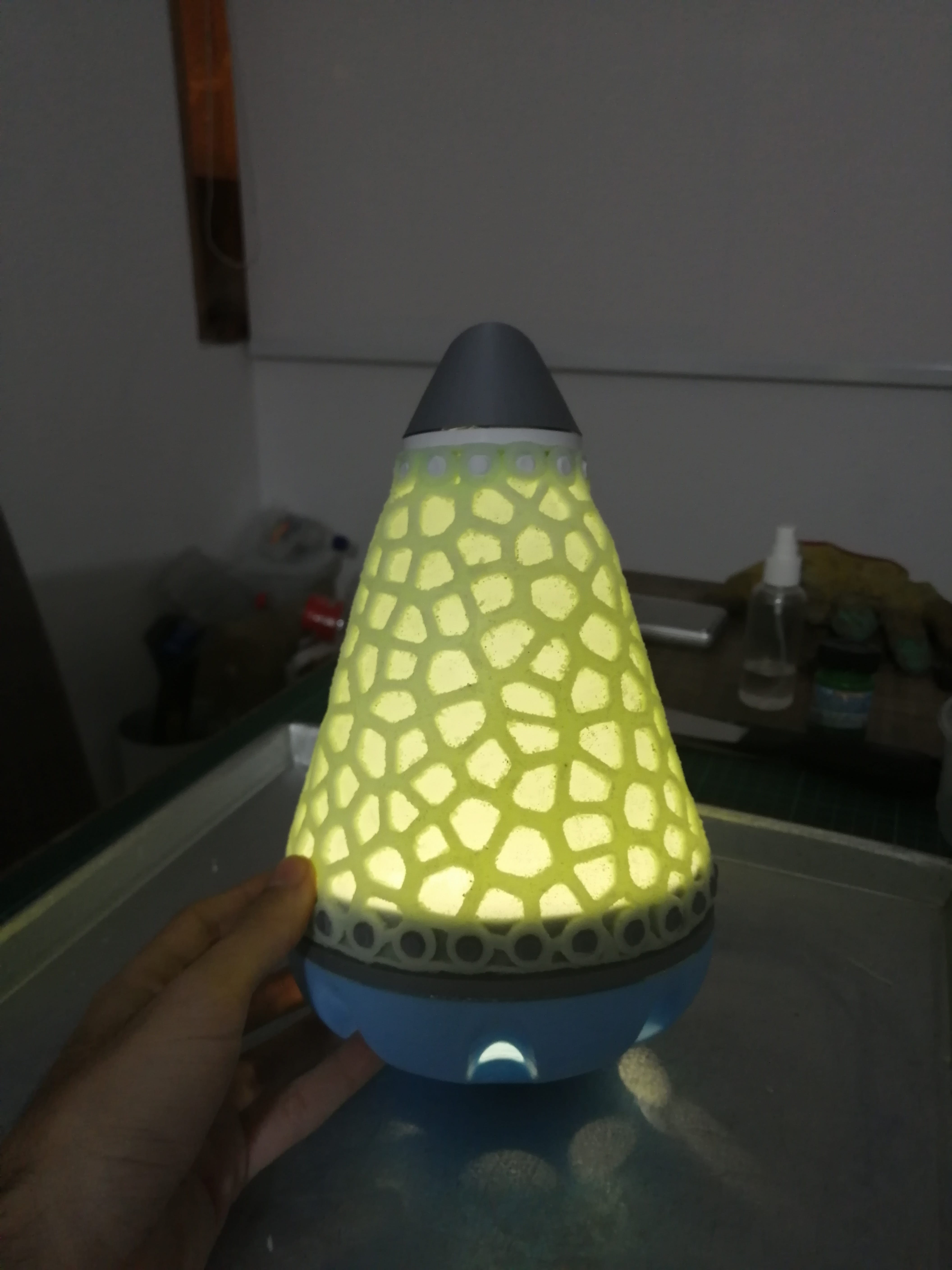
Look at it swing!
The skin suffered some damage as been in storage for a long time, and some wear and tear appeared, even one of the support holes went missing! I attempt to fix these by pouring some more silicone. Also as the skin is made from a flat mold, there is no closure on the back, which causes some light leaks, and the diffuser does not fit very well.
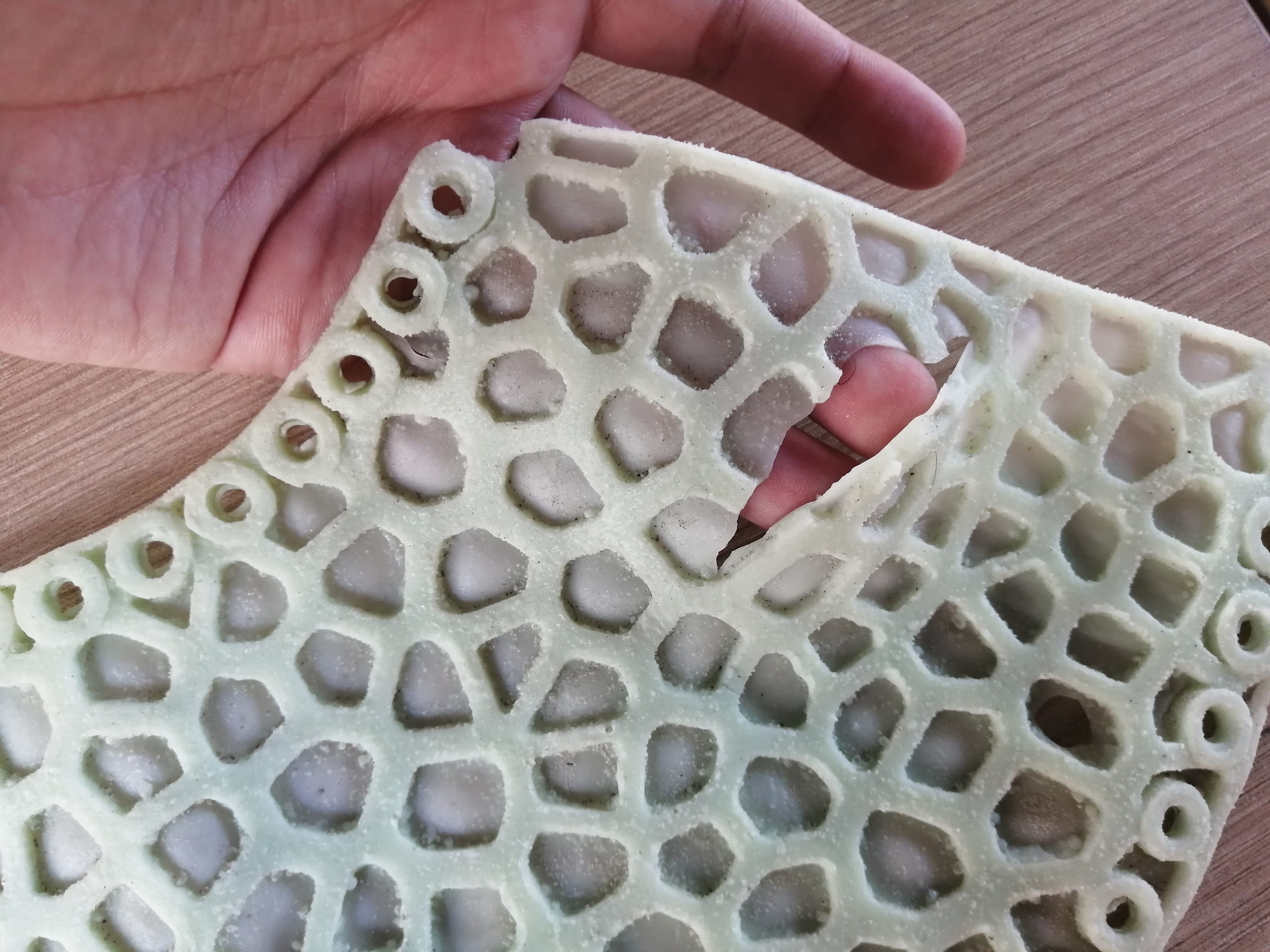
A bit messy, but it worked fine, the second step was to turn the skin and close the seam by pouring silicone on both ends. Sadly the only silicone I had available had a red catalyzer and thus the pink color.
The internal mechanism
The device as a tactile interface should move and light up to communicate with the user, the light effects are achieved with a Neopixel ring, and some of these effects were tested in the Embedded programming assignment, and later explored in the Interface and application programming assignment.
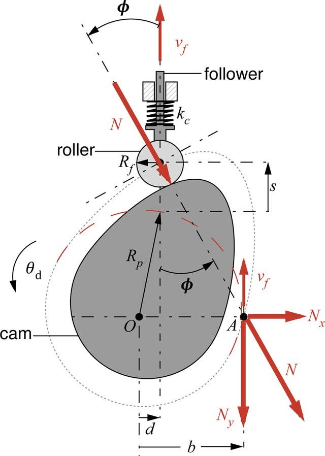
The moving stimuli are made with a servo and a cam and follower mechanism that compresses a ballon and creates a pulsating effect. The servo movements and control were tested at the Output devices assignment.
The idea for the setup is to place the servo in a central position (as it is heavy) in the base, attached to the servo gear will be a Cam and follower mechanism to move a base up and down to replicate a pulsating movement.
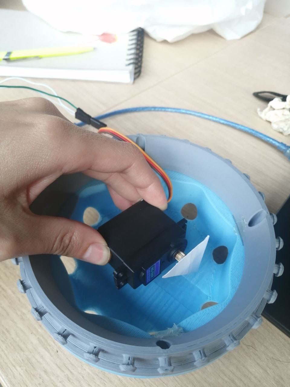
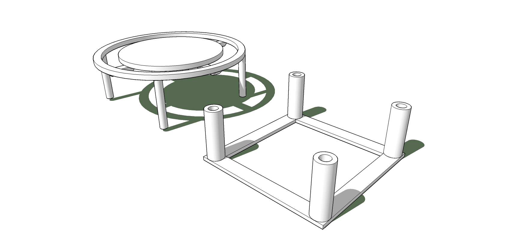
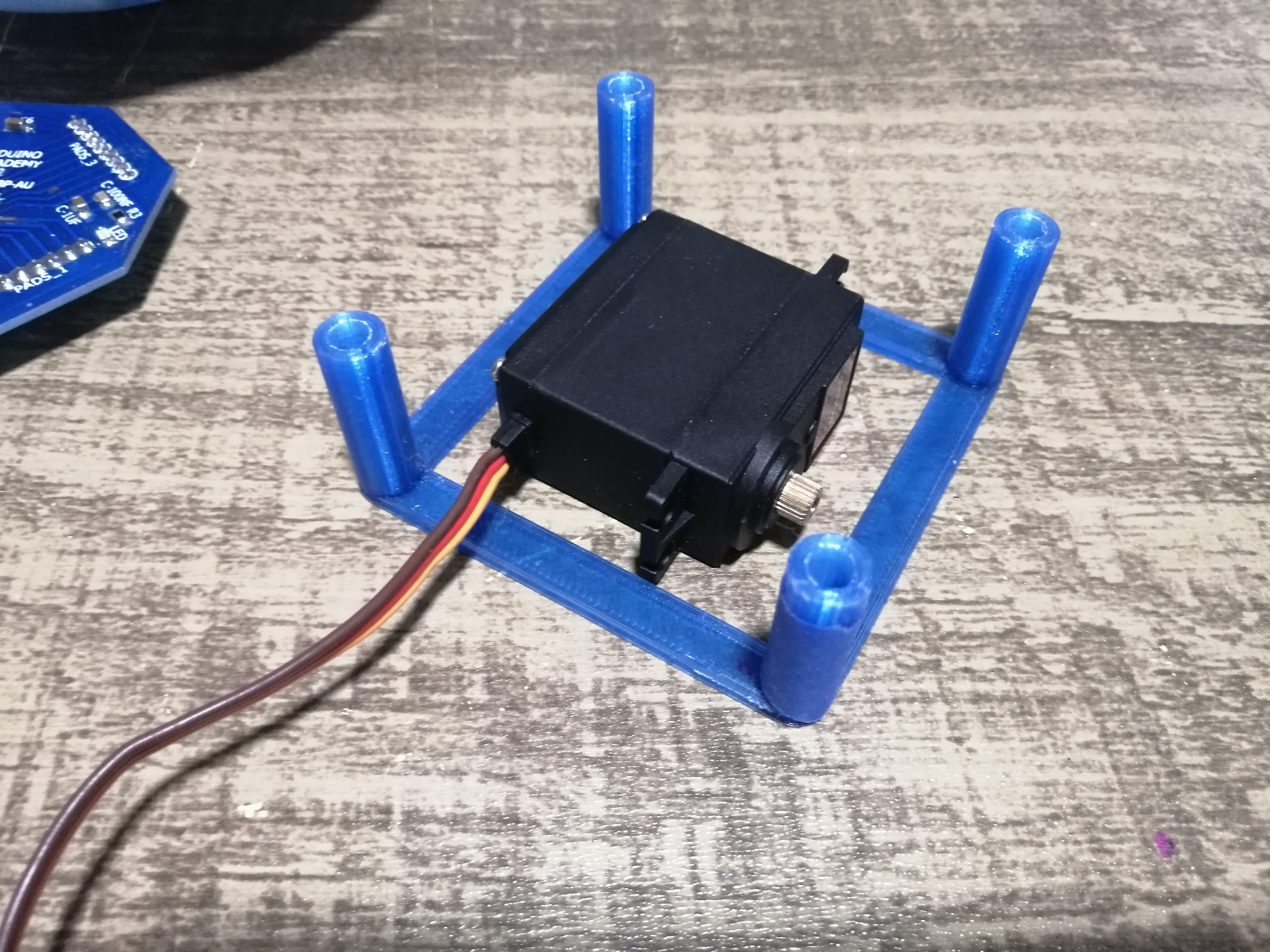
So, the internal mechanism should hold the servo, the Neopixel ring, the 9V battery as a power source, and the Octoduino Board. I made a quick design in Sketchup and 3D printed it to test the concept.
The design consists of two parts, the one on the left holds the Neopixel ring and is the contact surface with the balloon, this is the part that moves up and down and has some pins that go inside the other part. The part on the right goes attached to the base already printed, this part holds the servo and the Octoduino Board.
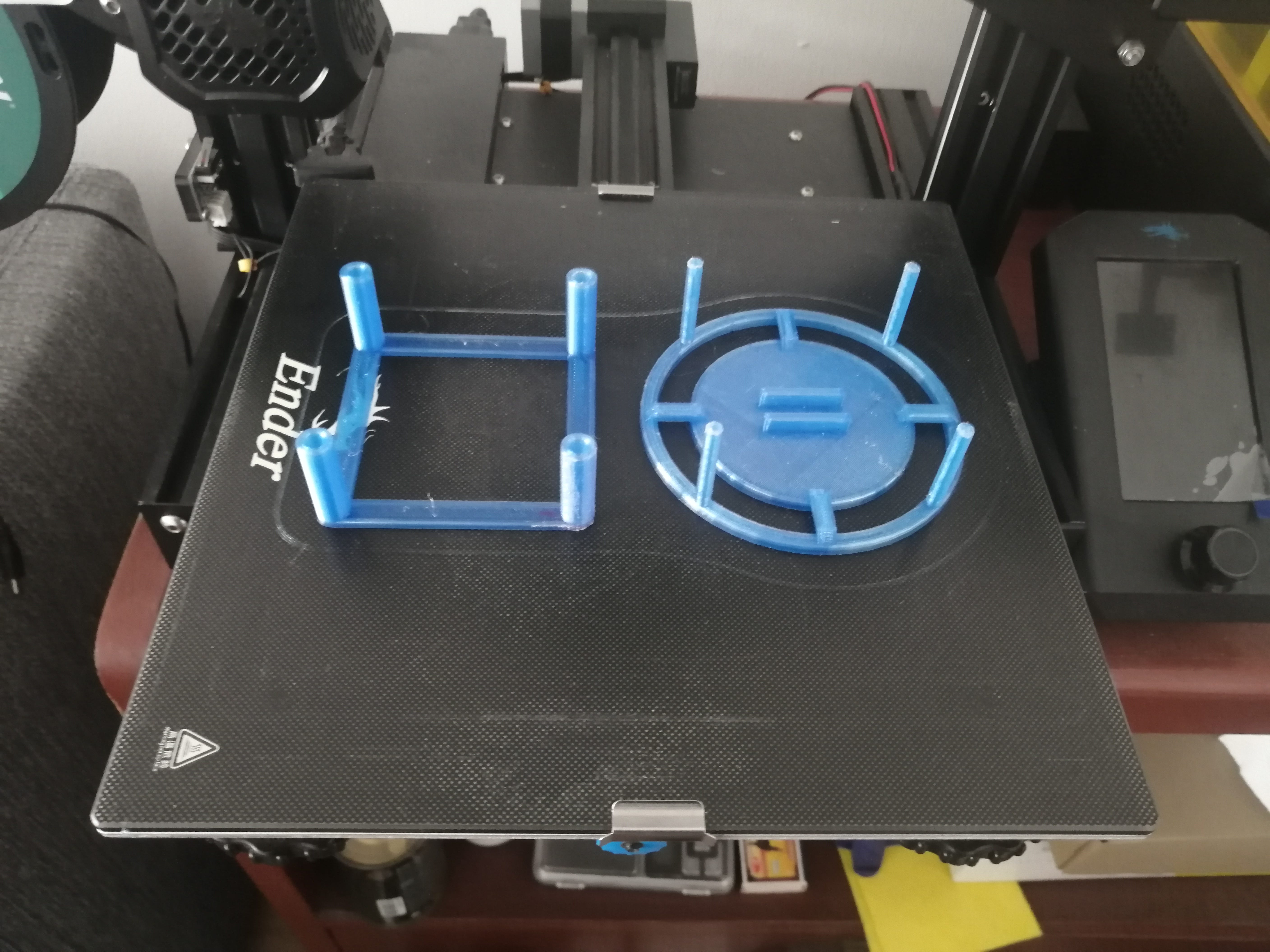
After some minutes of printing, I have the first prototype.
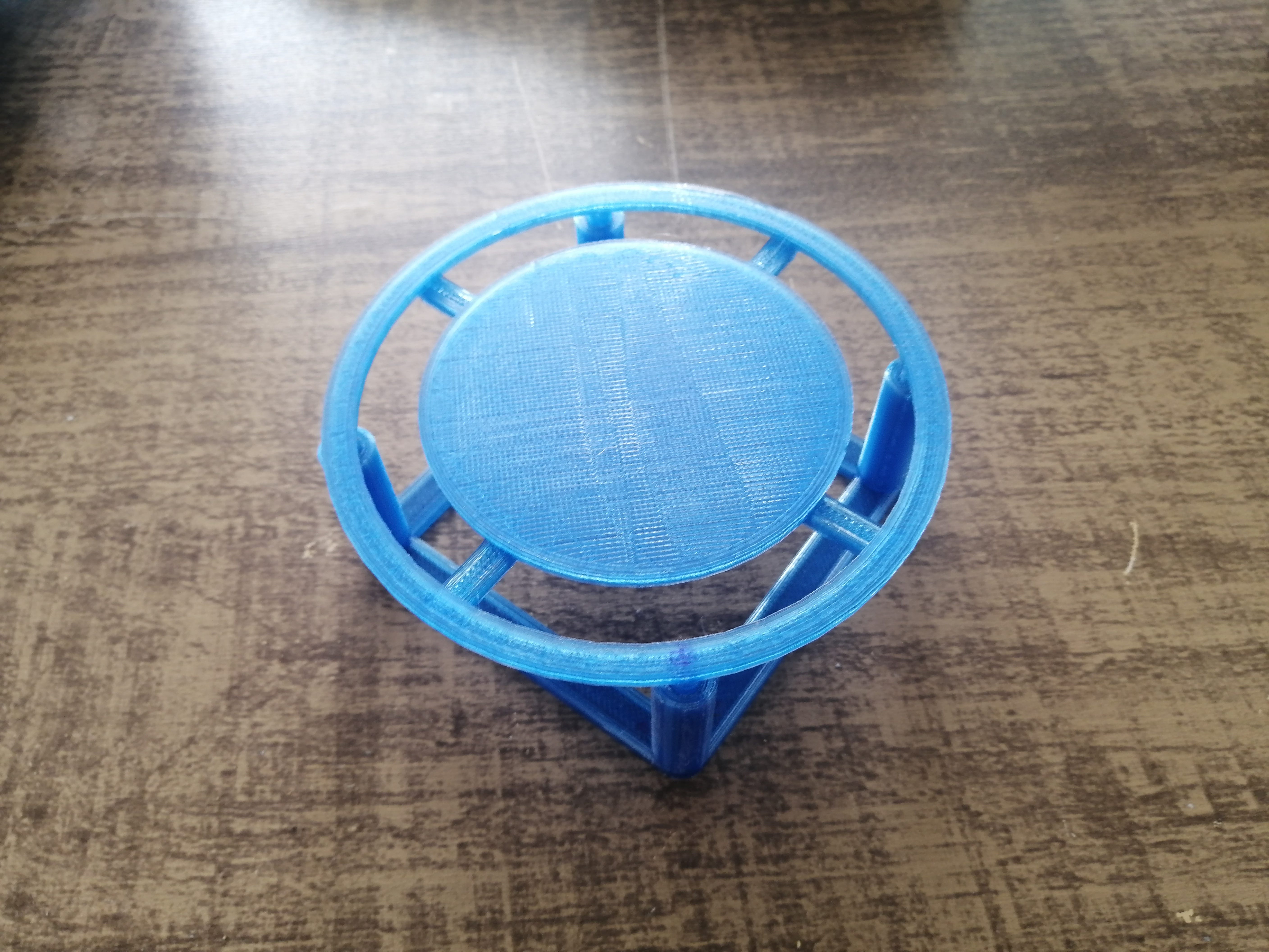
This is the final position of the two parts of the mechanism inside each other. The tolerance of the pins is too tight so I’ve had to do a light sanding to make a better sliding movement.
The position of the mechanism inside the base goes as follows, I calculated carefully not to obstruct the holes already in the base, as these will hold a switch and the pulse sensor.
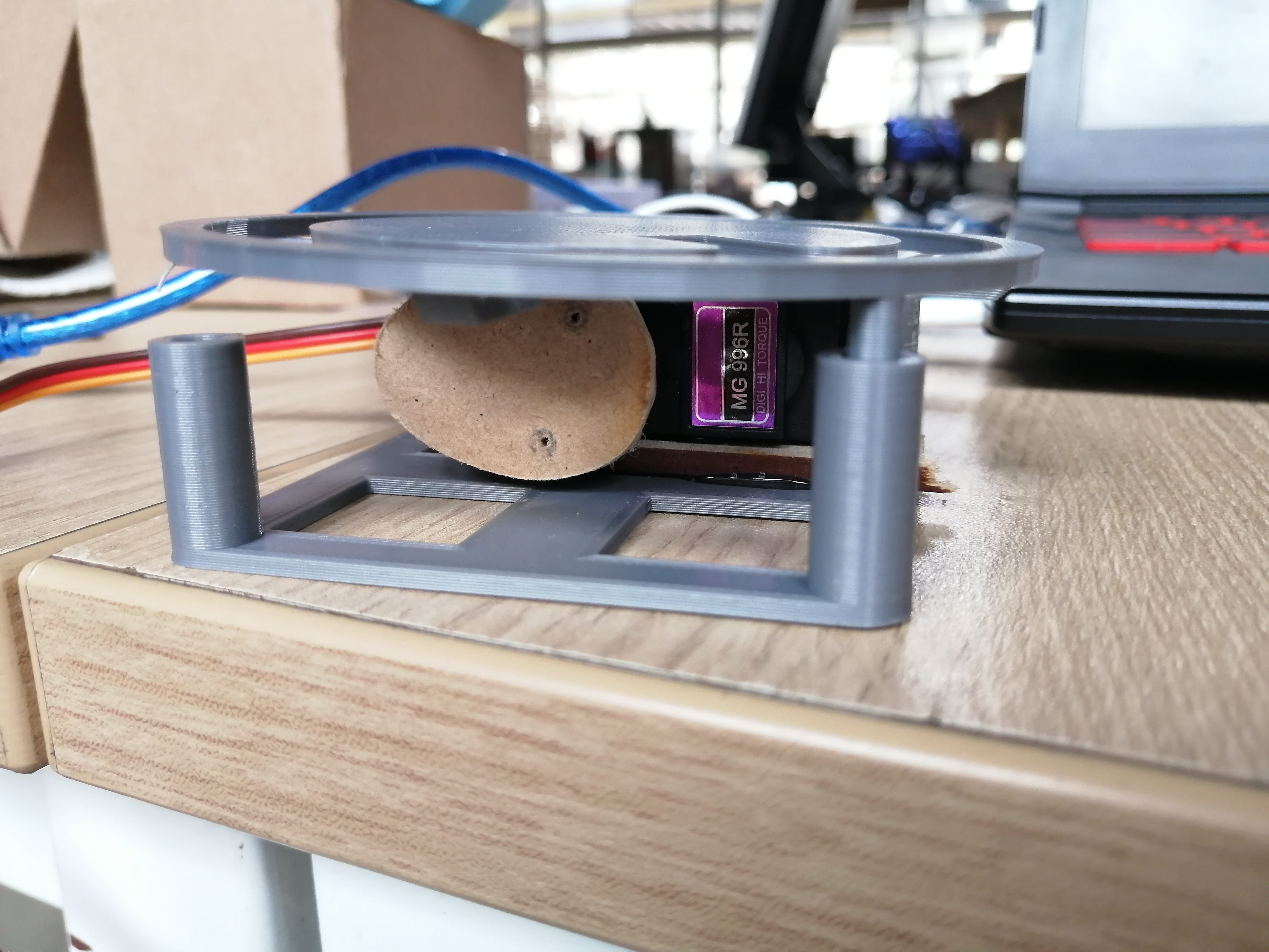
The servo should be positioned something like this, and directly attached to the base, this position will make the weight centered to get a better balance when the base tumbles, but it might cause problems with the cam as the contact point will not be centered.
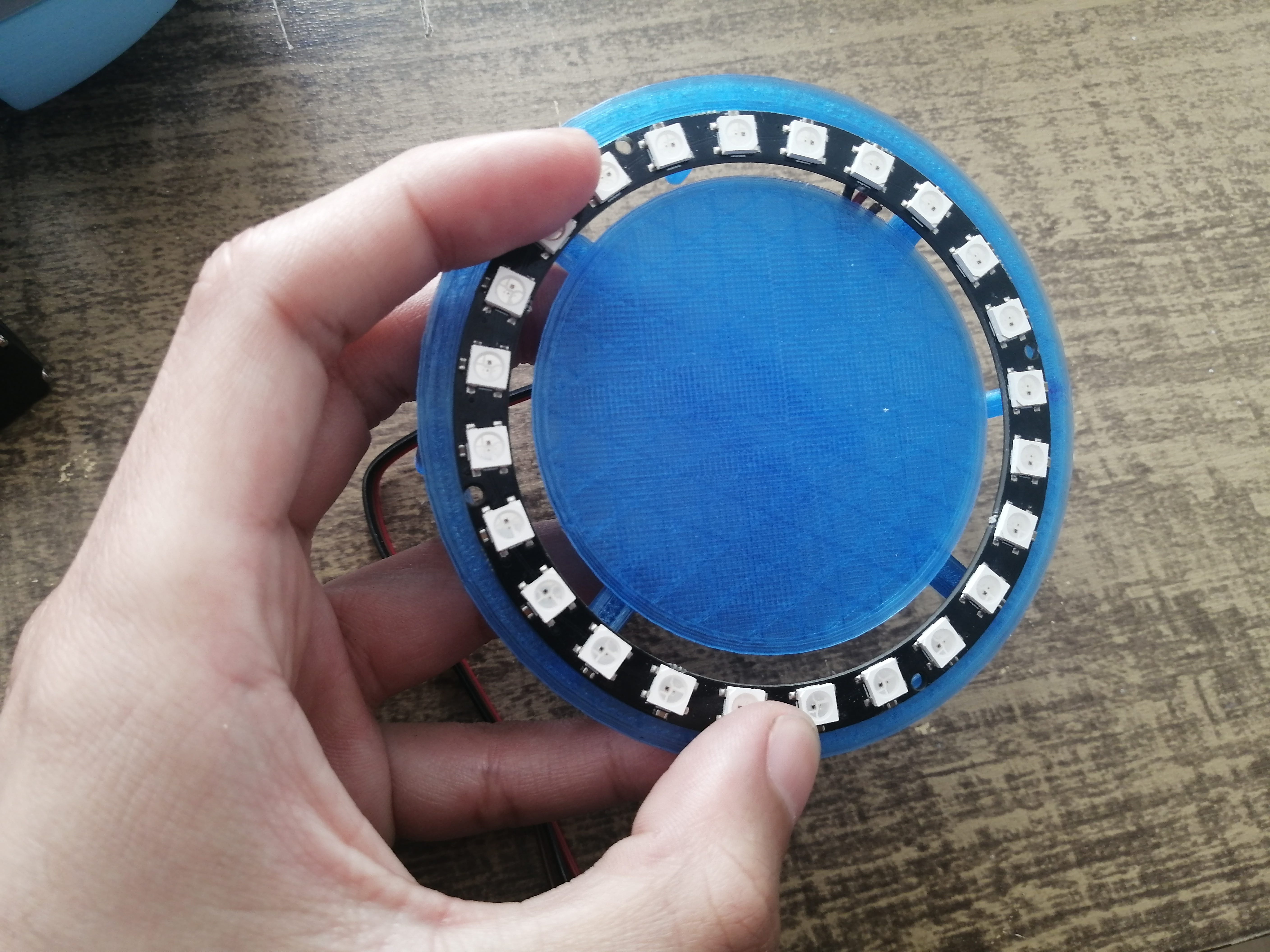
The Neopixel ring goes into the part and holds by press-fit, the recess is measure to get a flat contact surface.
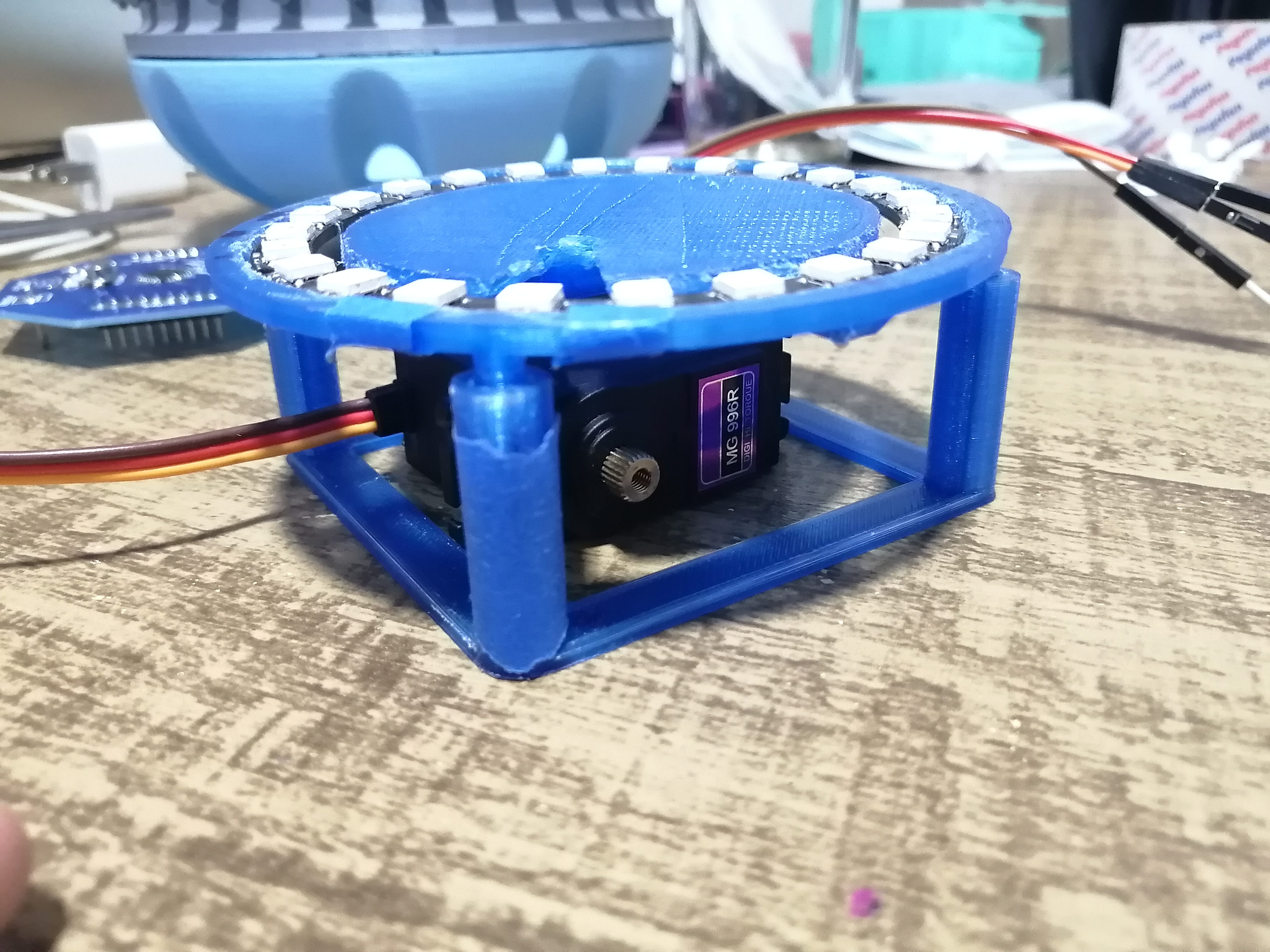
This is the test fit for the servo and the Neopixel ring, the cam is not attached yet.
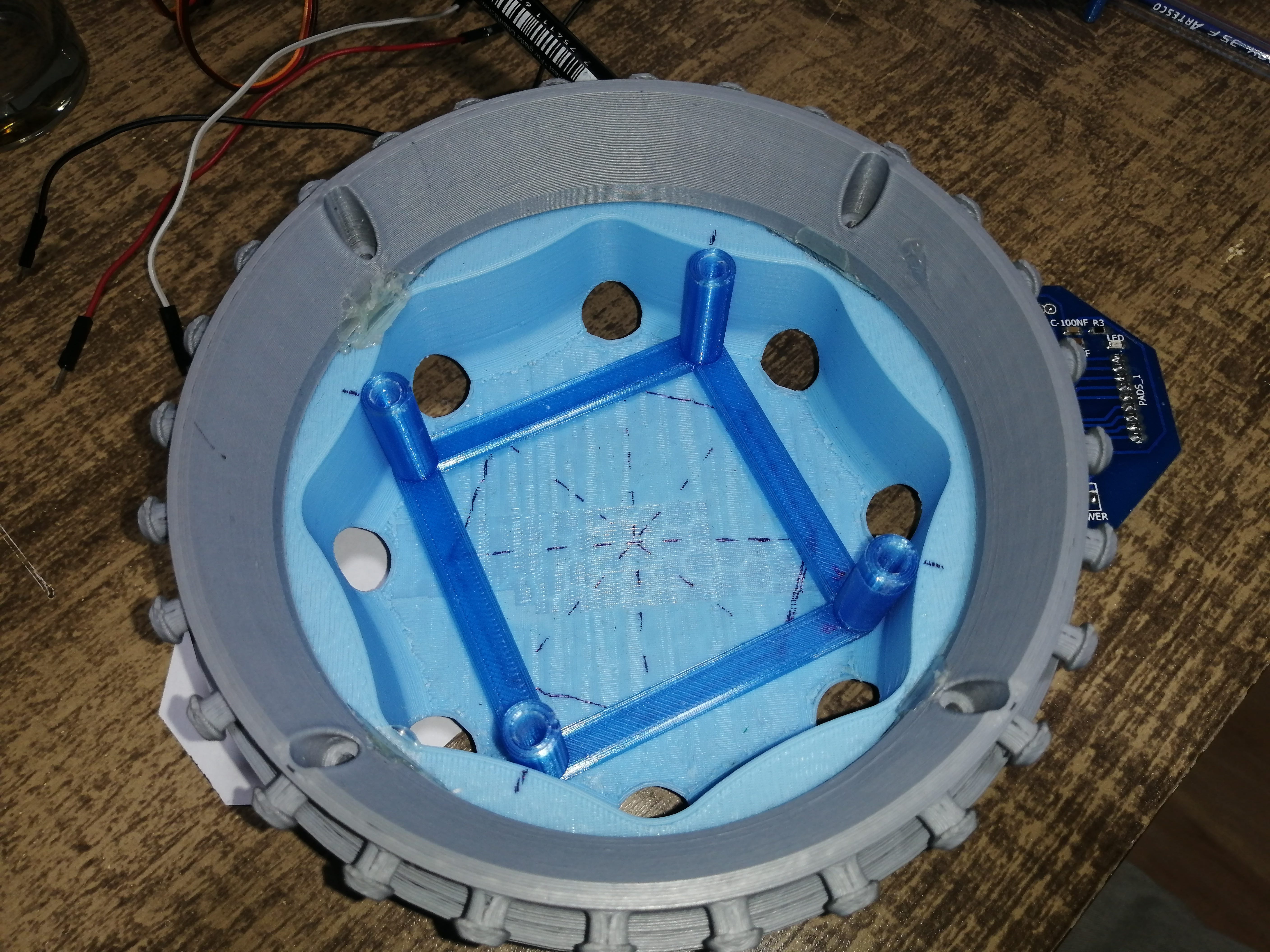
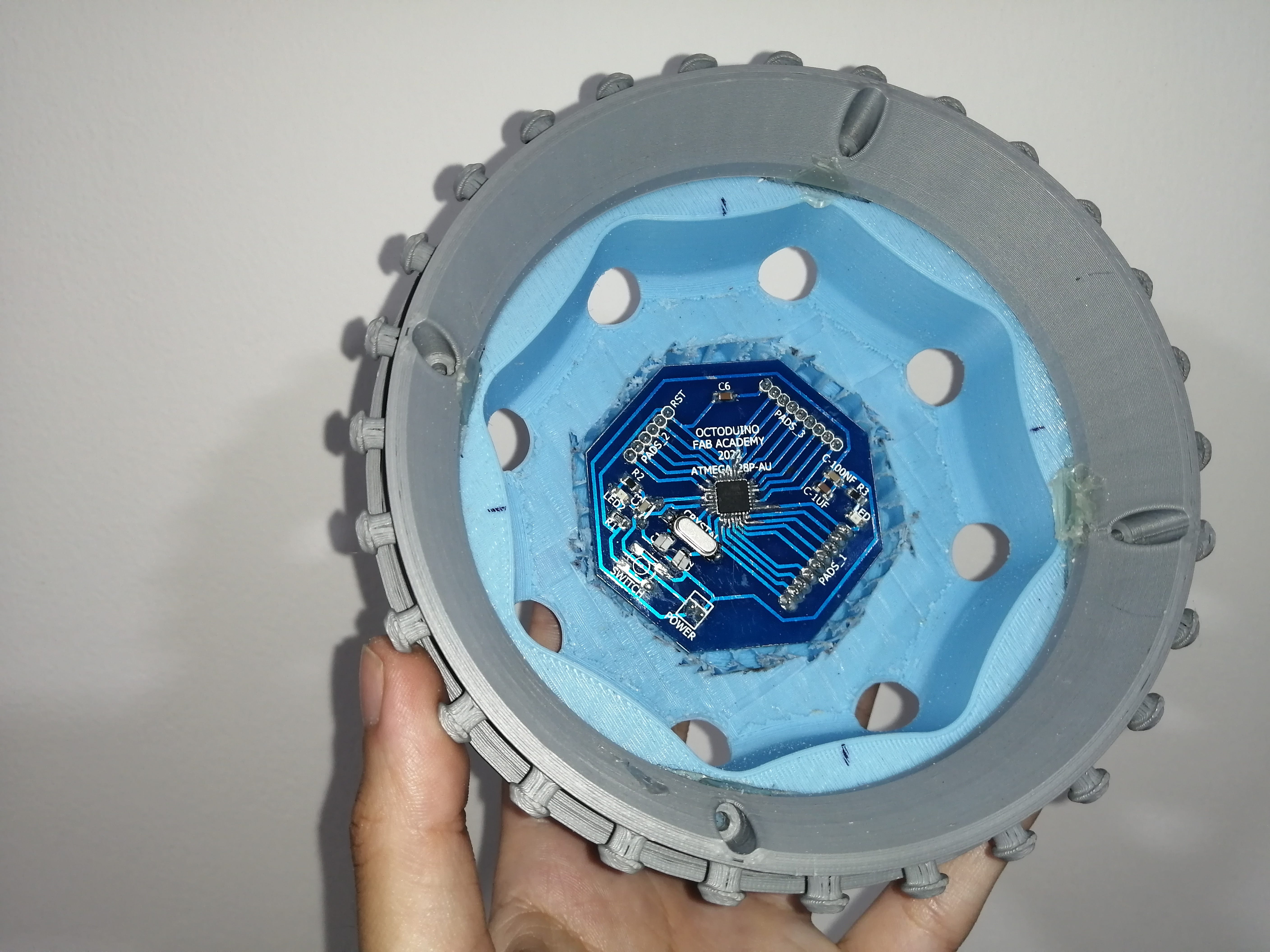
The original plan was to mount the Octoduino board to the base and under the servo, but the space available is not enough, so after some consideration, I decided to hollow out the base to house the board.
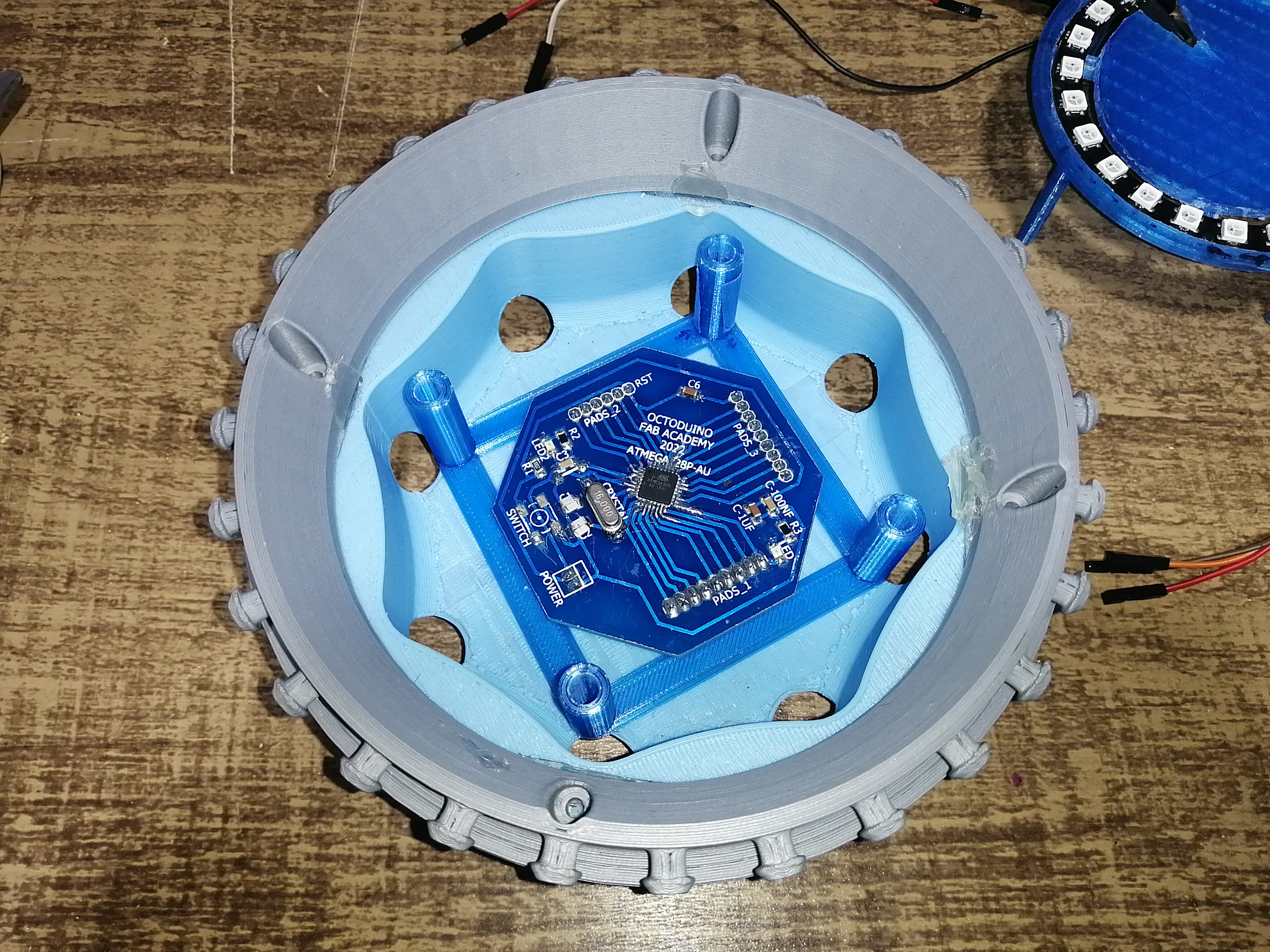
I trimmed out the base by making a template of the board and then cut out with a rotary tool and clean out the edges by sanding, not one of my proudest digital fabrication moments, but it works to prove the strategy.
Here is clear as why the Octoduino board has 8 sides, to best fit the base. ;)
This should be the position of the board, it might need additional space for the cables to go in and out for the sensor and actuators.
As the base is hollowed out the servo does not have a base to hold, so the mechanism needs a second iteration, I already do not know the exact position of the servo and did not test the movement so this is still a work in progress.
I made a quick test for the cam by laser cutting a piece and then sanded it down to make it smoother or better calibrate the movement.
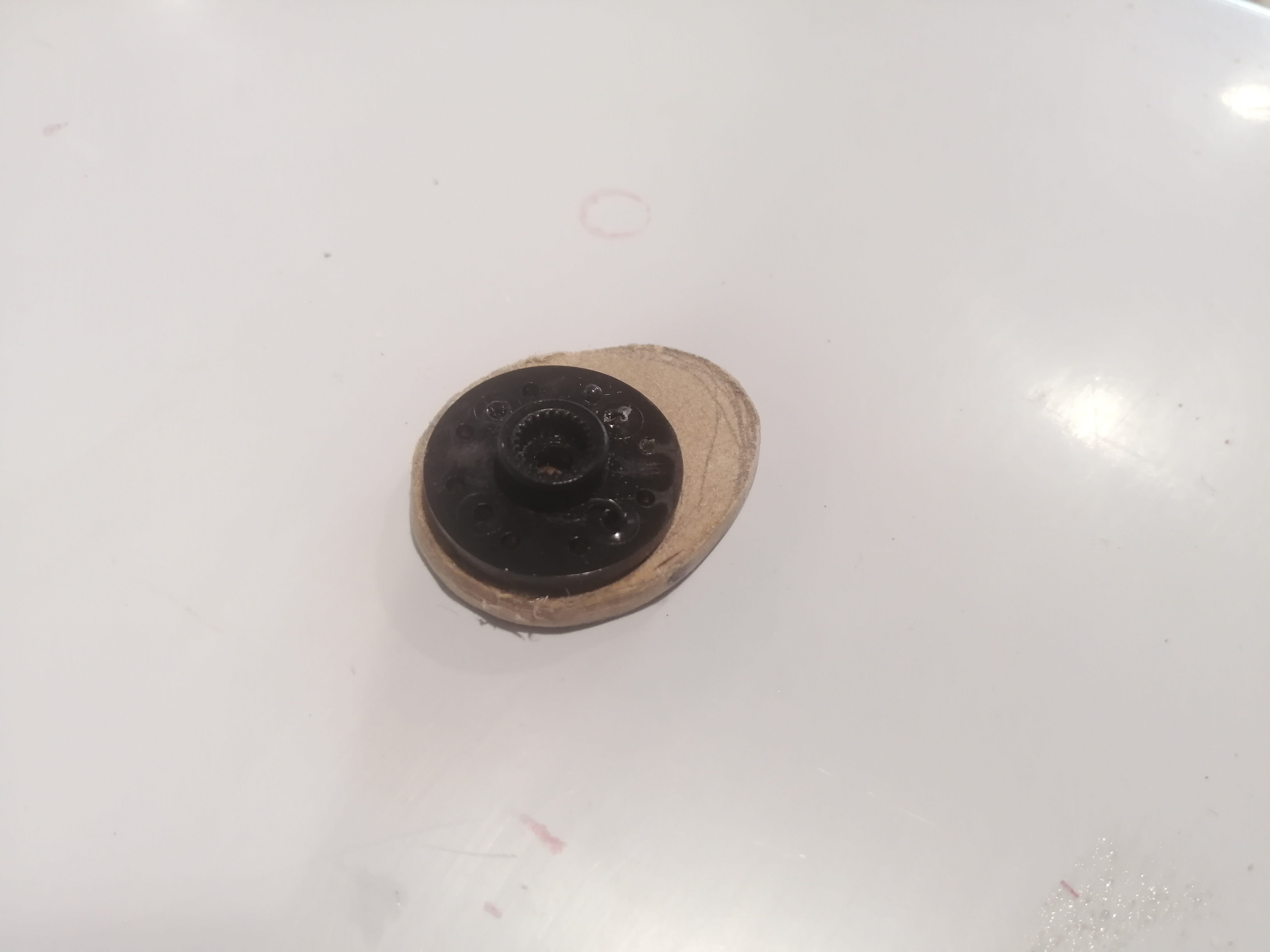
This is the second attempt at the mechanism with the movement test. I didn’t have the best results as there was too much friction with the 3D-printed parts and the platform was moving off-centered and sometimes got stuck, even though I repositioned the servo to center the cam additional changes are needed.
After some tests I realized that to get smoother movement the 3D printed pins will not be an option, and also that with some sort of compression, the movement translation from rotational to linear was better, this compression will be made by the balloon, but I added some rubber bands to give it help. Here is the final mechanism with wooden pins and the Neopixel ring mounted.
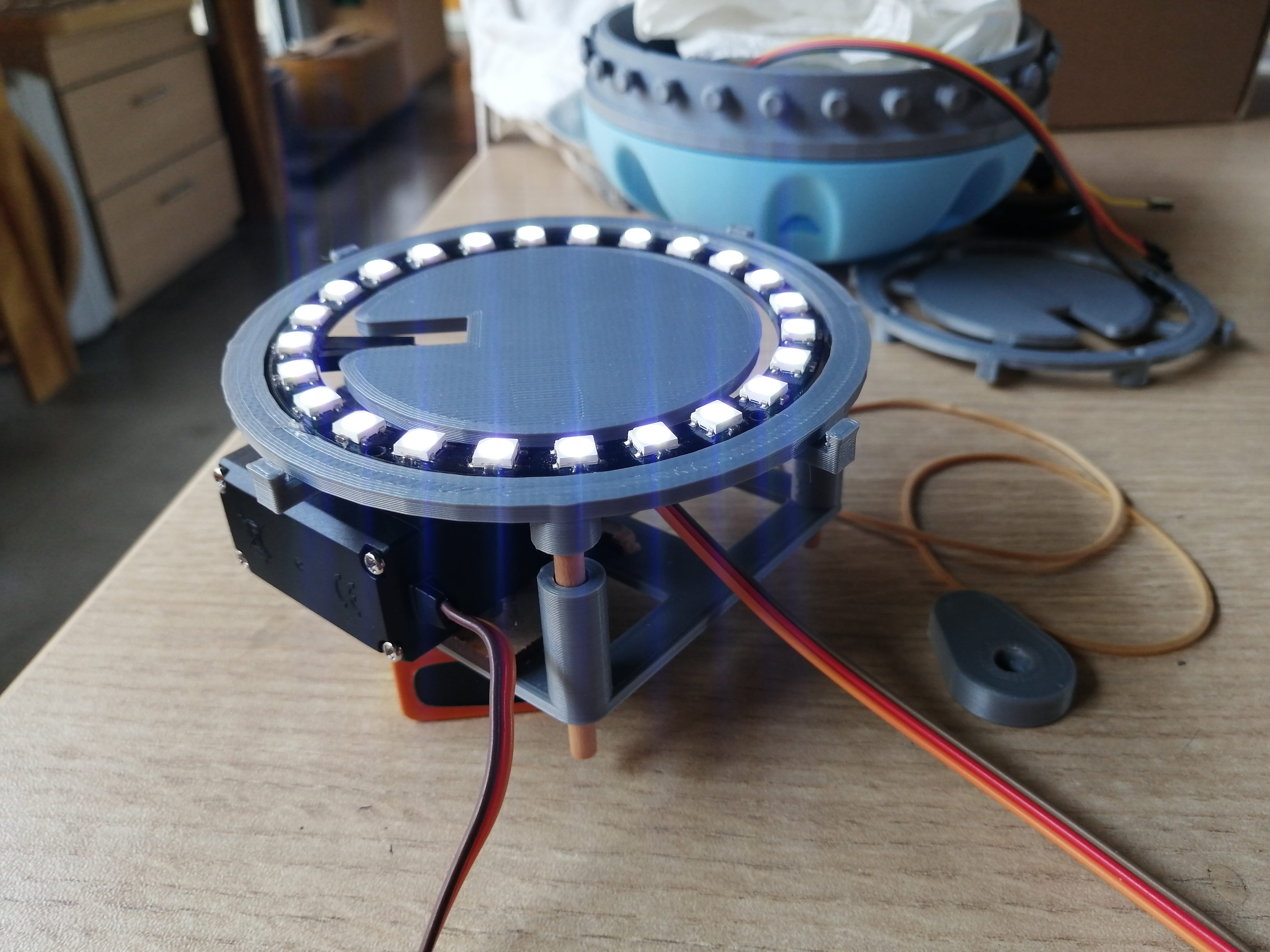
Here is a short video of all the attempts and the final result with the mechanism mounted inside, the pulsating movement is really subtle in the video, but in real life is better perceived, also when you hold the lamp the pulsating effect is clear, and mimics the breathing rhythm.
The mechanism inside the device and the final result:
The electronics and programming
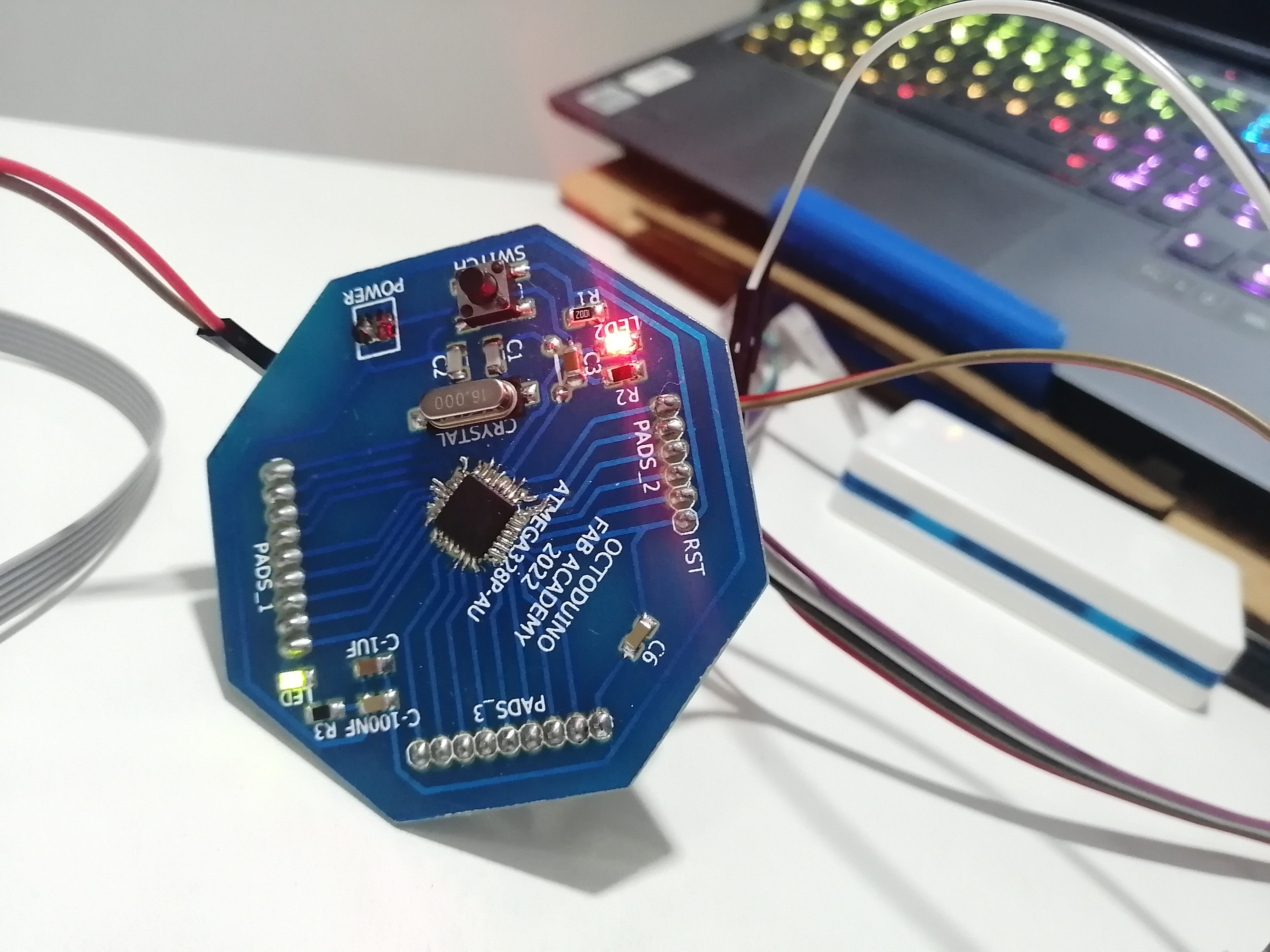
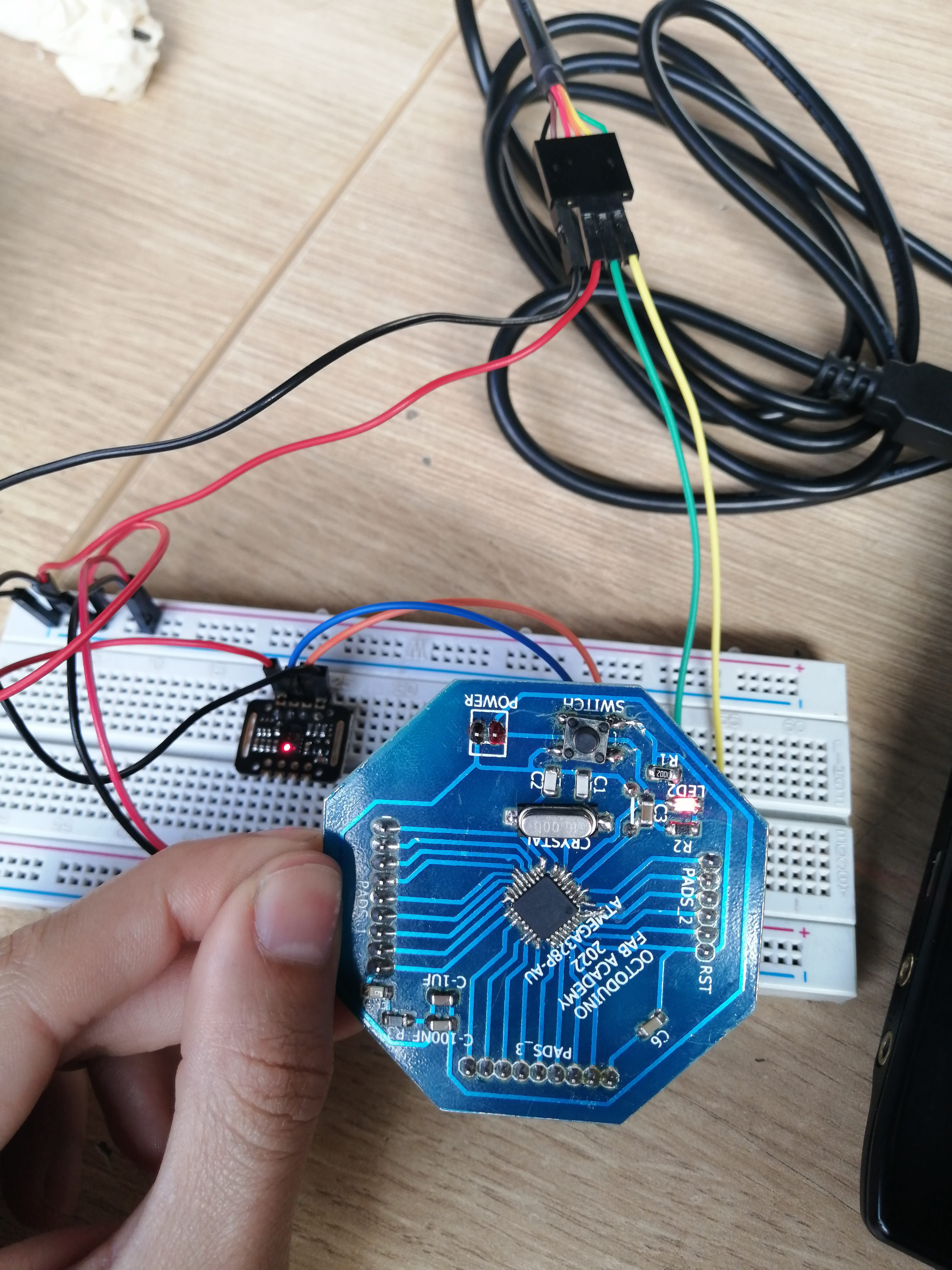
The most important part of the device is the microcontroller, this is called the Octoduino and was made during Embedded programming week because the board I made in Electronics design week got lost during the lockdown, so I created a new one, this time using an ATMEGA328P instead of the classic ATtiny44. This board is based on the SatshaKit design developed by Daniele Ingrassia.
This board also helped me with other assignments but it was planned as my Final project board, this is why it has an octagonal design to fit the base.
Another important electronic component is the Pulse sensor, which is explored in the Input devices assignment, This device is mainly intended for wearables. The MAX30102 is the central SMD component, and I got this already mounted on a module. Here is the Datasheet for the component.
This sensor is used to detect blood oxygen and heart rate, and I will use this second capability. First, infrared radiation is sent and reflected by hitting the finger, and then the amount of oxygen in the blood is determined by measuring the wave amplitude. Heart rate is also obtained by analyzing the time series response of this radiation.
This sensor needs to be mounted with the infrared LED facing outside the base and in position to place the finger comfortably while holding the device. The sensor is positioned in one of the holes in the base.
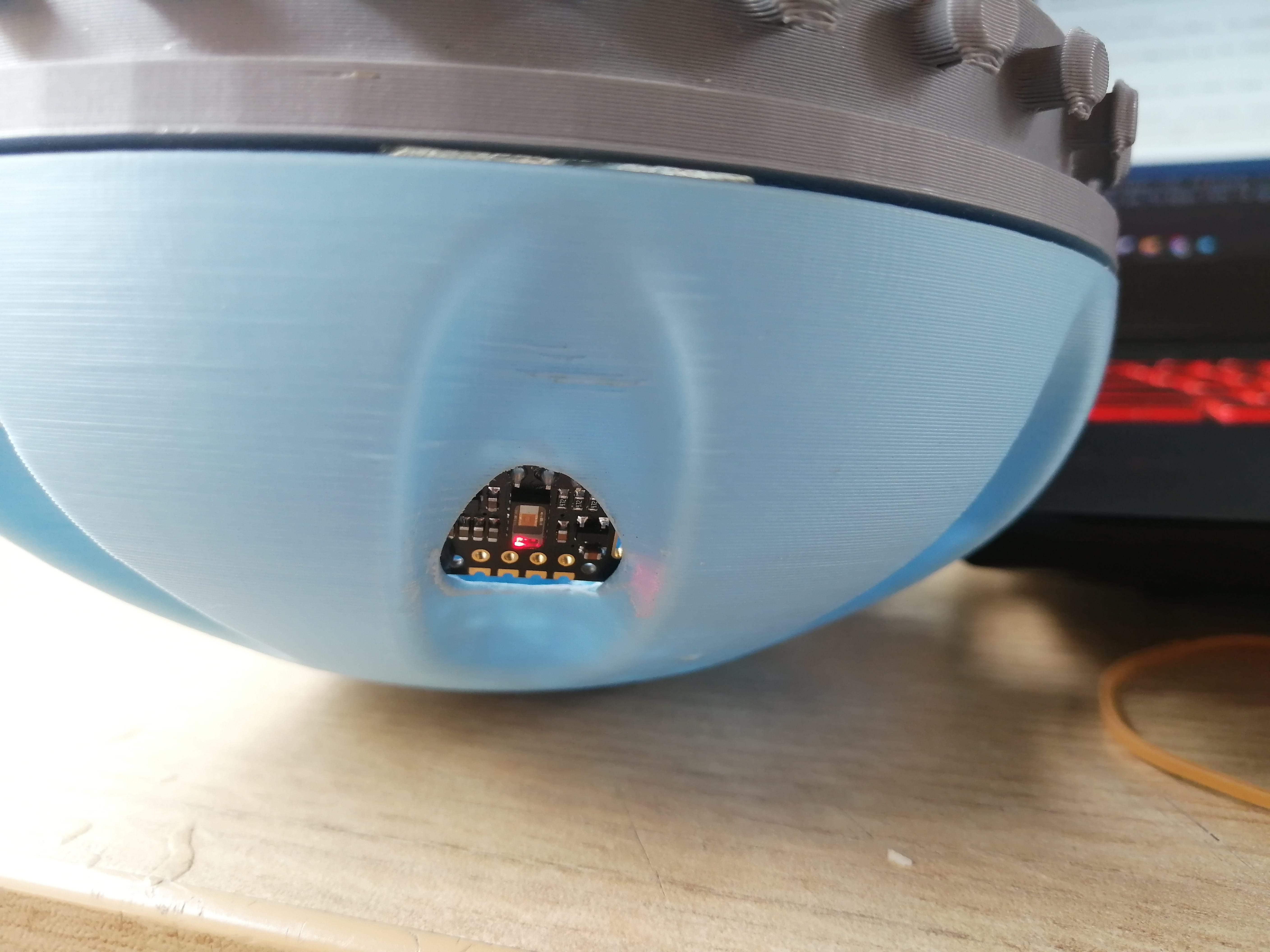
here you can see the sensor through the hole, some slight modification was made to accommodate the sensor because the LED was not close enough to the finger, and the reading was not accurate.
Notice that the design also has these grooves to better hold the device, and these also work by shielding the light from the sensor.
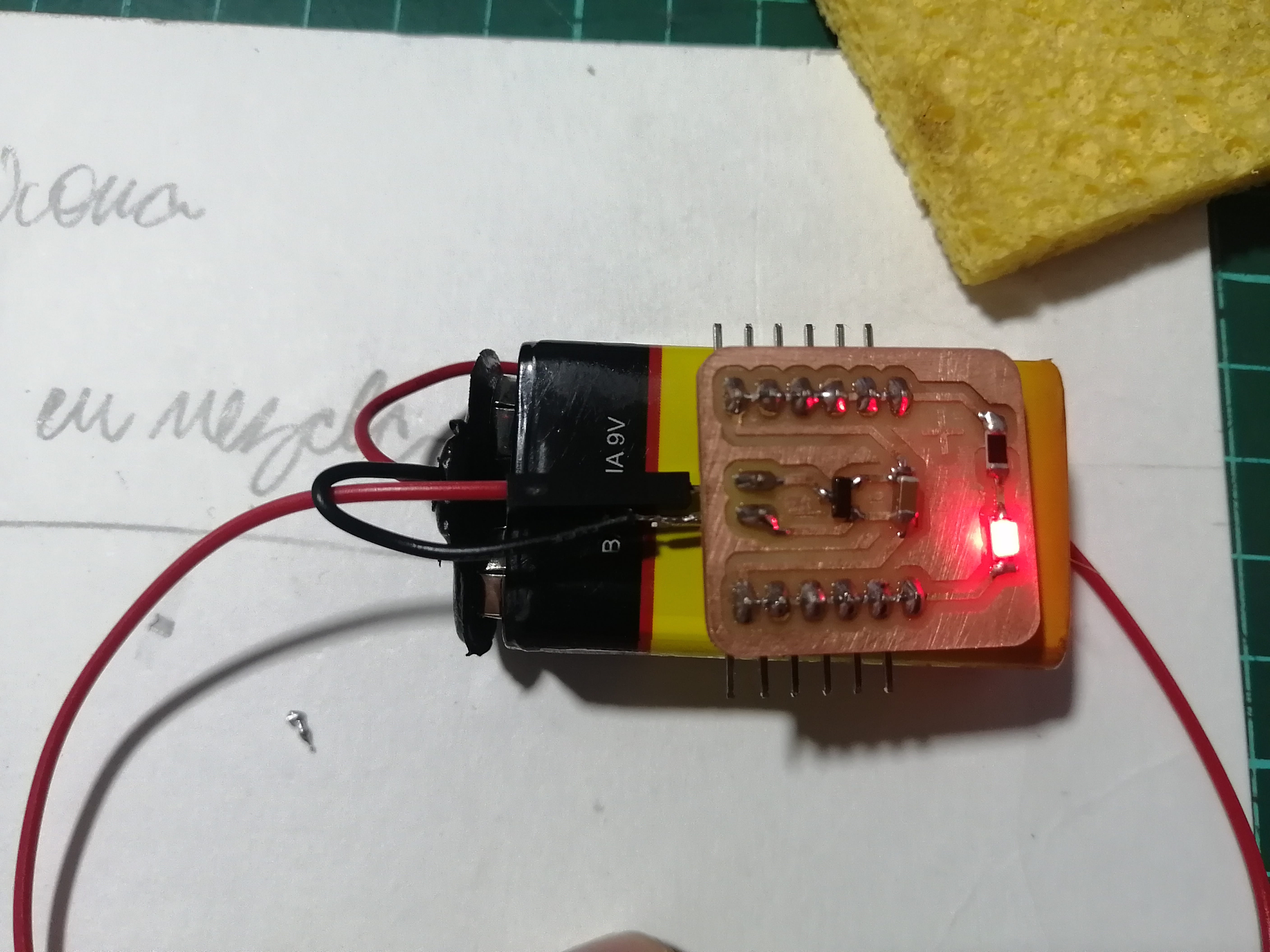
I decided to add another board to manage the power to the Octoduino, sensor, servo, and Neopixel, this power board is small enough to fit over the 9V battery and converts the power to 5V.
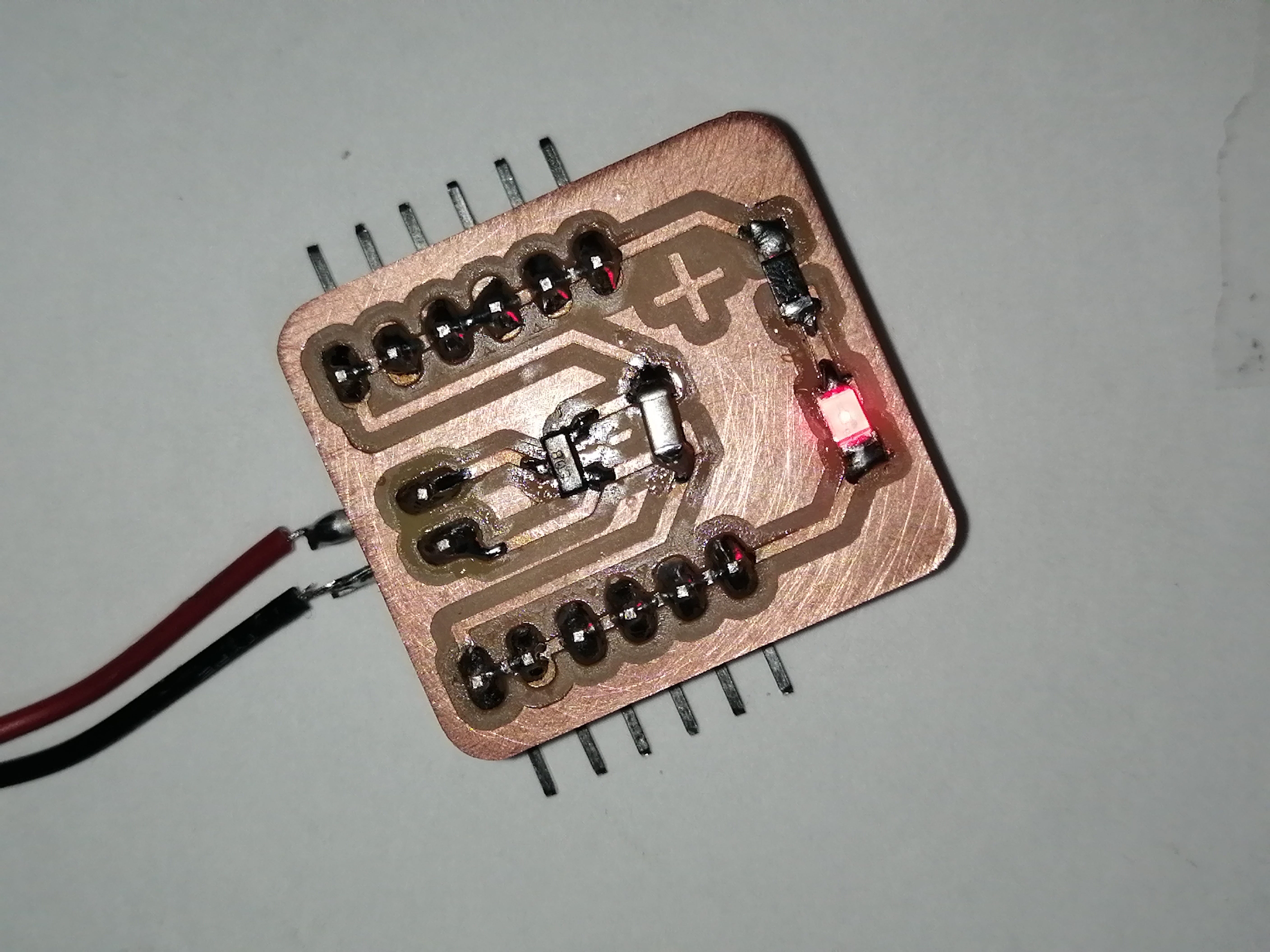
Here you can see the size, I’m not sure yet if I’ll use pins or directly solder the sensor and actuator cables to make more room.
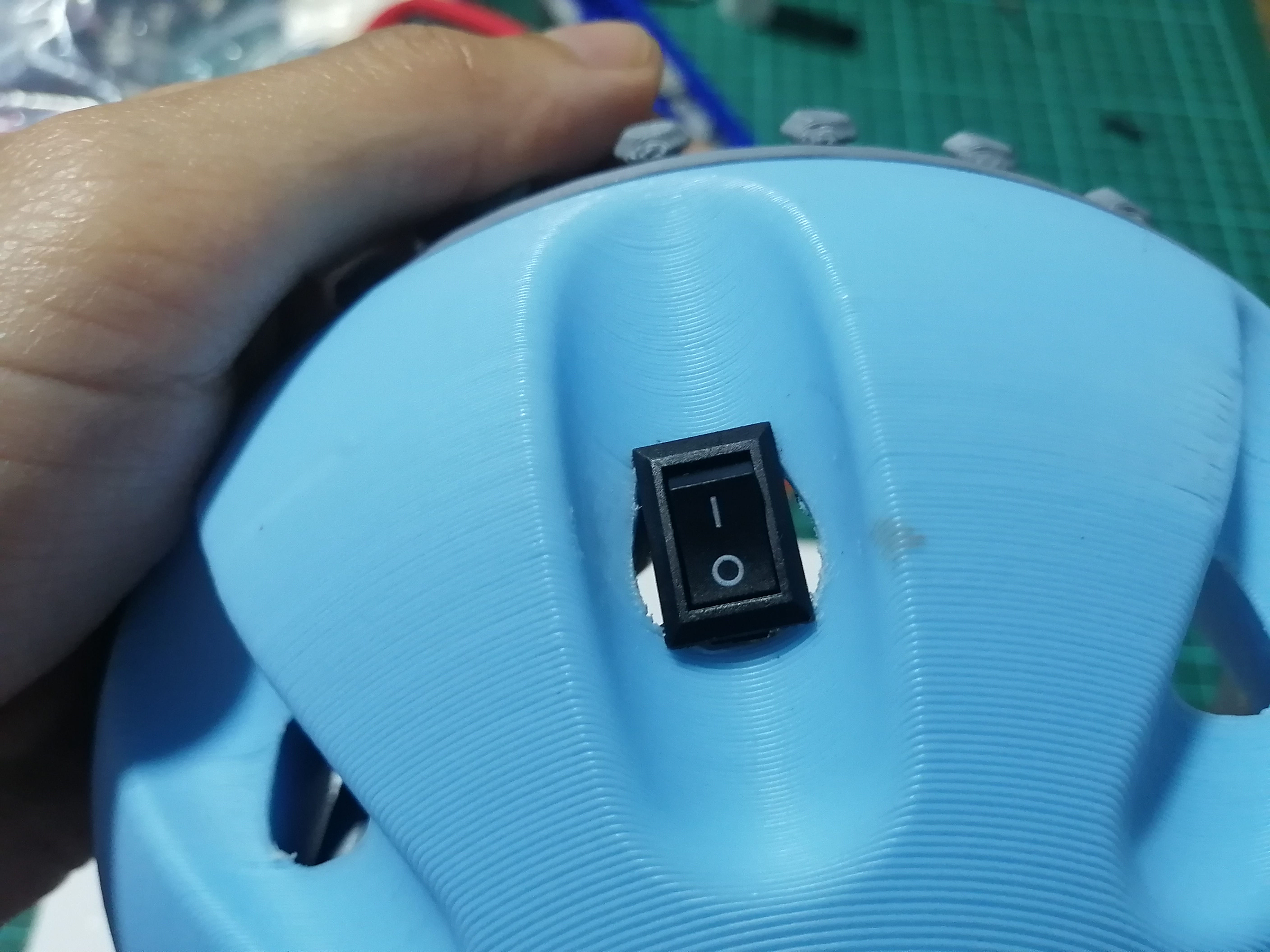
I also added a switch to turn on the device, this switch is positioned like the sensor but in the opposite direction. I only have in hand a rectangular switch small enough to fit into the hole, but a circular switch would have looked better.
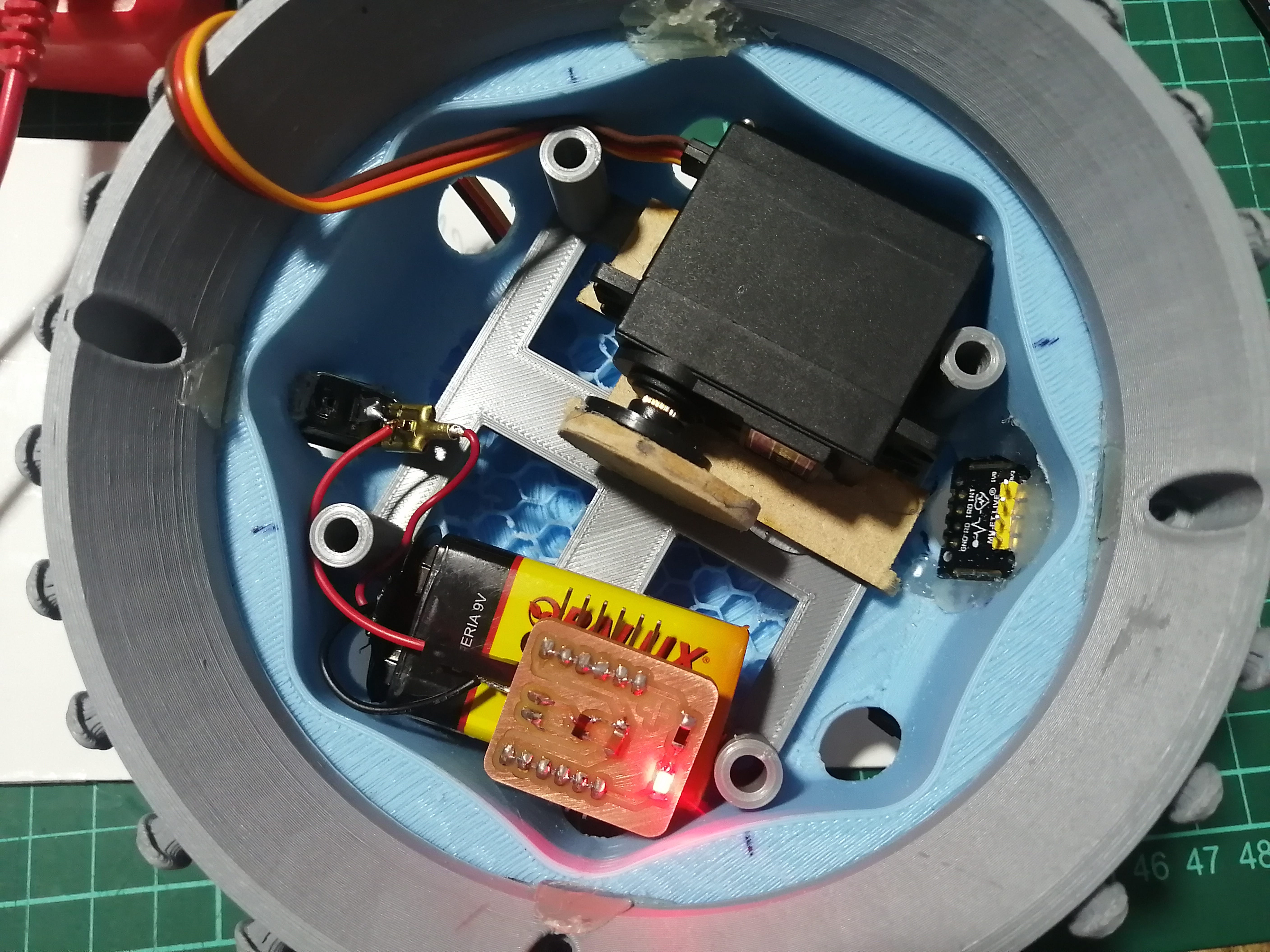
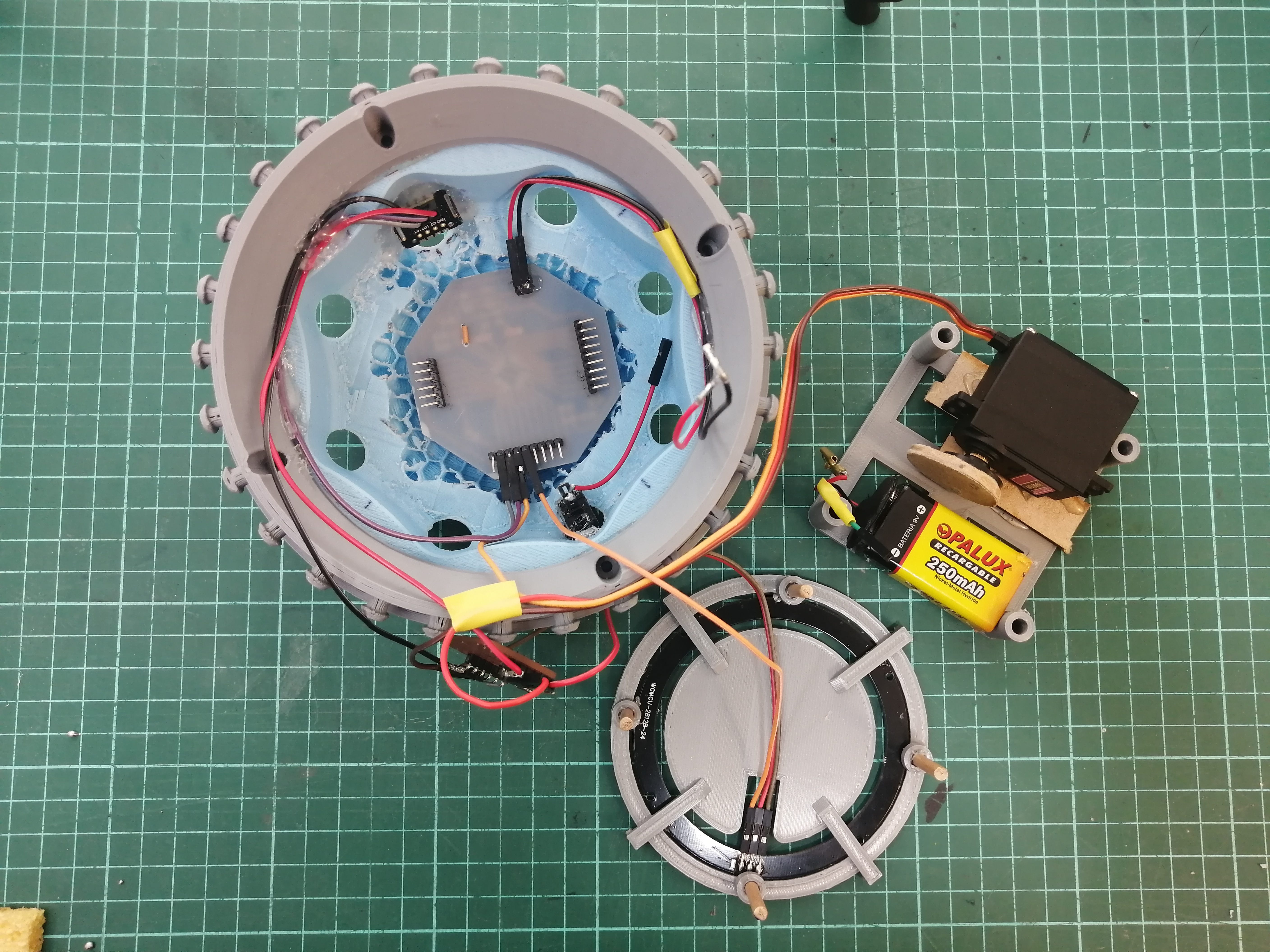
The position inside the base should go something like this, here you can see almost all the components that go under the platform and the power wiring. Notice that the position of the servo is off-centered, but this is balanced as the battery is on the other end as these are the heavier components. The switch on the left and the sensor on the right make the device comfortable to hold.
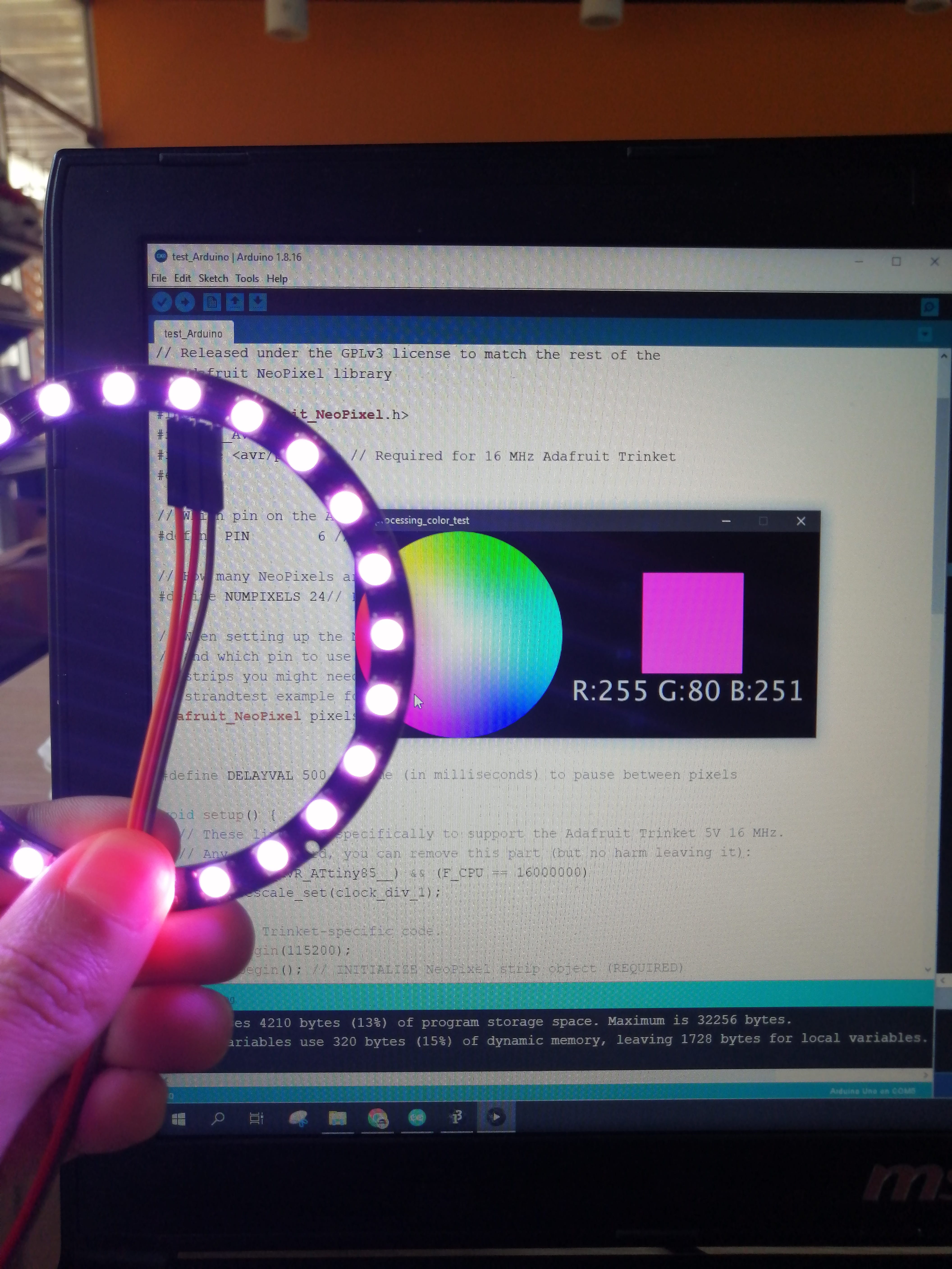
The next step is to program all the components to work together, the programming phase is already explored and tested in previous assignments like in Embedded programming week where I tested the Octoduino board and the Neopixel ring (further testing with the Neopixel ring were made in the Application programming week), also in Input devices week where I tested the Pulse sensor, and finally in Output devices week where I tested the Servo.
The programming is mostly based on Example sketches available with the libraries, and the chunks edited and combined will form the final program. I created a Flowchart of actions to make sure the programming will work as planned.
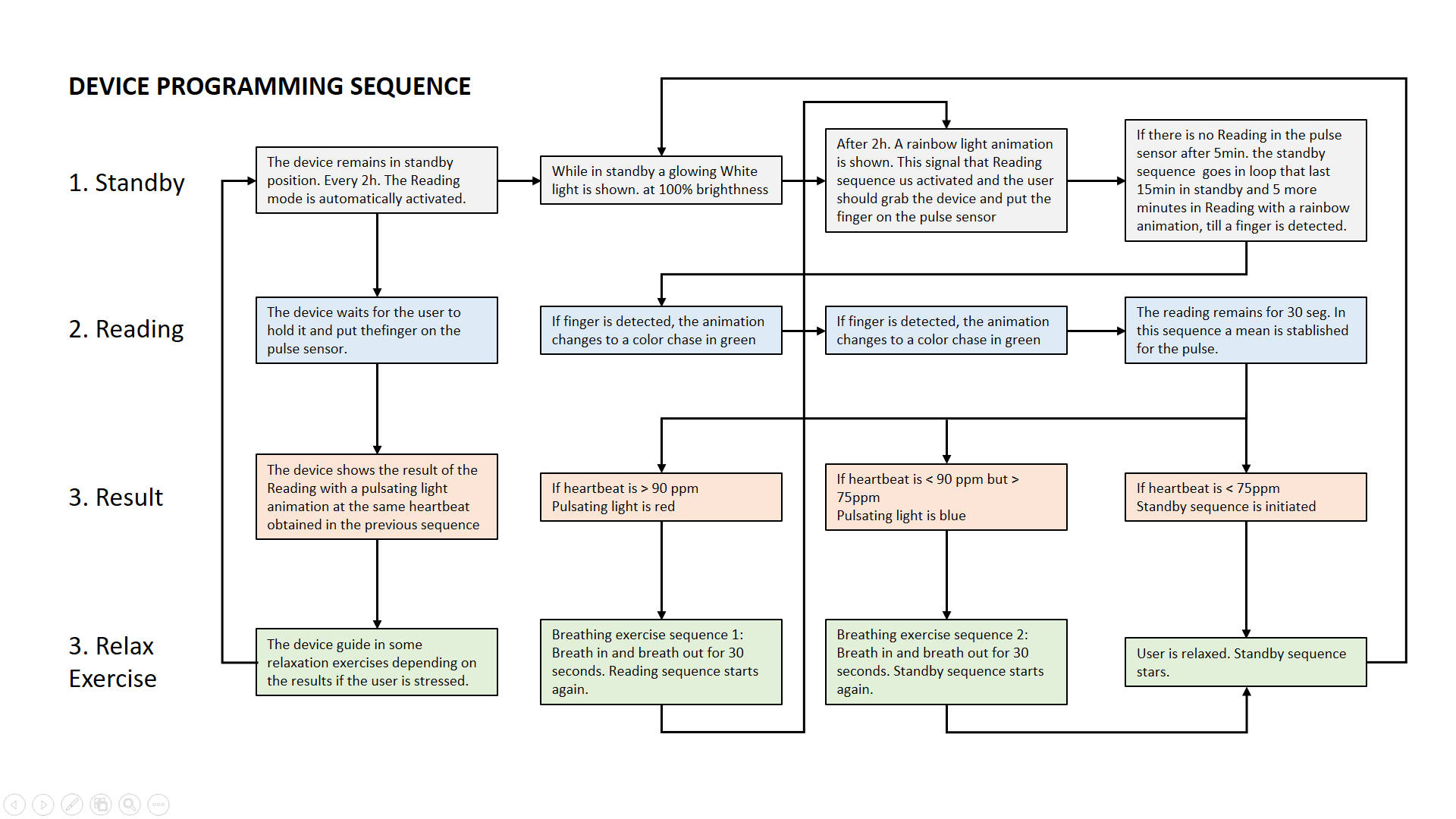
The programming sequence
Standby: The device remains in the standby position. Every 2 hours the Reading mode is automatically activated. After 2h. While on standby a glowing White light is shown. at 100% brightness.
A rainbow light animation is shown. This signal that the Reading sequence is activated and the user should grab the device and put the finger on the pulse sensor.
If there is no Reading in the pulse sensor after 5min. the standby sequence goes in a loop that lasts 15min in standby and 5 more minutes in Reading with a rainbow animation, till a finger is detected.
Reading: The device waits for the user to hold it and put the finger on the pulse sensor. If a finger is detected, the animation changes to a color chase in green.
The reading remains for 30 seg. In this sequence, a mean is established for the pulse.
Result: The device shows the result of the Reading with a pulsating light animation at the same heartbeat obtained in the previous sequence. depending on the heart rate different actions are initiated and light colors are displayed in the next stage.
Relax exercises: The device guide some relaxation exercises depending on the results if the user is stressed.
If the heartbeat is > 90 ppm a pulsating light is shown in red, followed by Breathing exercise sequence 1: Breathe in and breathe out for 30 seconds. The reading sequence starts again.
If the heartbeat is < 90 ppm but > 75 ppm a pulsating light is shown in blue, followed by Breathing exercise sequence 2: Breathe in and breathe out for 30 seconds. The standby sequence starts again.
If the heartbeat is < 75 ppm the Standby sequence is initiated because the user is relaxed.
The final code is available in the Download section at the bottom of the page.
Final Assembly and test!
Assembly is quite tricky because of the wires and the position of the Octoduino, As this goes in the bottom of the base but it needs to have connections to the sensor, servo, and Neopixel.
This is the initial part of the assembly, all connected but not mounted yet. Notice that the Octoduino is positioned upside down.
The second part of the assembly is arranging all the components in the base, I need to be very careful to not make a short circuit. Notice the opposite side of the servo and battery to even the weight in the base.
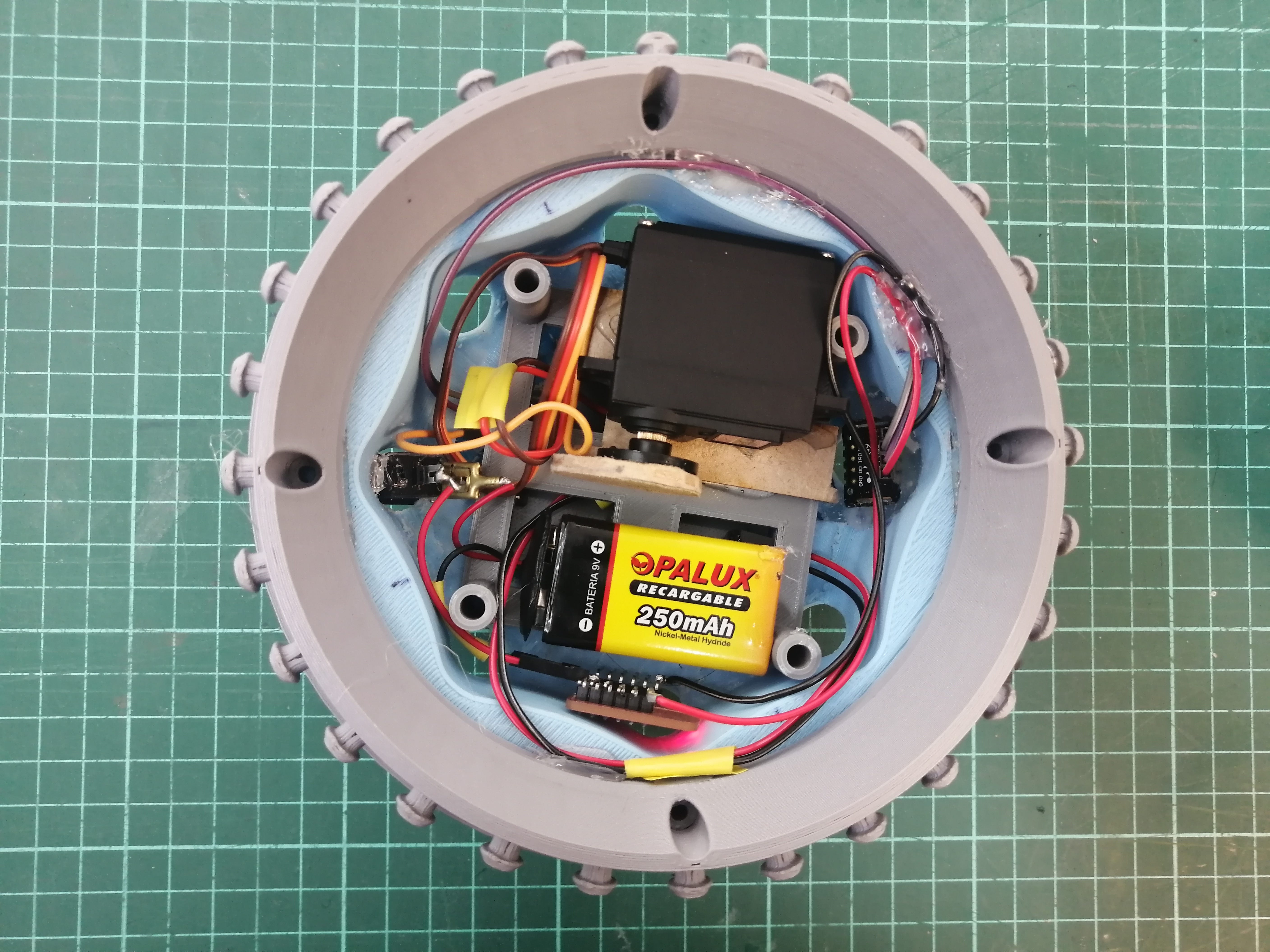
There's a little tangle, but it's necessary to connect all the components, the last step is to set up the plate that holds the Neopixel ring.
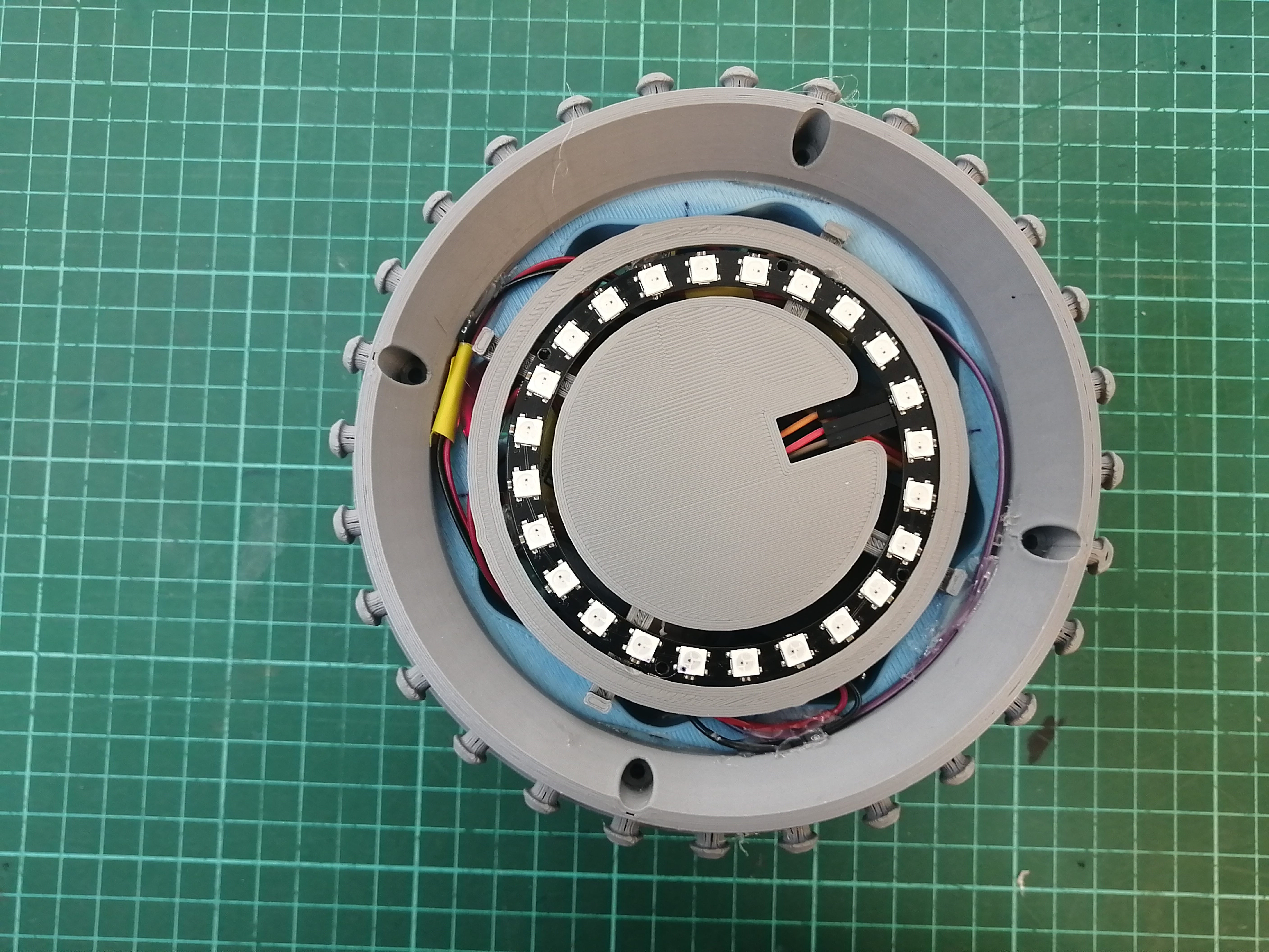
Next, comes the skin and diffuser montage, I figured out a way to make the skin close like a sleeve, place the tip, and then wrap it around the diffuser. You can see this process better in the Final video.
Stuffing the diffuser
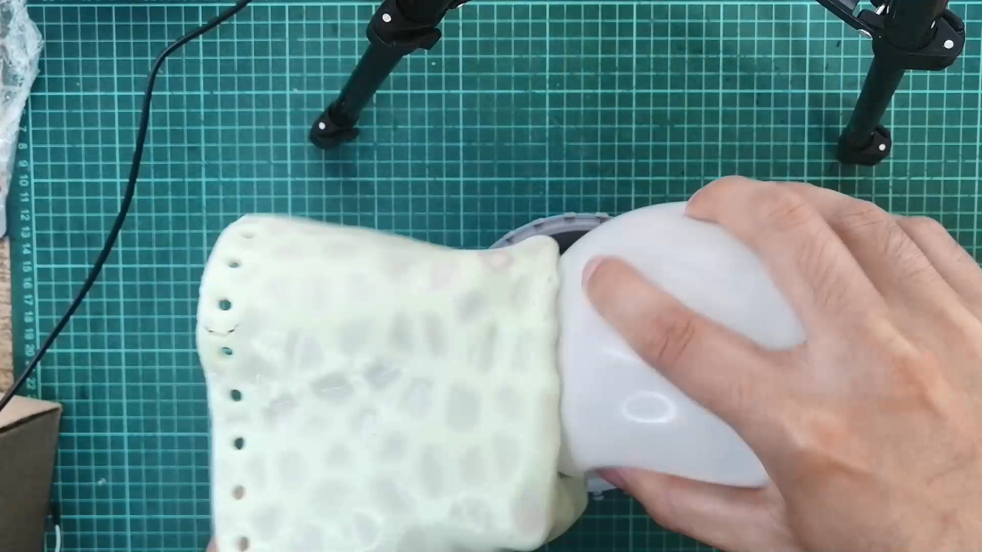
And finally, make the holes fit the buttons on the base ring. The final result is a very squishable lamp.
Some of the tests were the light in standby mode and in reading mode. this includes the reaction to a stress measure.
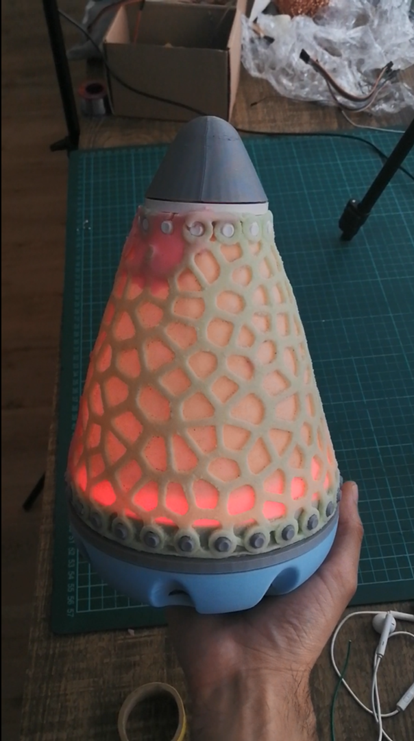
The complete sequence can be seen in the video at the top of this page, and that's all for FabAcademy 2022! 🙌
Licensing
This is the Creative Commons Attribution-ShareAlike 4.0 International License created for the Office Mood Lamp

Office Mood Lamp by Luis M. Rodriguez is licensed under a Creative Commons Attribution-ShareAlike 4.0 International License.
Based on a work at http://fabacademy.org/2020/labs/esan/students/luis-rodriguez/projects/final-project/
Downloads
3D Models
Download the grasshopper definition of the Voronoi skin here
To download the 3D files, click the download icon (top-right corner) in the viewer, this will redirect to Sketchfab and let you choose the file format to download (by default is .stl).
Another option is to click view on Sketchfab blue icon (bottom-left corner) and then select the download 3D model option from the website.
Base
Tip
Base Ring
Top Ring
Skin
Electronic boards
Download the Octoduino Board
Download the Power board
Code (.ino)
Download the Code (.ino) code for the device