Some of these issues are answered in the Final Project documentation as I developed the different components during the course, from design to mechanism to electronics. here’s a resume of the final development of the last week of the FabAcademy.
What tasks have been completed, and what tasks remain?
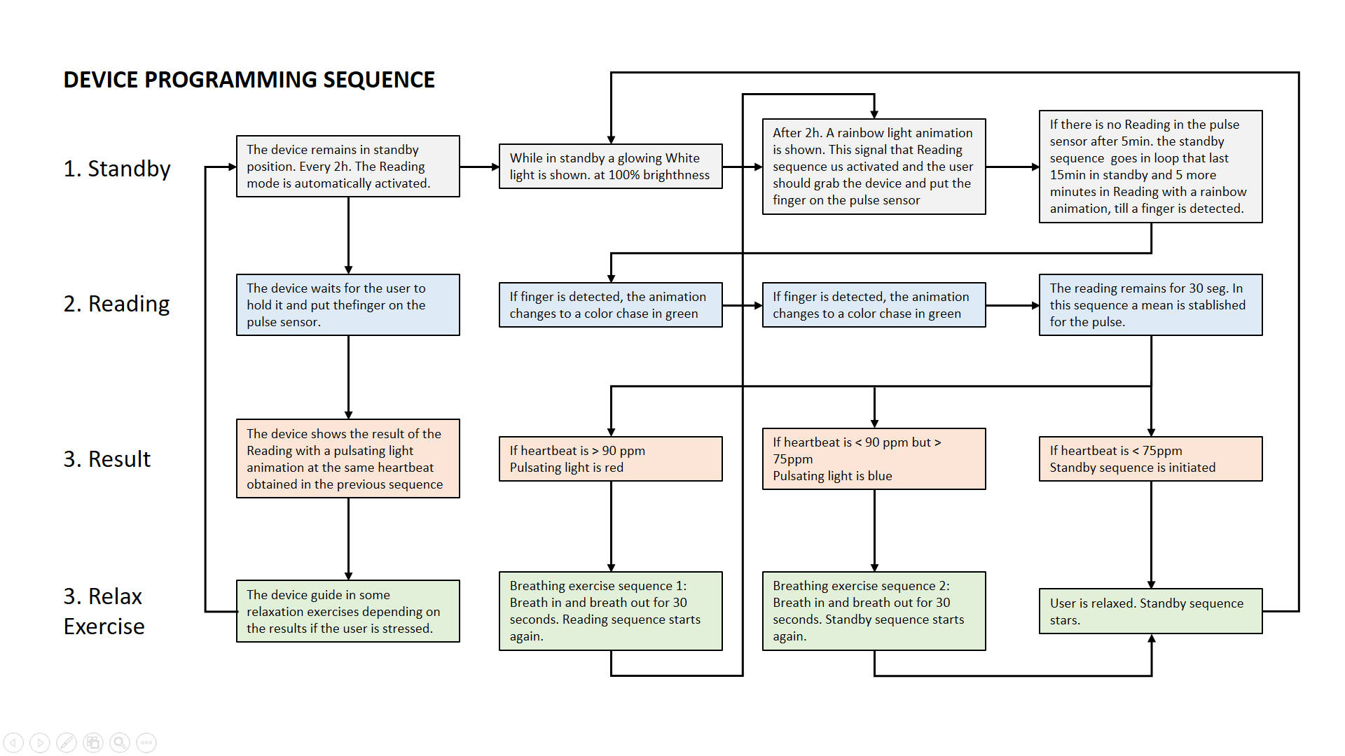
The overall design of the project, the actuation mechanism, and the electronics including input and output are completed, but there are several aspects that could be further improved. I think of the device as a first prototype.The Programming is still pending, I managed to do some tests of the sequence, but not yet a fully working algorithm, I’ll be working on it soon!
Here is a flowchart sequence of the algorithm planned:
What has worked? what hasn’t?
I find this question easier to answer as a checklistWorked
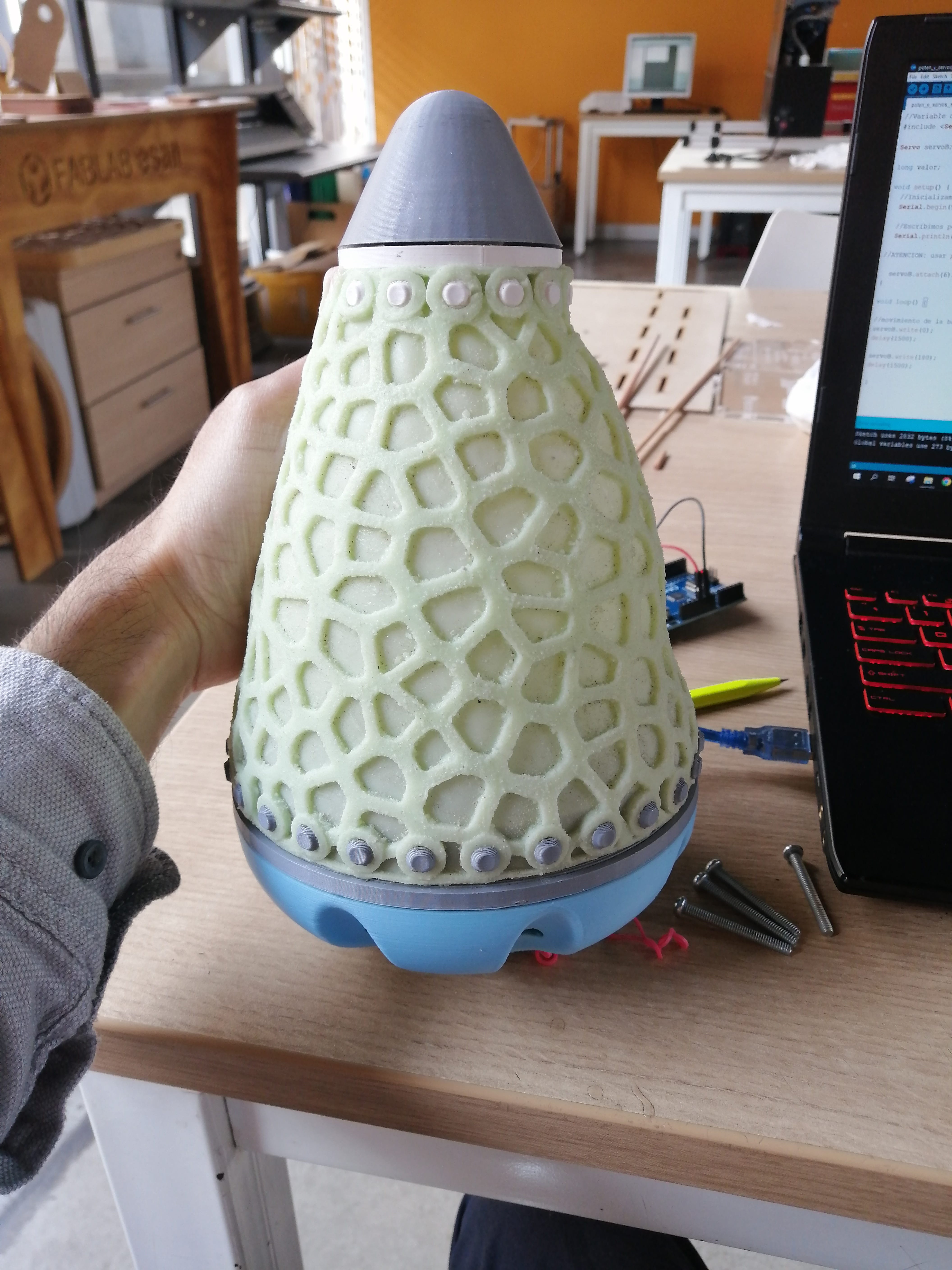
The overall aspect of the project and components. The outputs, meaning the pulsating mechanism (not as powerful as expected, but one can feel the movement) and the Neopixel light. The input is the pulse sensor embedded in the base of the lamp (not as comfortable as planned, but the readings are accurate).
The silicone stretchable skin looks and feels good, but I need to work on the closure of the back to make better pressure of the balloon diffuser.
The base and the tip made of 3D printing parts work pretty well, but it might look better if these parts were CNC milled from solid wood.
Not so much…
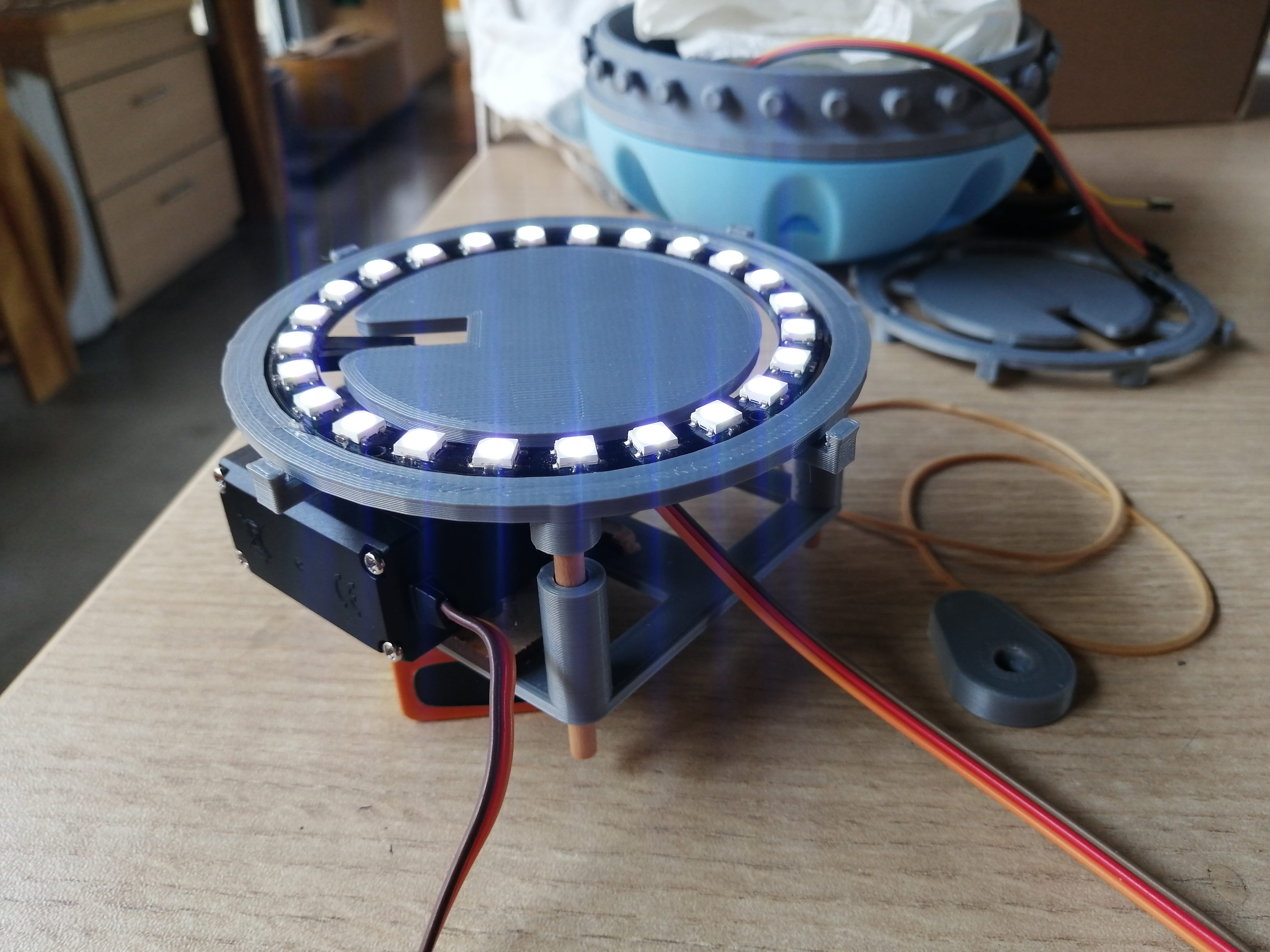
The integration of electronics is not very elegant. Where the electronic components go is defined but not resolved in an efficient way. This is especially important because the device needs to swing and be in balance, this proves complicated trying to fit in the base: the microcontroller board, the servo, the sensor, and the Neopixel ring. There’s also the mechanical component for the pulsating movement, and the diffuser (white ballon).
To get a better integration I need to get more room for the mechanism, maybe work with a smaller servo, and redesign the electronics to make my board smaller.
I originally planned that a LiPo battery would power the device, but it will now work with a 9V battery, which will help to balance the servo weight in the base better.
I Forgot to add a power switch, so I’ll adapt one hole in the base to mount a switch to turn on the device.
What questions need to be resolved?
The device needs to be user tested to know if it's practical and easy to use. This will remain unanswered till a second prototype is suitable as a user interface is made with sturdy materials!
There’s also research in user interface pending to further develop the design, I hope to present this in a paper at the FabConference next year. (2023)
What will happen when?
If the users' test and the research go as planned, I hope to have a viable product to measure and mitigate stress in the work environment. There are a lot of possibilities to improve the device, like wearable integration and swarm capabilities to track stress measures in groups. Some of these are addressed in the Invention, intellectual property, and income assignment.
What have you learned?
The most valuable lesson learned is to test fast and adapt, this often requires skills beyond digital fabrication. I am happy with the result and will develop the device further using the dissemination plan set in previous assignments.
Collaboration is important to get new ideas and improve, so BIG thanks to the FabLab ESAN Team and fellow FabAcademy students!
What does it do?
A desktop device (lamp) to place on the office desk to monitor stress levels in the office environment.
This will work by reading the biologicals signs of stress (in his case heart rate) of an employee and displaying it in color code (ex.: blue for relaxed gradually turning red if stressed); allowing them to be conscious about increasing stress levels during the day and the need for taking a short break or as a reminder of taking an active break. ;)
The device will also help manage or reduce stress by making the office worker engage in respiration exercises through pulsating movements (inflate and deflate) to synchronize with the user state by guiding the breathing.
Who’s done what beforehand?
On the technical aspect, stress measurement using a pulse sensor is widely used in smartwatches and other health devices that incorporated this feature and measurements by health monitoring apps.
Some examples from FabAcademy projects:
Some other investigations/projects:
What did you design?
The device is in itself a tangible user interface (TAU), I designed the shape of the device consisting of a 3 piece body (base, middle, and tip) with different functions and its assembly, the electronic board to control the sensors, the communication between the sensor (pulse reader), actuator (servo) and display the information on lights (Neopixel), also designed the mechanism for the pulsating movement including a flexible outer skin.
What materials and components were used?
Materials:
Base: It was first planned as MDF or fancy solid wood as it needs to be heavier for the rolly-polly effect. The final prototype ended up being 3D printing the base, which also functions as a housing for the electronics components.
Middle: This is the part that will have the pulsating effect, this flexible soft skin is cast in silicone from a 3D Printed Mold.
Tip: Cast clear resin. (3D printed mold).
Internal Mechanism: 3D print and laser cut MDF.
Connection pieces: Fit between parts by 3D print o press-fit design.
Electronics: CNC milling in the Modela
Components:
- ATMega328P (I made my own board Octoduino)
- Pulse-oximeter sensor
- Lithium battery 9v
- Neopixel ring
- Servo motor
- Various electronic components such as resistors, capacitors, FTDI, ISP, resonators, wires, etc.<
Where did they come from?
The materials and components came from the FabLab ESAN inventory and personal purchase. Some components were purchased from local vendors like the pulse sensor and the Neopixel ring.
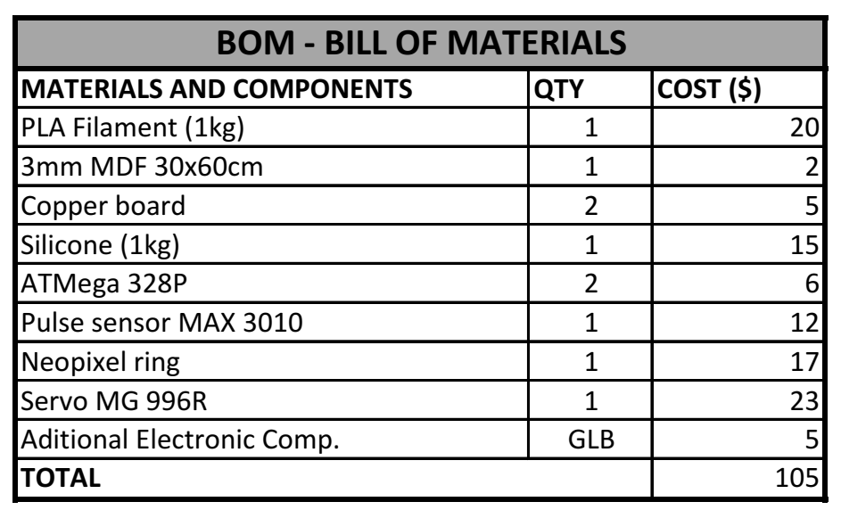
How much did they cost?
The total cost of the final project is around $100
What parts and systems were made?
All parts in the Design are designed and fabricated in the FabLab, except the pulse sensor, the neopixel ring, and the Servo.
The device is based on three modules:
Base: This piece will be the housing for the electronics components and the main support for the structure and mechanism.
Middle: This is the part that will have the pulsating effect, on the outside the flexible skin stretch and allow the light through and on the inside, it houses a pneumatic part (a ballon that doubles as a light diffuser for the Neopixel ring) and the internal mechanic and motor for the pulsating movement.
Tip: On top of the device this part will house a LED that indicates actions on color code or blinking.
The internal Mechanism will allow the pulsating movement inside the device by compressing a pneumatic part and expanding the flexible skin.
What processes were used?
- CNC machining
- 3D printing
- Laser cutting
- Molding and casting
- Design, milling, and soldering of the electronic board
- Vinyl cutting
What questions were answered?
Will it look and feel good? It does, one of the initial concerns was that as having many parts and different fabrication techniques the final device may look a bit Frankenstein-ish. But It ended up looking very true to the original digital design.
Will the components fit? They fit, but very tightly, the egg shape of the device gives some space constraints for the electronic components and the mechanism that needs to fit inside the base pocket.
Will it balance correctly? It does, but it needs a little fine-tuning. The device should tumble like a rolly-polly, so the balance of the weight is crucial. This was made by making the base heavier, but at the same time with enough space for housing the components, so the size of the pocket carved in the base is considered carefully. The weight distribution is achieved by carefully placing the servo and the 9v battery.
Will the mechanism be stable enough or have enough compression to make the pulsating movement? The mechanism does work, but as having a strong constraint in the space available the movement is not as dramatic as planned, it is very subtle and difficult to show on video, but is very perceptible at the touch.
What about the gear ratio to mimic the respiration cycle? As mentioned before space and weight needs to be carefully considered, to achieve smooth movement the type and control of the motor fine-tuning are needed.
Will the readings and communication be accurate? Yes, the readings are accurate. but getting consistent measurements of the pulse sensor (even when it is working on its own) is tricky, To have consistent measurements I made a sort of housing to place the finger comfortably and it seems to go well.
Will it be noisy? One concern is that as a device to be used in calming exercises, the noise level needs to be minimum, the only sound the device emits is the servo making the pulsating movement, this is not loud at all, but is kind of annoying, a better mechanism (silent) design or actuator is needed.
What worked? what didn’t?
Check the top of this page for a brief answer.
How will it be evaluated?
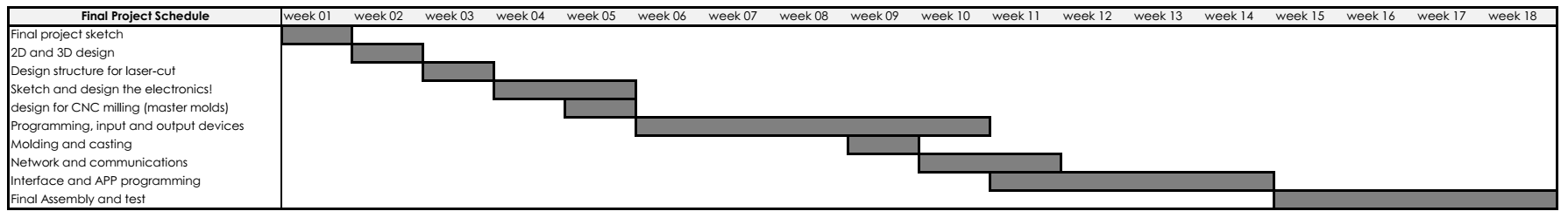
The development was planned in spirals, the original planning went as follows:
First Spiral: Make the first prototype to test the fitting of the modules and test the fitting of electronic components
Second Spiral: Design and fabrication of the pulsating movement and the integration with the prototype.
Third Spiral: Programing and integration of the application with user testing!
I ended up working on more than one spiral at a time, but all of them were successfully completed!
What are the implications?
The implications are answered in the Final Project documentation as I developed the different components during the course.