In this week's assignment we need to:
-
Read the datasheet for the microcontroller you are programming
-
Program the board you have made to do something, with as many different programming languages and programming environments as possible.
New board: ATMEGA328P
The board I made in Electronics design week got lost during the lockdown, so I need to create a new one, this time using an ATMEGA328P instead of the classic ATtiny44. This board is based on the SatshaKit design developed by Daniele Ingrassia.
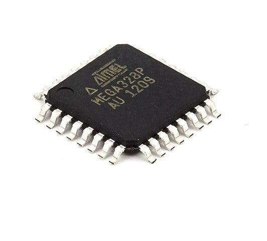
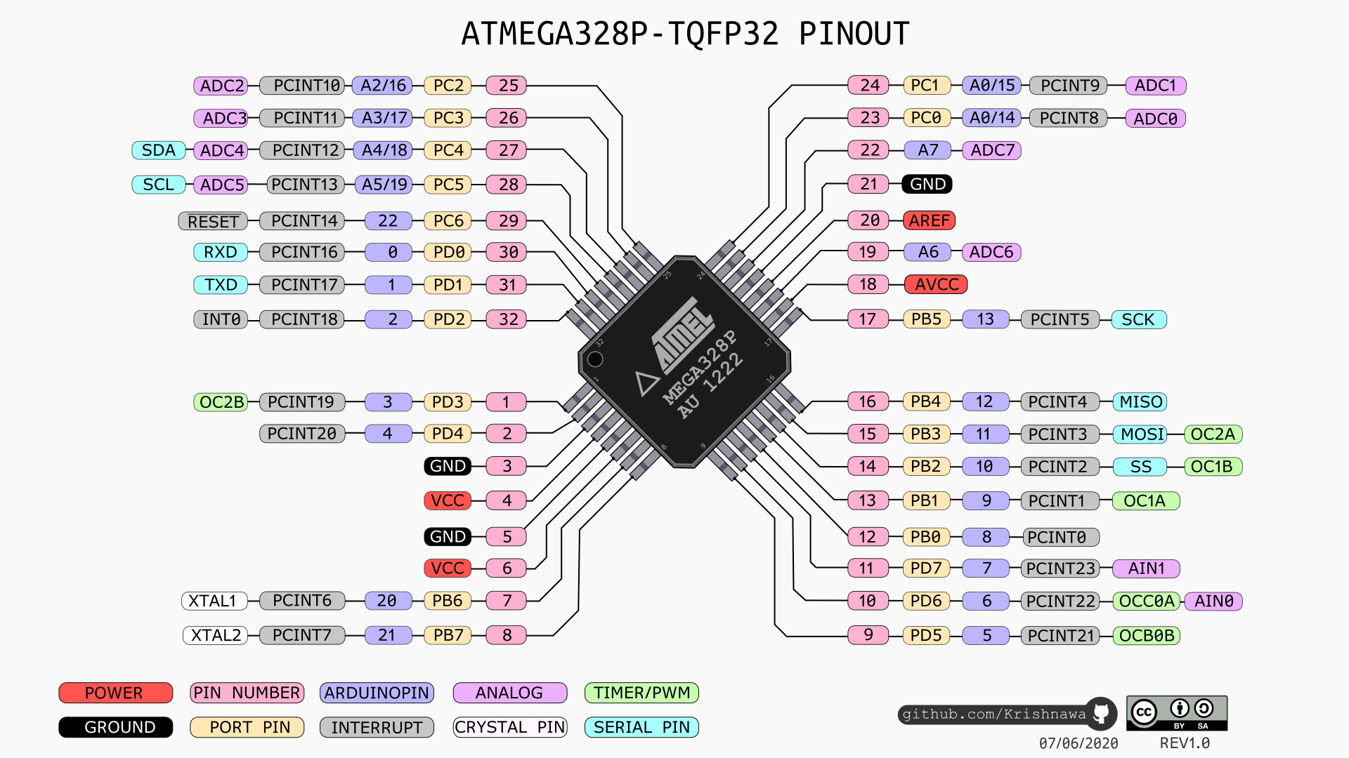
The ATMEGA328P Datasheet and Pinout, the pinout is very important as it shows the PIN and its corresponding Arduino pin for programming.
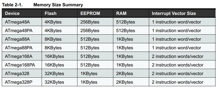
The ATMEGA328P datasheet is around 650 pages and works for several ATMega microcontrollers, according to the Datasheet comparing the processors the 328P has more EEPROM and RAM available.

Memory size comparison.
This board has a special design to fit inside my final project and is called the Octoduino. I’ll be using this new board for the input and output assignments.
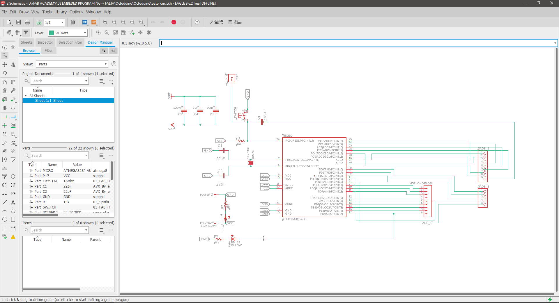
The design uses the maximum pins available in the ATMEGA328P to have easy connections.
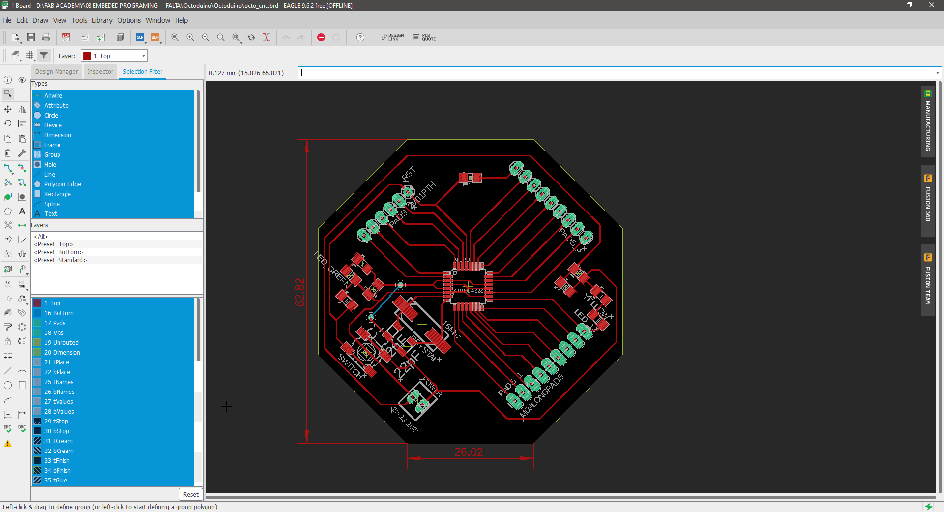
This is the board without the stuffing.

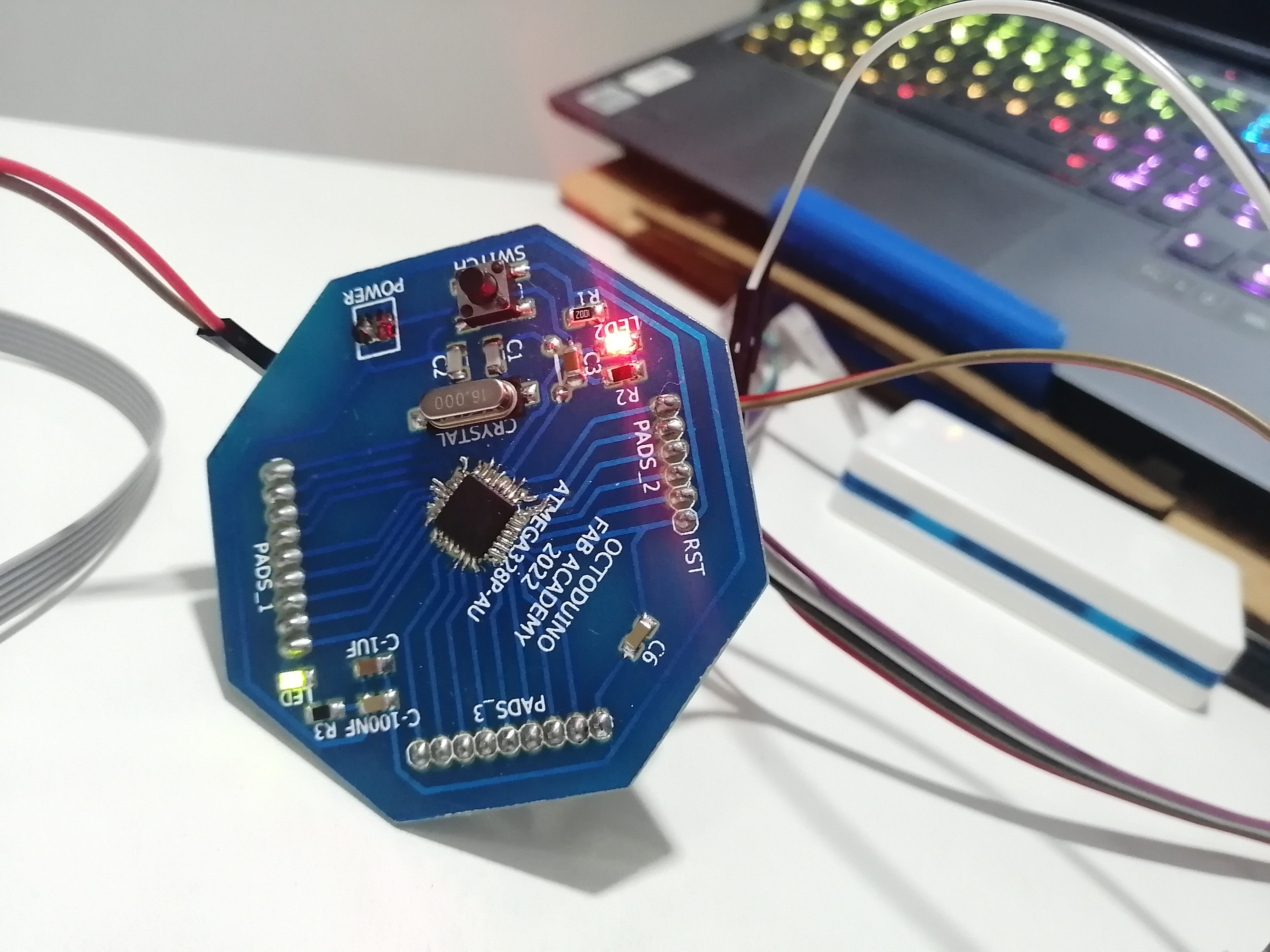
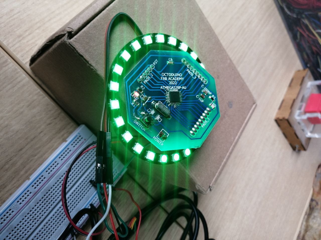
And this is the final result with the components soldered and working, and just like that the Octoduino is born!
Programming the Octoduino
The Octoduino uses the same microcontroller as the Arduino Uno, because of this I’ll be using the Arduino IDE to test the programming.
I’ll be using the previously made FabISP in Electronics production week as a programmer.
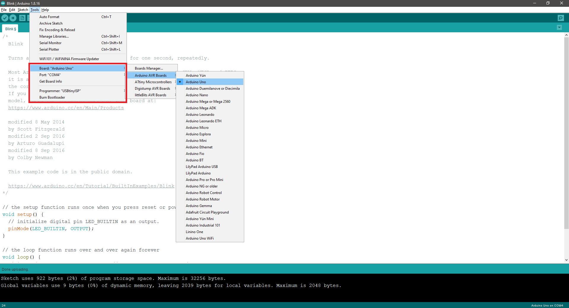
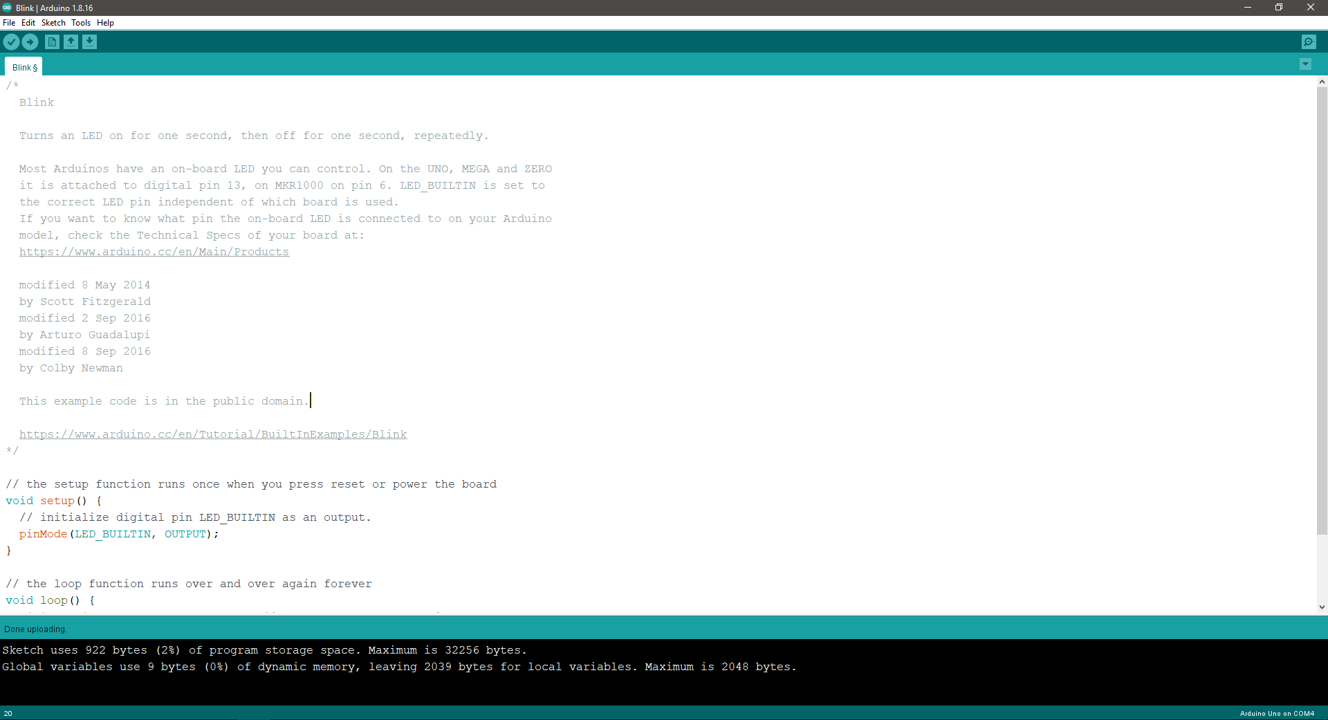
It is important to choose the correct settings in the Arduino IDE, such as the Board must be Arduino UNO, and the Programmer must be set to USBtinyISP.

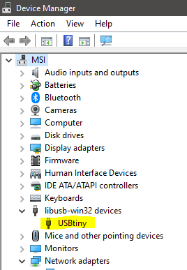
To get the FabISP to work with a windows OS a driver must be installed, I tried several, but the one that works is an Adafruit driver. Once it's correctly installed and plugged it will be shown as USBTiny in the device manager.
To set the ISP as Programmer I connected the ISP pins to the corresponding pins in the Octoduino, I used the Datasheet and the pinout diagram to connect the header to the Octoduino 15 to 17 pins.
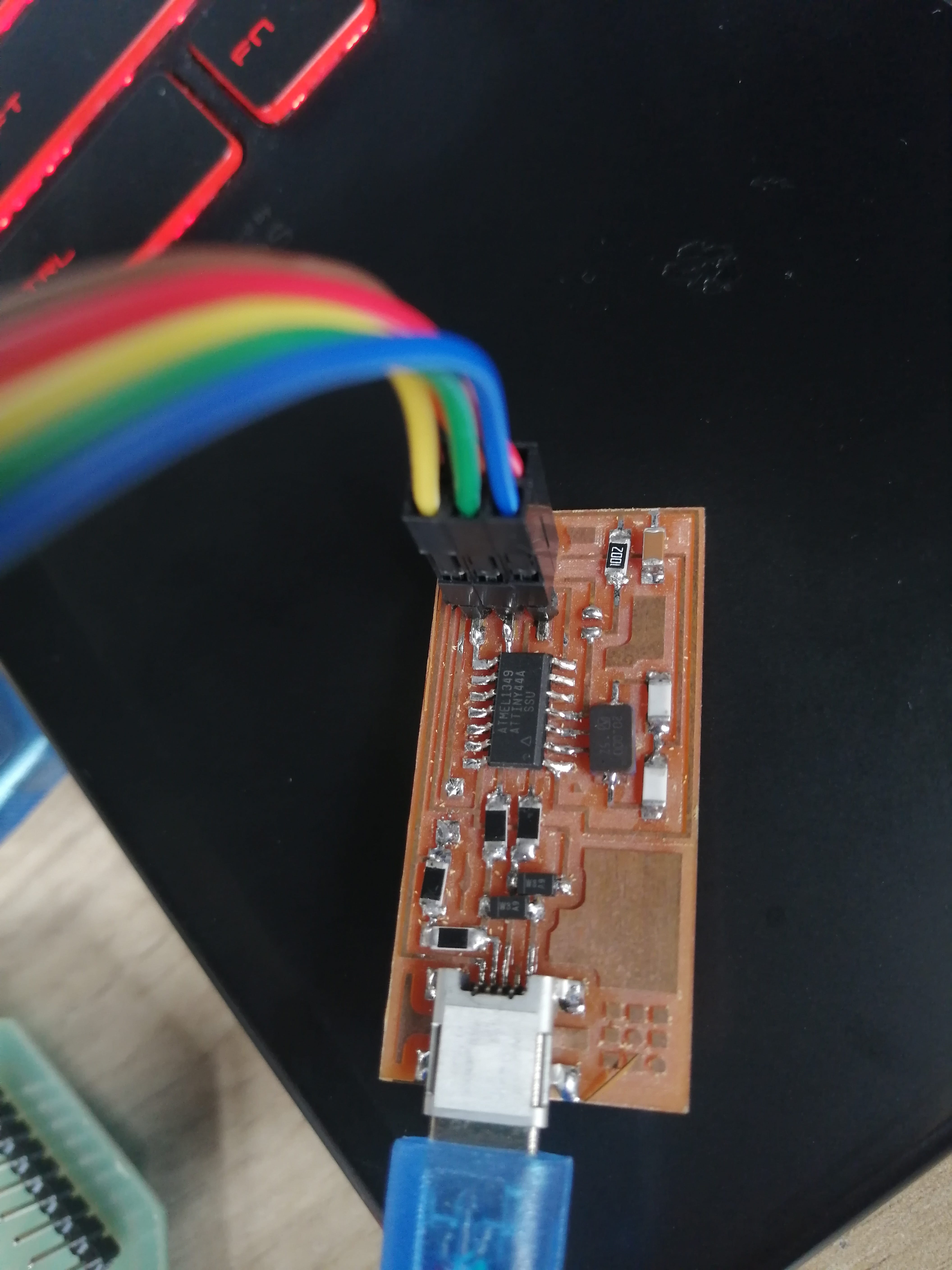
I'm also using a USB-FTDI cable to power up the Octoduino.

To test all the connections I uploaded a basic blink code that is an Arduino example. The upload went alright and the LED on the Octoduino (pin 17) turned on according to the code, I modified the blinking speed to 100ms and uploaded the code to test everything was working fine.
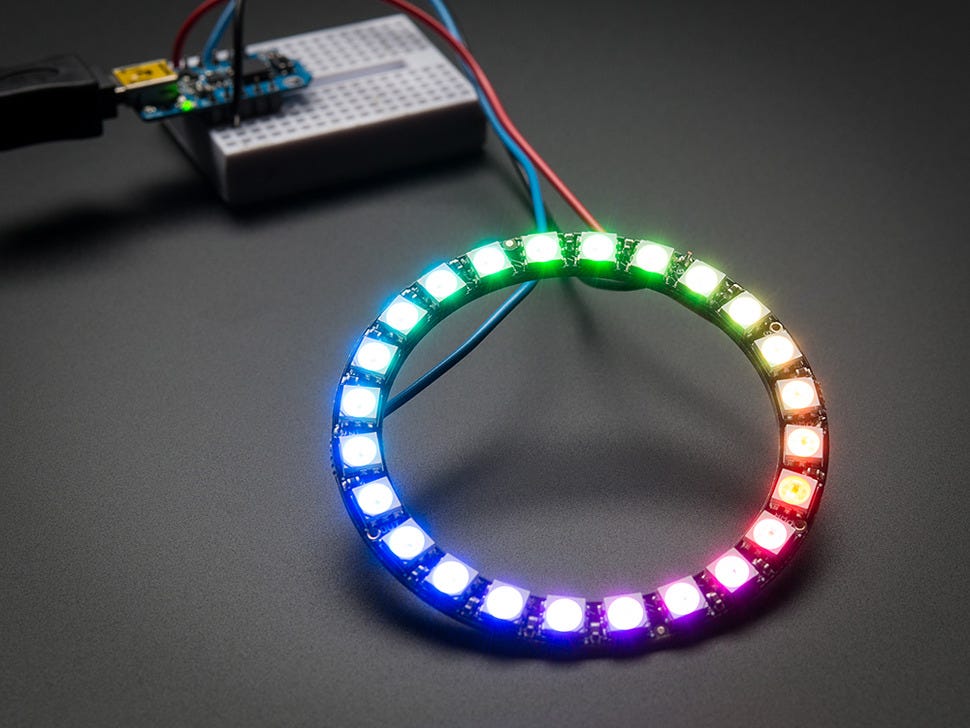
Later I decided I could program a simple animation using a neopixel ring, to test if this could be used later in my final project as light indicator.
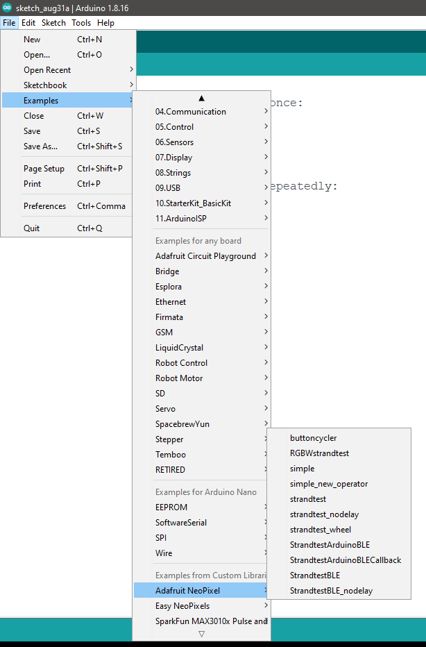
For this I need to upload the Neopixel Library for Arduino from Adafruit. As is mentioned on the library page: Controlling NeoPixels “from scratch” is quite a challenge, so we provide a library letting you focus on the fun and interesting bits.
There are two methods for installing the libraries, one is to install it directly from Arduino IDE, under the tab Sketch / Include library / Manage libraries. Then search for Neopixel strip using the search bar.

Once the library is installed we can access some code examples to control the neopixel.
I Begin to edit the code named Simple, to make a counter like animation, that lights a pixel every second until the ring is completed. The code works by defining a PIN to send the signal for the Neopixels (in this case the Arduino pin is 6, and the corresponding Octoduino pin is 16). The second parameter is NUMPIXELS that is set to 24, because that's the number of pixels on the ring.
In the Void Setup is necessary to initialize the neopixels with the command pixels.begin();
In the Void Loop there are three commands:
pixels.clear(); to set all pixel colors to ‘off’
for(int i=0; i<NUMPIXELS; i++)
The counter to light the pixels one after the other
pixels.setPixelColor(i, pixels.Color(0, 255, 0));
In this case we are turning only the pixels in color green.
pixels.show();
To send actually light the pixels
The final edited code looks like this:
// NeoPixel Ring simple sketch (c) 2013 Shae Erisson
// Released under the GPLv3 license to match the rest of the
// Adafruit NeoPixel library
// Edited by Luis M. Rodriguez for FabAcademy 2022

#include < Adafruit_NeoPixel.h>

// Which pin on the Arduino is connected to the NeoPixels
#define PIN 6

// How many NeoPixels on the ring
#define NUMPIXELS 24

// When setting up the NeoPixel library, we tell it how many pixels,
// and which pin to use to send signals.

Adafruit_NeoPixel pixels(NUMPIXELS, PIN, NEO_GRB + NEO_KHZ800);

#define DELAYVAL 1000 // Time (in milliseconds) to pause between pixels

void setup() {

  pixels.begin(); // INITIALIZE NeoPixel strip object (REQUIRED)
}

void loop() {
  pixels.clear(); // Set all pixel colors to 'off'

  // The first NeoPixel in a strand is #0, second is 1, all the way up
  // to the count of pixels minus one.
  for(int i=0; i< NUMPIXELS; i++) { // For each pixel

 // pixels.Color() takes RGB values, from 0,0,0 up to 255,255,255

 pixels.setPixelColor(i, pixels.Color(0, 255, 0));

    pixels.show();   // Send the updated pixel colors to the hardware.

    delay(DELAYVAL); // Pause before next pass through loop
  }
}
To upload the code I used the “upload using programmer” option on arduino, tested in the first steps in this assignment, then disconnected the FabISP and connected the VCC +GND + Signal (pin 16) to the neopixel ring using a breadboard, because I noticed I do not have a VCC pin directly from the Octoduino available, so I’ll be making a power board soon.
This is the final result of the counter animation on the Neopixel ring:
Electronic boards
Download the Octoduino Board used in this assignment.
Group Assignment
For the group assignment we need to:
- Compare the performance and development workflows for other architectures.
- Document your work to the group work page and reflect on your individual page what you learned.
The group development workflows are documented in my classmate's FabAcademy pageLesly Ramirez
This covers:
- RASPBERRY PI PICO Based on RISC architecture
- ARDUINO MKR1000 WIFI Based on RISC architecture
- NodeMCU ESP12E DEVKIT Based on HARDWARE Architecture