Group Assignment
Lab safety training
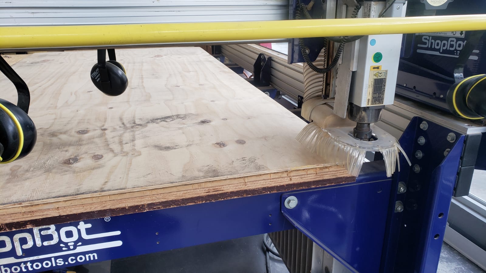
The lab safety training went online as ESAN FabLAb is still closed due to you-now-what. The video demonstration began with the instructor showing the machine and explaining the safety measures and working protocols of the ShopBot PRSalpha Machine at FabLab ESAN with a bed size of 1.52 * 2.44m.
The basic safety equipment using the shopbot includes safety goggles for eye protection because some particles could fly into your eyes and ear muffs because the thing is loud! (87dB)
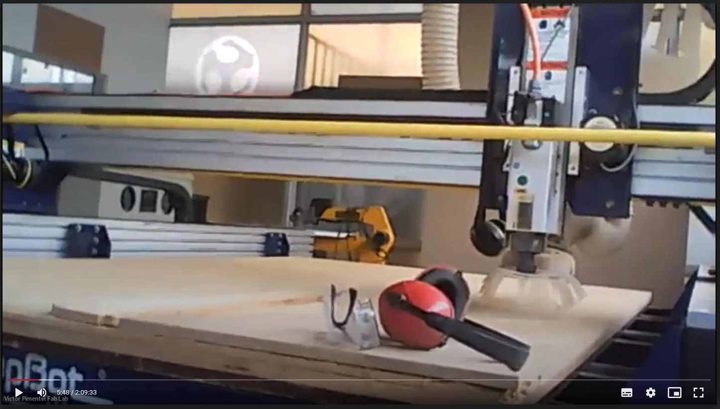
The instructor also explained the “secured line” around the machine when it's in operation and the kill switch or emergency stop of the machine.
Test
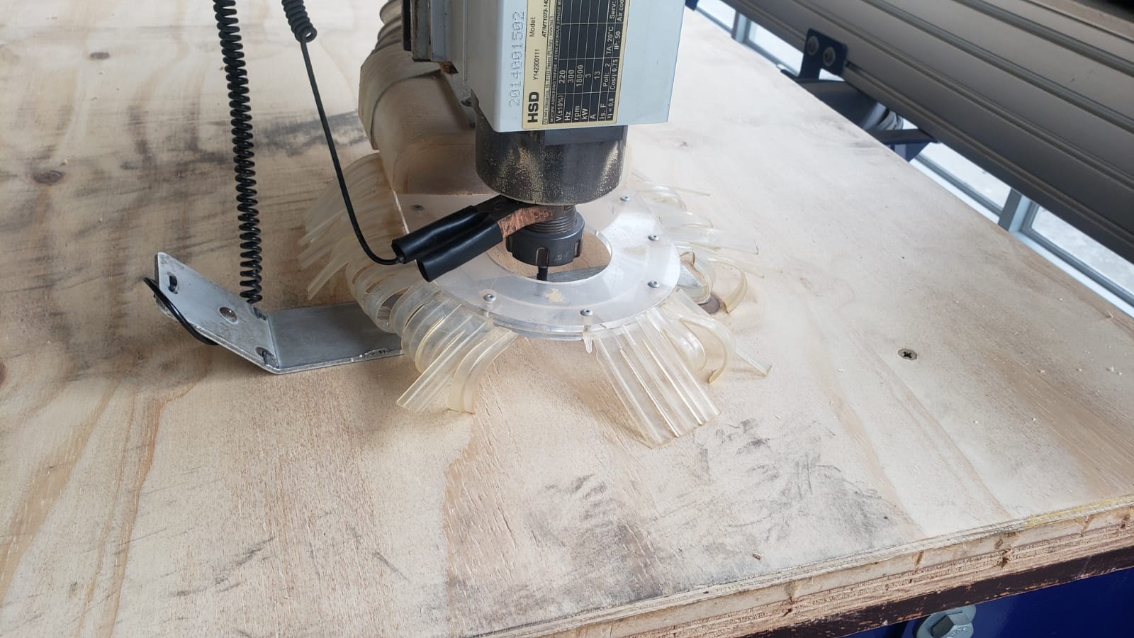
Next, the instructor explained the parts of the machine, including milling bits, collet, spindle motor, axis, and sacrificial bed. The process for setting up a new sheet for cutting and how to fix it to the bed.
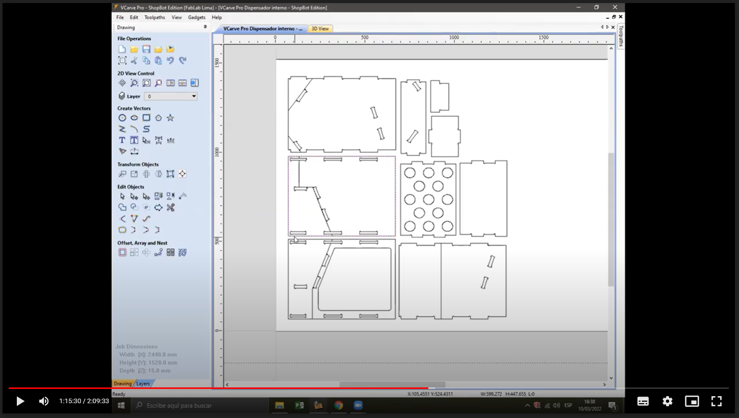
Also showed some of the most common materials for machinings like plywood and MDF and some examples of joinery like press-fir and finger joints. The demo continued with the use of software V Carve PRO and how to set the machining cuts, using in or out cut settings, setting up T bones and dog bones, etc.
Next comes the bit settings, We selected a 1/4" down cut bit and set up the + pass depth at 0.25 in, step over 0.125 in, spindle speed 14000 rpm , feed rate 3.0 in/sec, and plunge rate 1.0 in/sec.
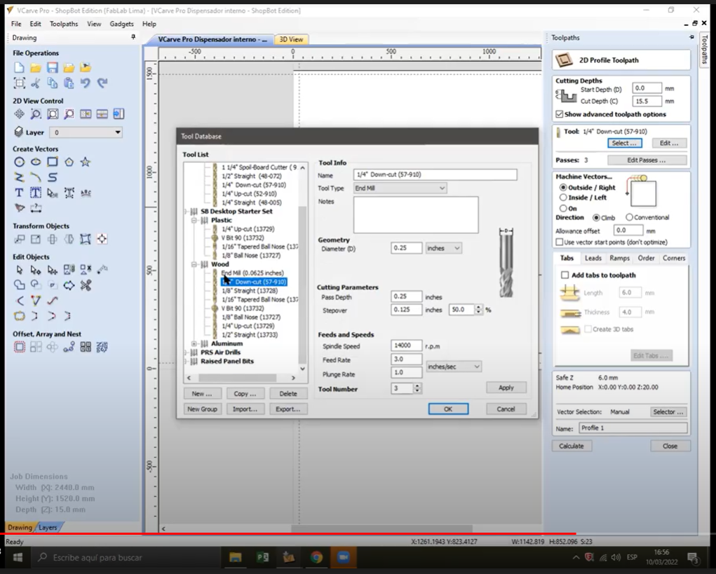
The software also has an option to preview the toolpaths, next the toolpaths are exported as a .sbp extension (G-code for shopbot)
After exporting the G-code we need to open the machine software to home all axis and set the starting point of the work.
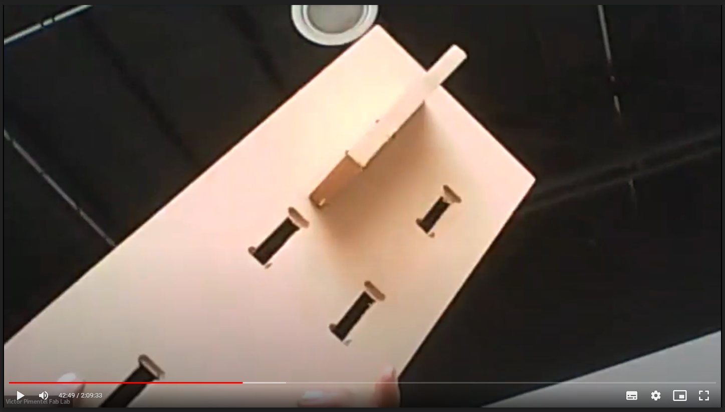
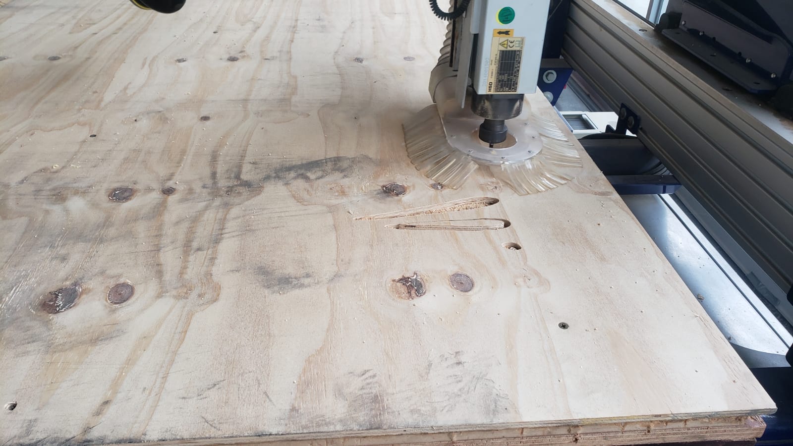
The demo ended by cutting small squared pieces of plywood and MDF to compare the accuracy and finish of the machining process. I’ll be repeating this process for my design.
Individual Assignment: Design
For this assignment, I would produce some kind of urban furniture to be tested on campus as the FabLab is located at ESAN University.
Concept
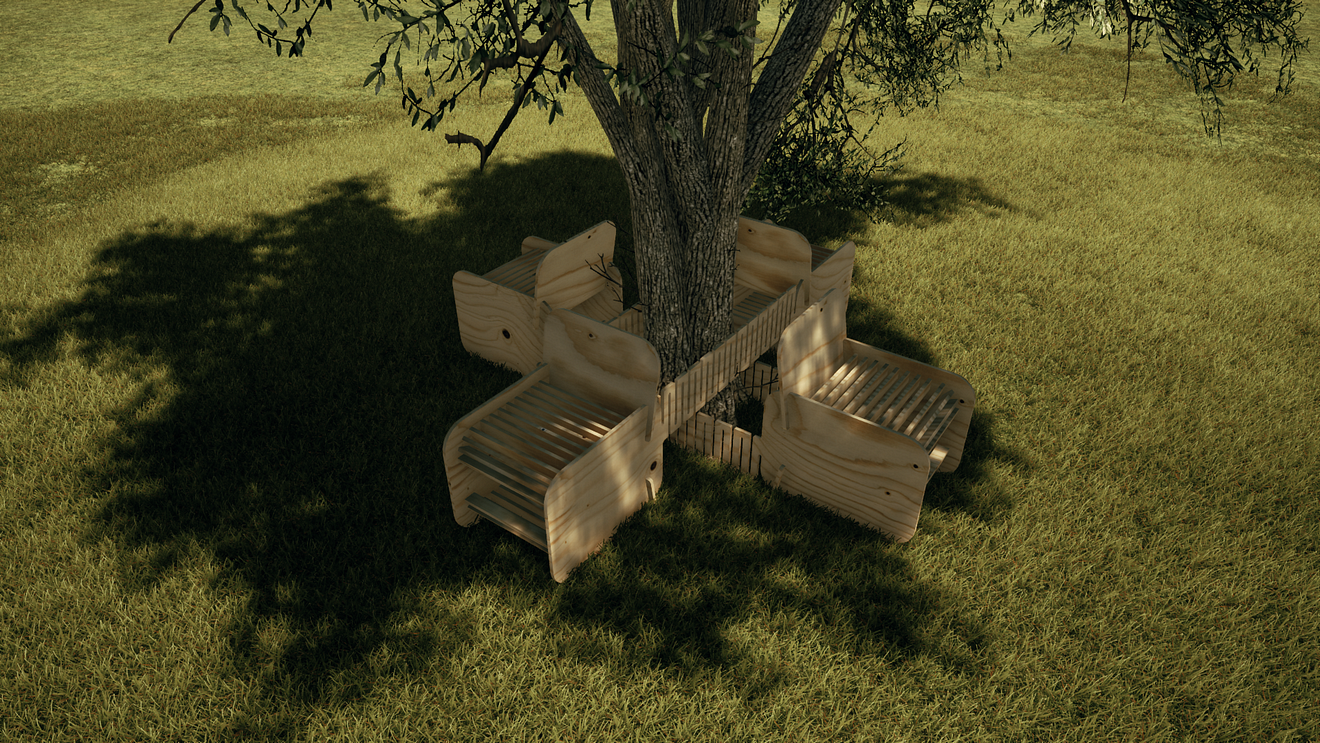
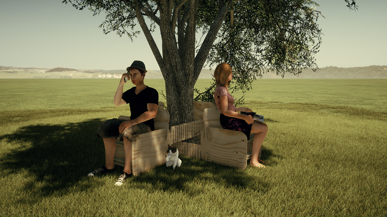
I always thought that one of the most comfortable places to sit or rest in an urban context is under a tree, unfortunately, this idea is not widely implemented for urban furniture.
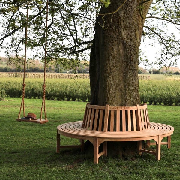
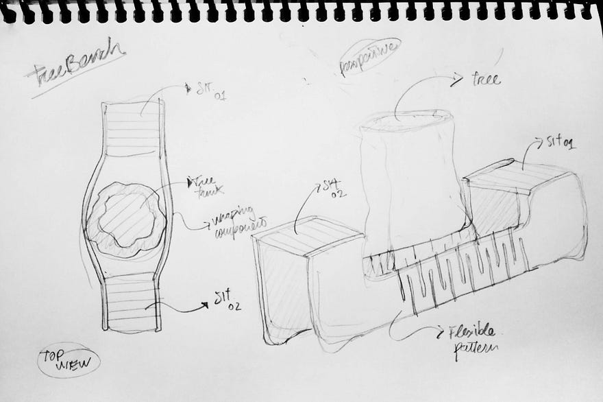
Tree Bench by The Oak and Rope Company
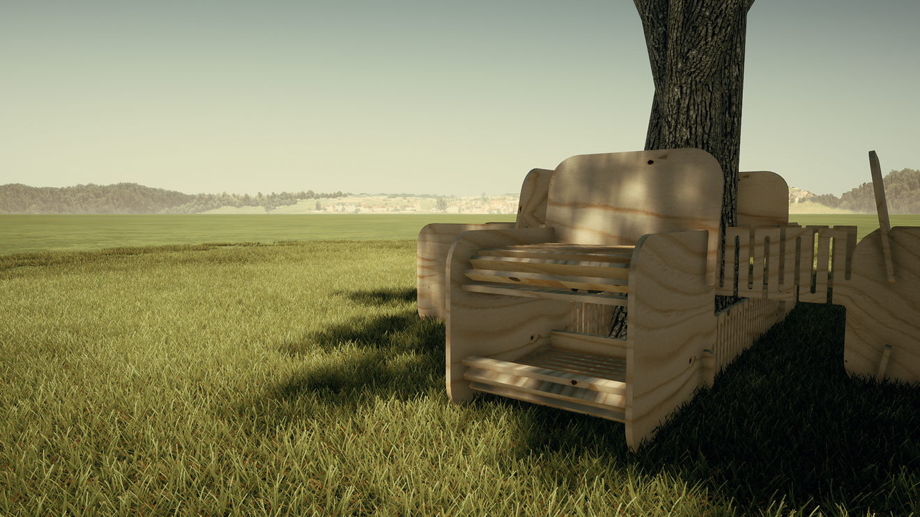
My idea is to produce an urban bench that could use the shadow cast by trees. The design would wrap around the tree trunk with a flexible part and the sitting component would close the loop. making the final shape adapt to the tree diameter or geometry.
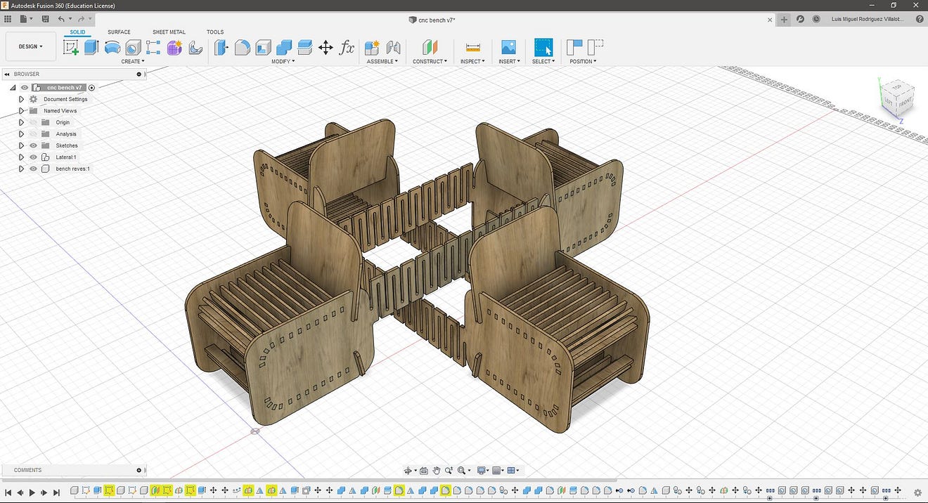
Development with Fusion 360
I decided to use Fusion 360 for the CAD and CAM to make a parametric design. I explored Fusion capabilities before on Computer-aided Design and Computer-controlled cutting assignments.
Here’s a video of the design workflow for the tree bench:
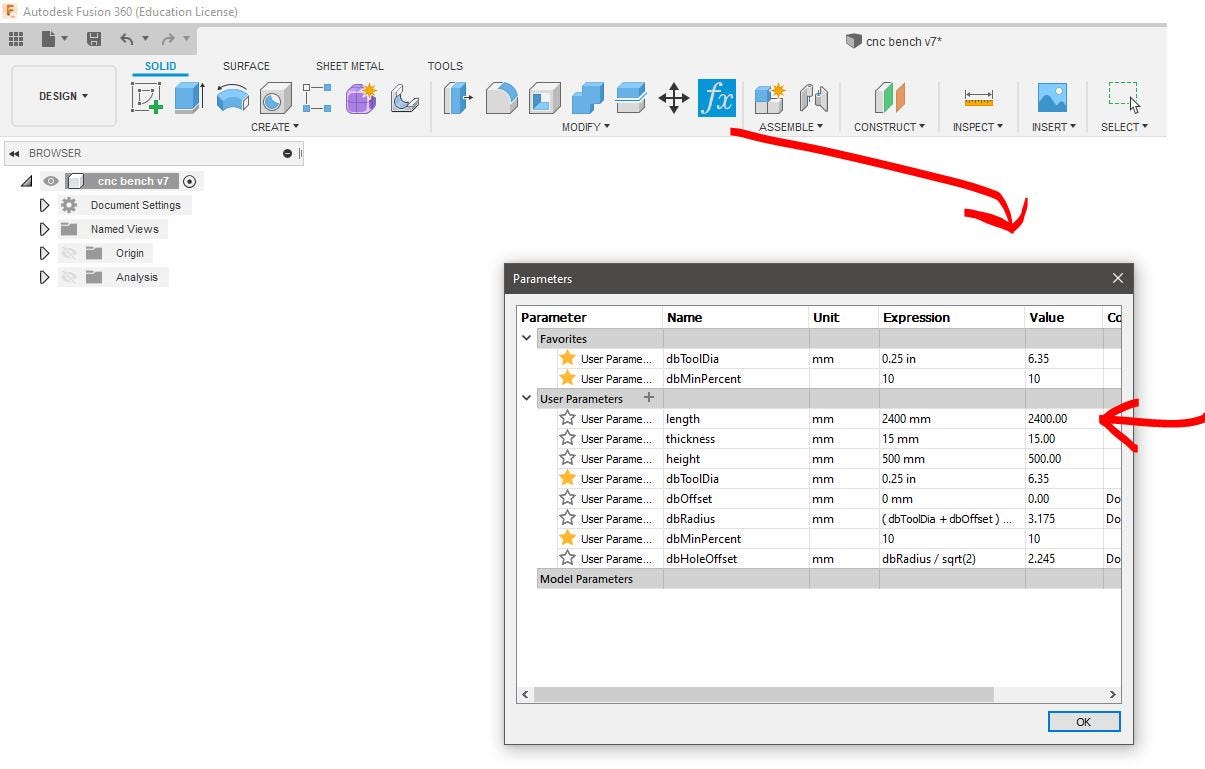
First I start defining the parameters for the length of the material (2400mm) and the thickness (15mm)
The usual workflow for Fusion starts with creating a new component and making a sketch. This is a 2D drawing of the part we’ll be extruding.
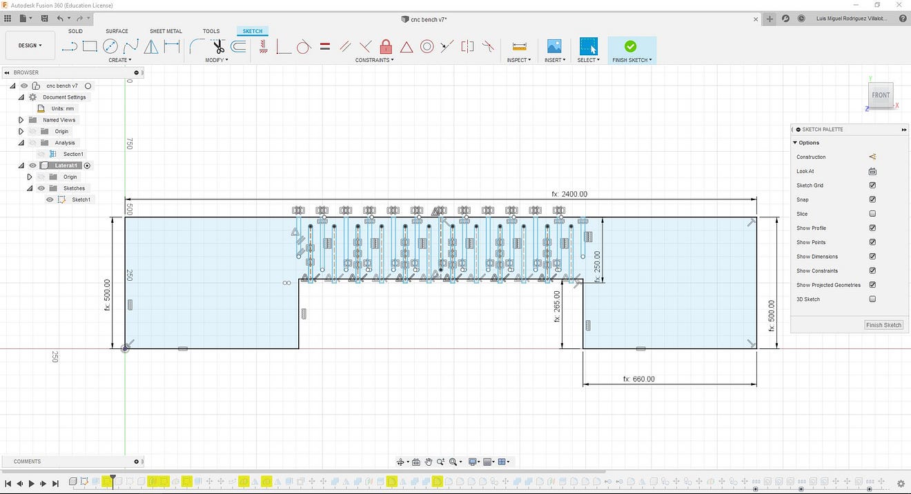
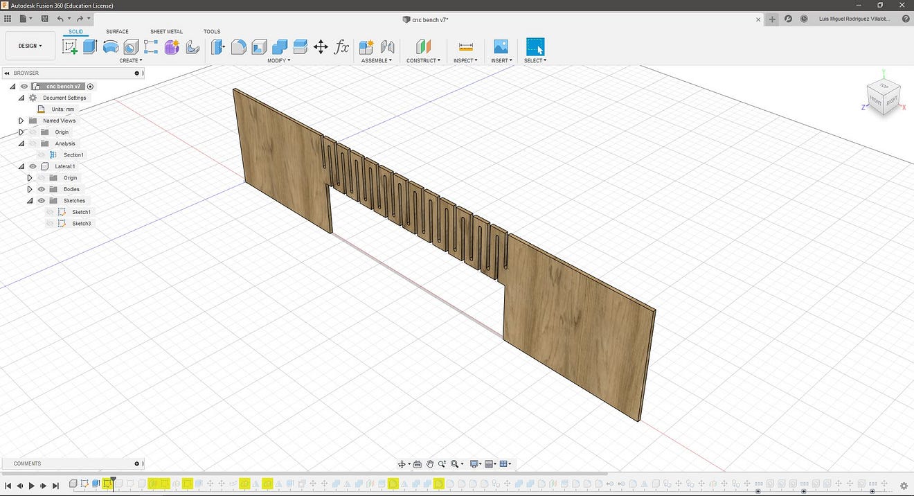
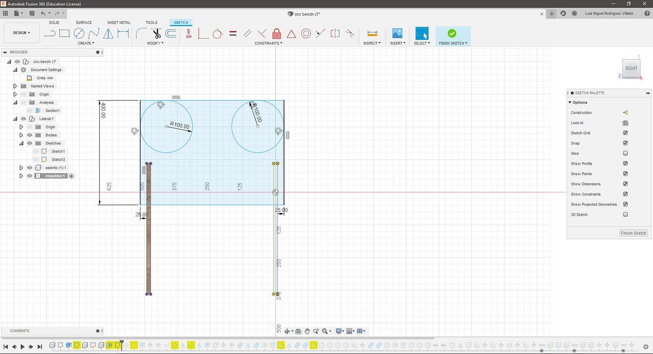
I started with the side panels, for this sketch I used the length parameter and some other fixed dimensions (Fx) like the height of the seats on the sides (500mm), the bottom part that will be in contact with the ground (660mm) and the clearance for the flexible part (265mm). Notice that I also used constraints to keep these dimensions equal.
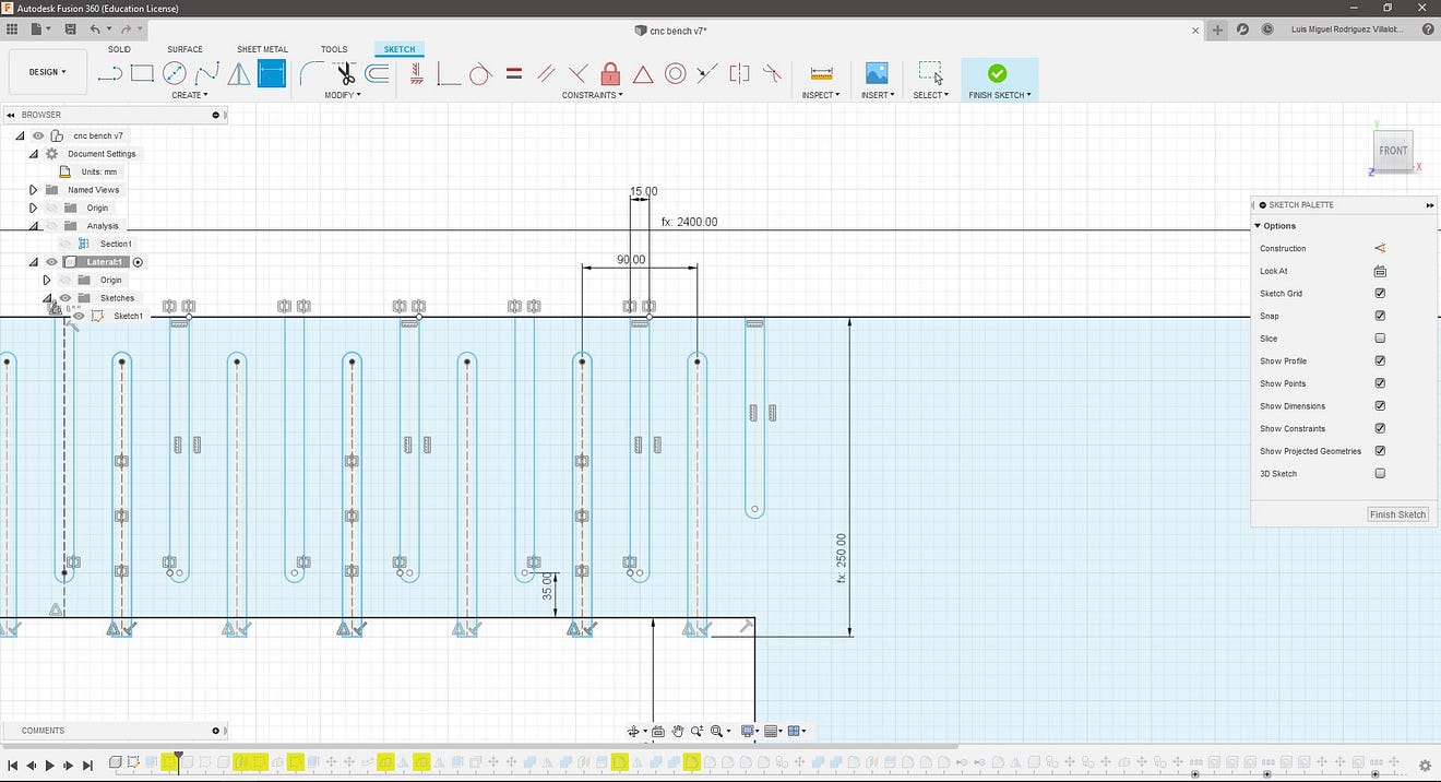
For the flexible pattern, I used a lattice hinge with the help of this guide. The groove is equal to the thickness and the distance between two is thickness*3.
After the sketch is finished I extruded the component using the thickness parameter.
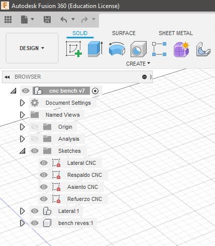
I repeated these steps to create the backrest and the sitting.
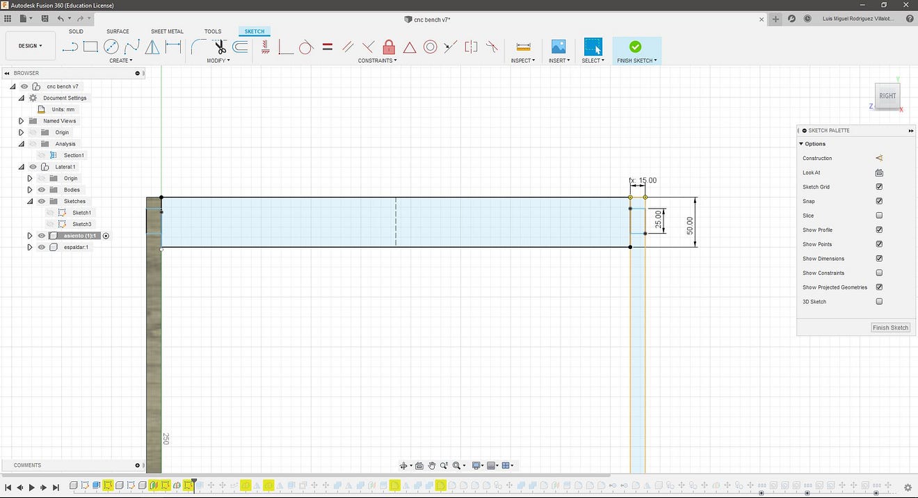
The sitting part was created using the array along a path (path created with a sketch) as the design is symmetric I mirrored these “features” using construction planes along the vertical a horizontal axis.
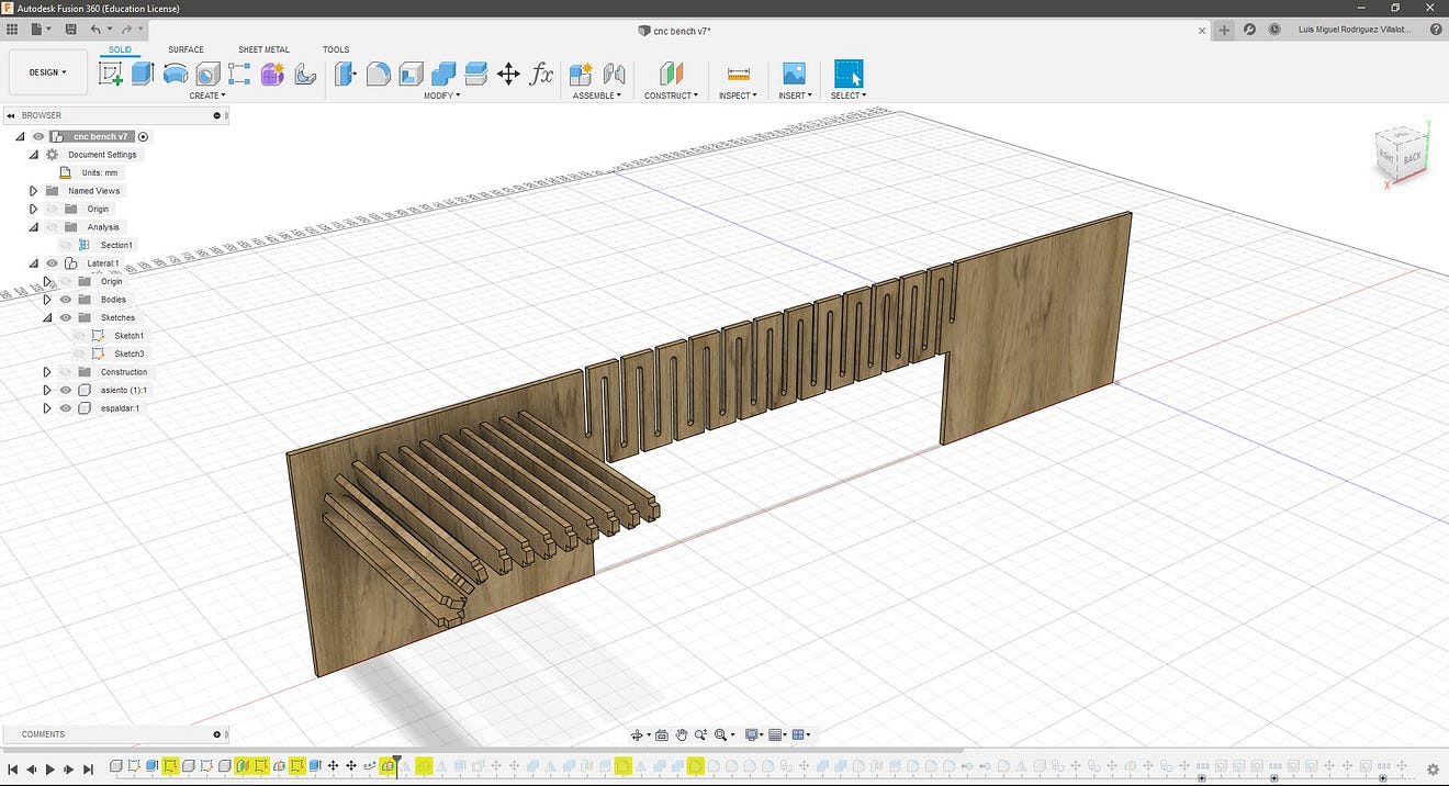
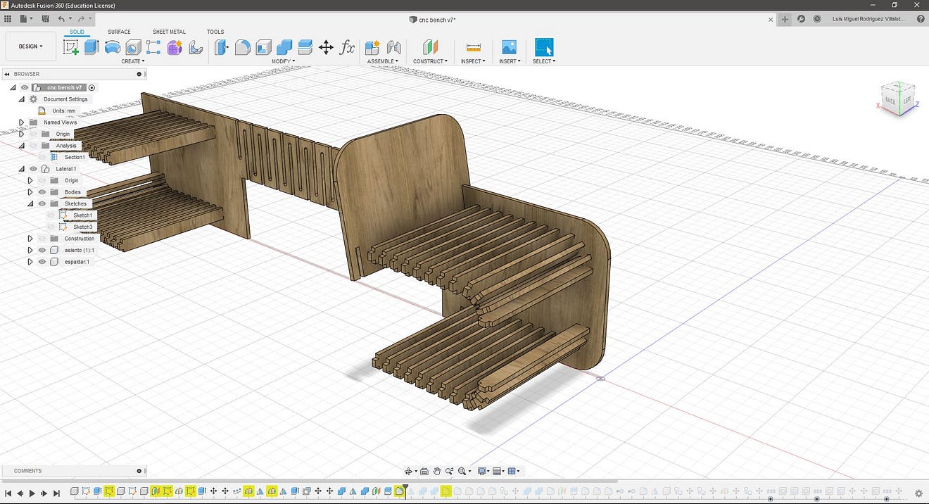
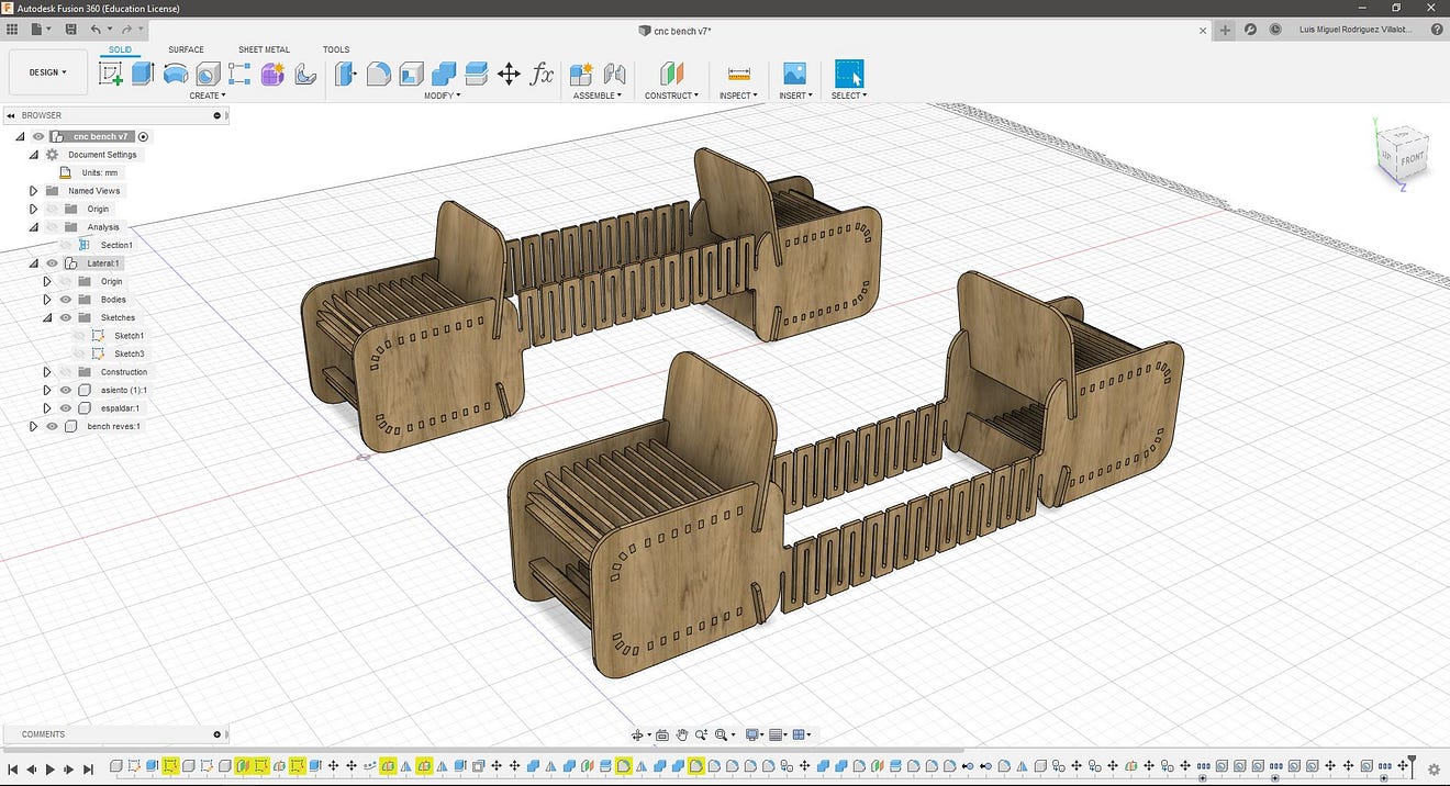
I later copied the side component to close the design and used the combine/cut tool to make the holes for the sitting and the backrest to slide into these pieces. The backrest works securing the side pieces and there is a second bottom component with this purpose too. This was made by mirroring the backseat and cutting it with a construction plane, this solution allows the design to be used upsidedown.
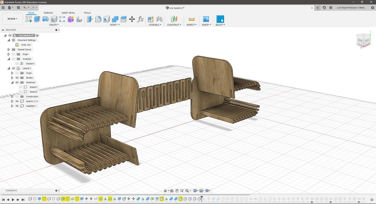
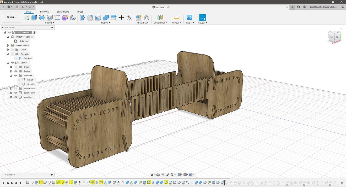
To finish the design I used the fillet tool to round up the edges.
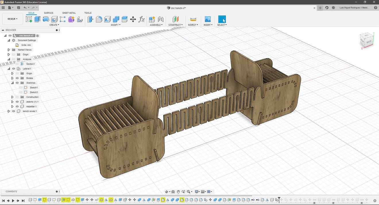
I later created a new component and copied all the parts to make the inverted version of the bench, in this way these two benches could be placed around a tree to have a 4 sitting space.
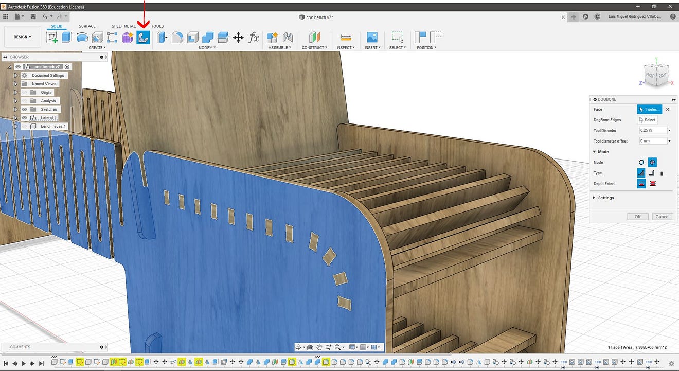
To make the dogbone features I used a Fusion 360 add-in that can be found and downloaded here, this works by selecting a face, selecting the tool diameter (0.25in) and the add-in will find the edges perpendicular to the selected face and the applying a circular cut.
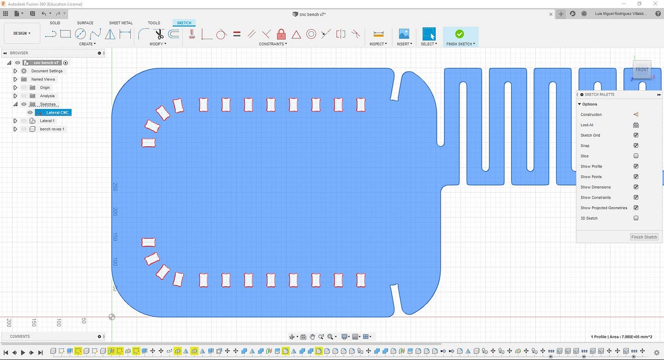
To make a 2D cutting profile from this face, we need to make a new sketch. This is made clicking the face and then hit finish sketch. These sketches will allow us to export them as .dwg files.
To finish I tried some of the built-in render capabilities of Fusion 360.
This is the final image:
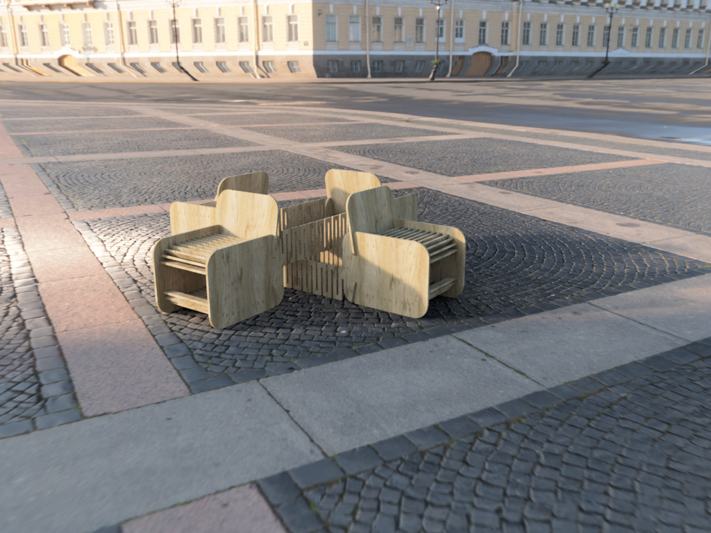
As I could not add a tree to the render in Fusion, I exported the model in Sketchup format to use Twinmotion render engine. Fusion works on the could but allows exporting the file to multiple 3D formats.
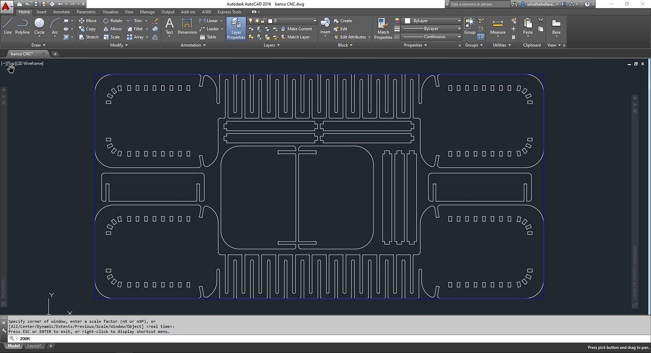
To prepare the design for machining I placed the exported .dxf files in a single file, placing them inside a rectangle according to the measurements of the board (1200 x 2400mm).
Machining Process
As the covid restrictions are STILL in place in Peru, and I had limited fablab access and machining time I choose to change my original design. The machining was made in FabLab iFurniture and thanks to the help of its founder Vaneza Caycho, from here a big shout out for the support!!
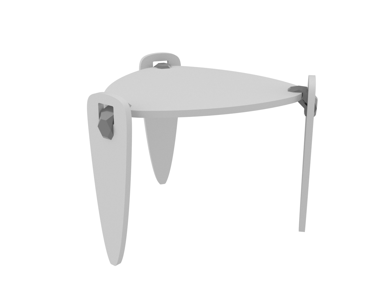
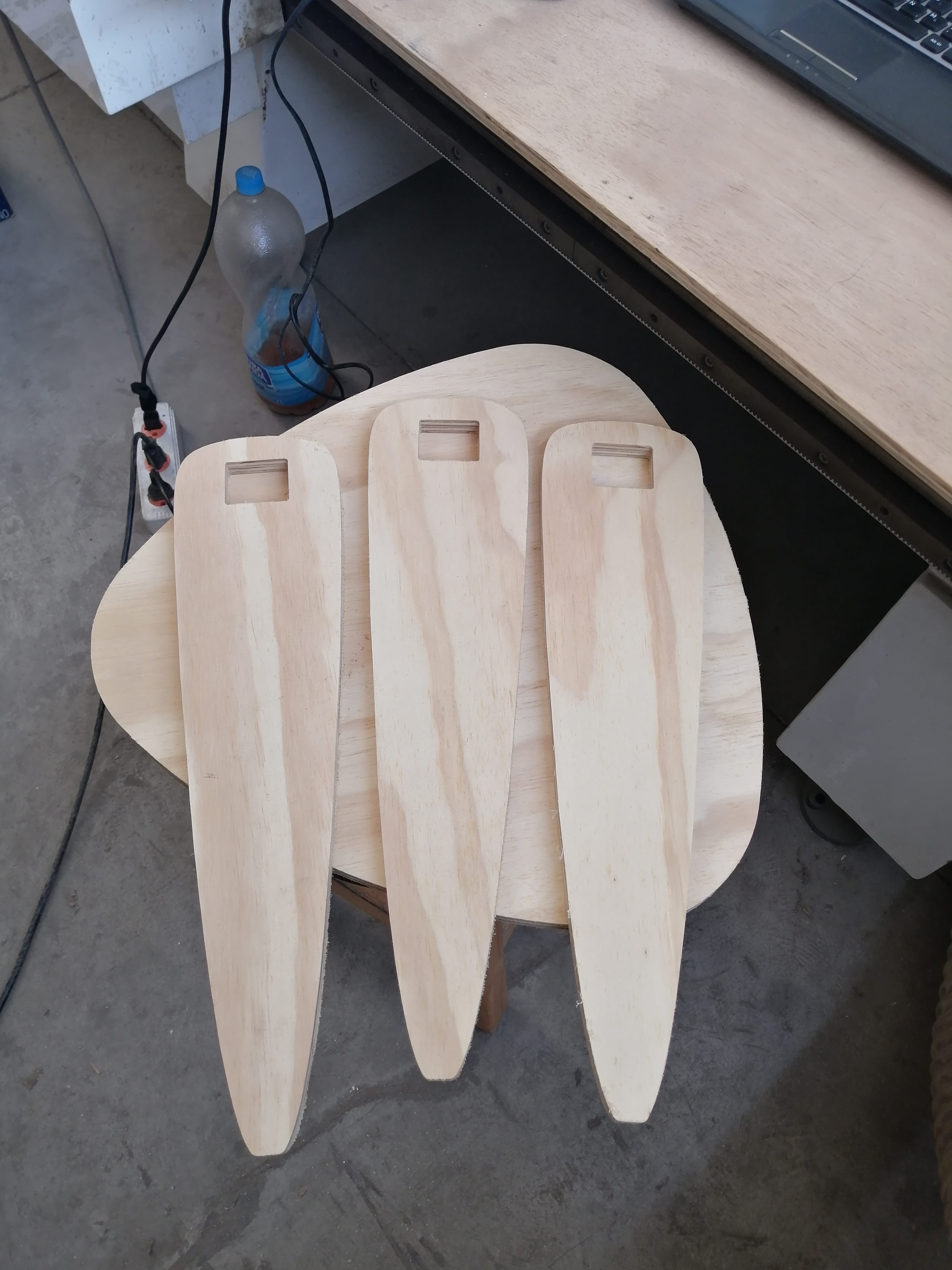
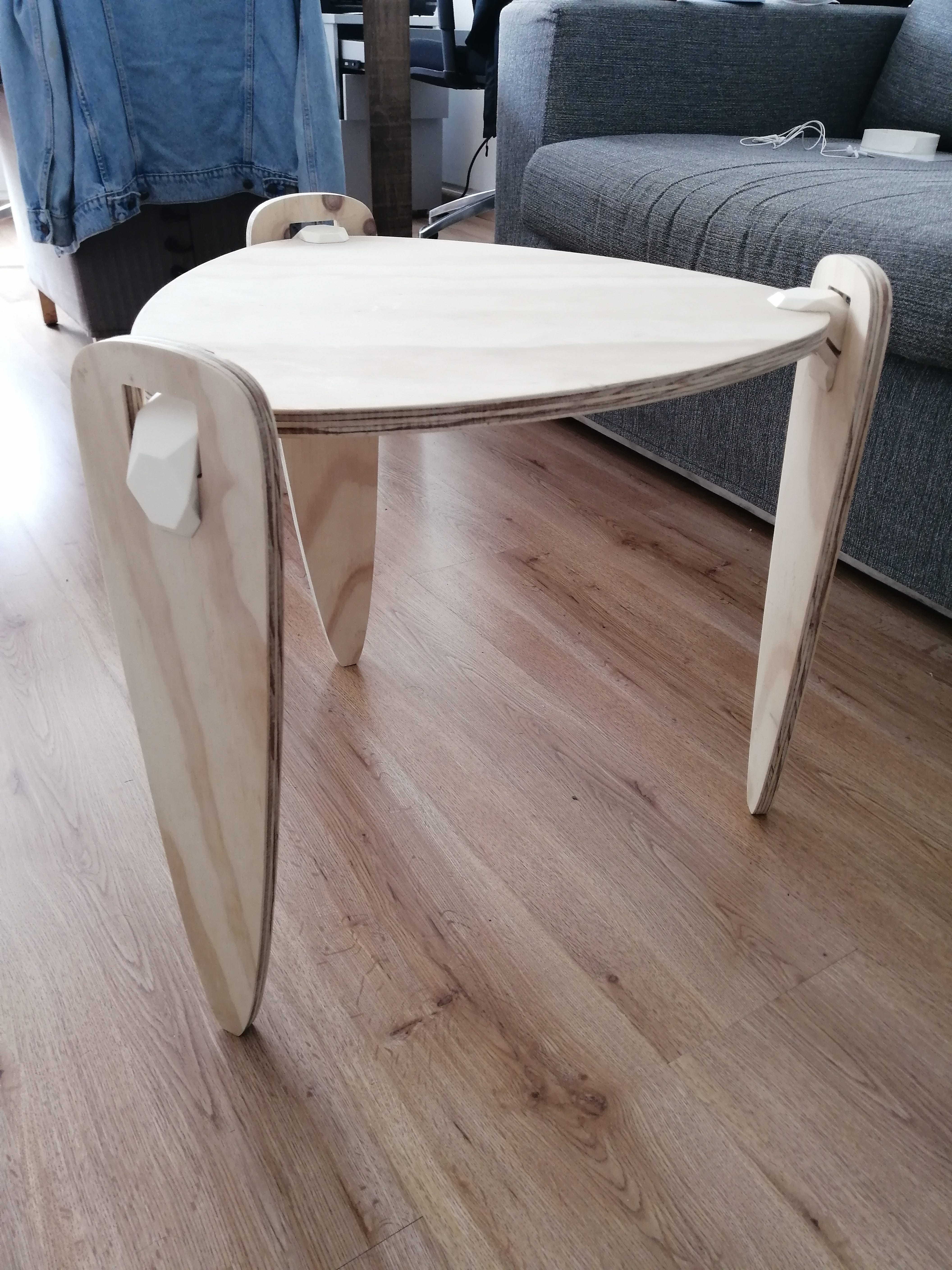
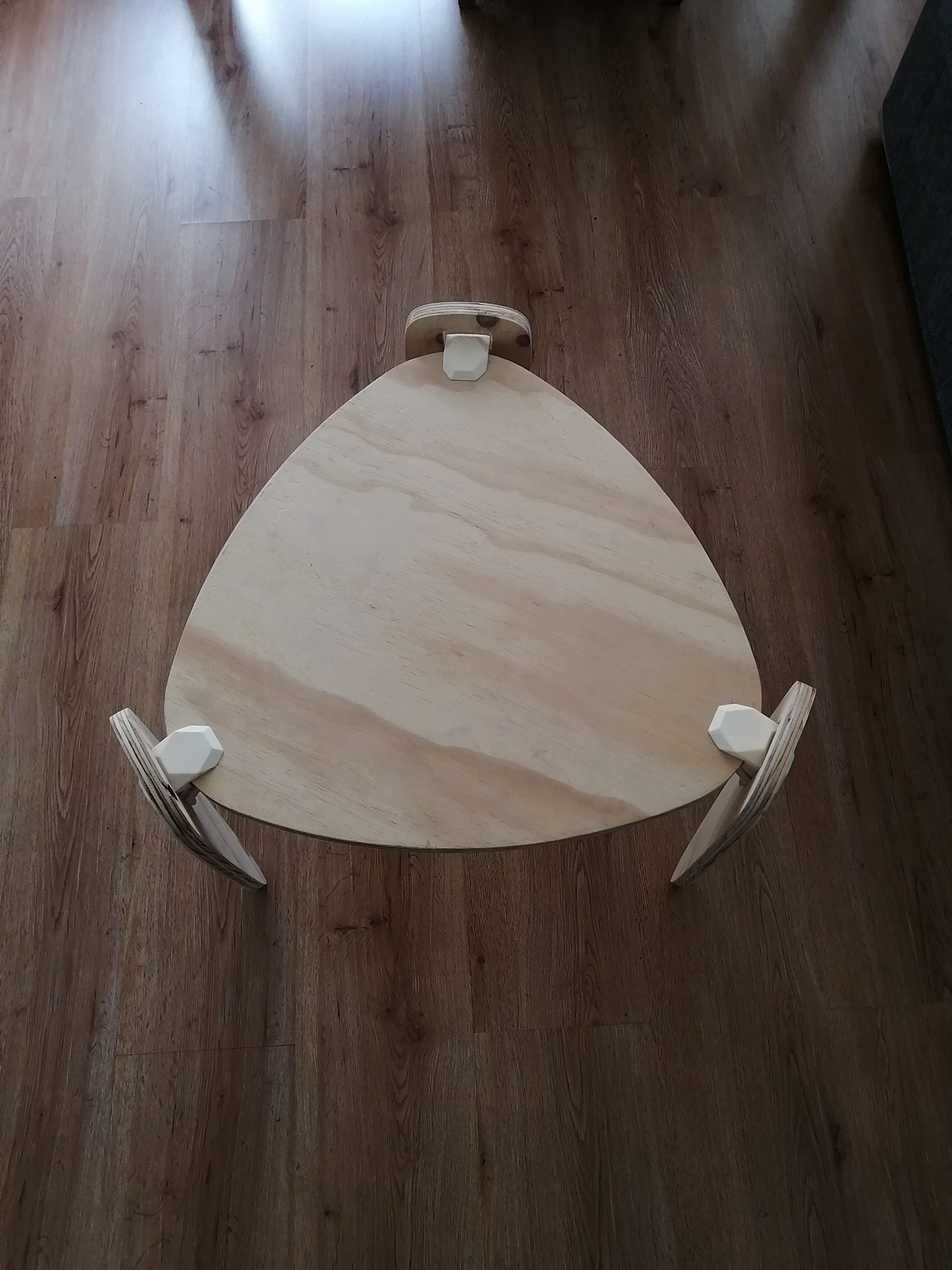
The new design is a three-leg coffee table with a Realeaux triangle tabletop, making it 4 pieces for machining in a 60cm by 1.2m plywood sheet (so, around 1/4 of a full sheet) these parts will join by resin-casted joinery made with the techniques learned through molding and casting.
The first step is to process the cutting files, I’ll be working with ArtCam software from Autodesk. Sadly is discontinued, but that’s the software the workshop uses and works with the CNC router.
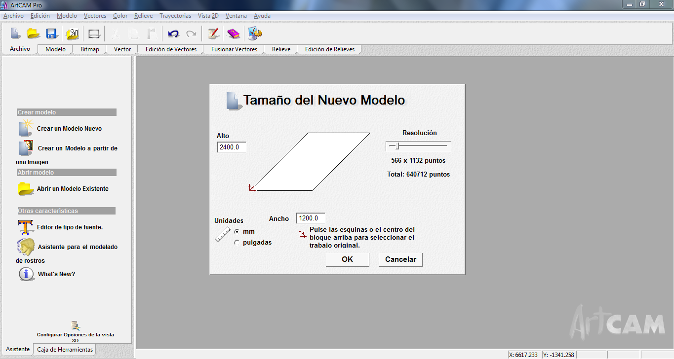
The process is pretty straightforward, first, we set the machining sheet (1200m x 2400m) and the origin of the router in the bottom-left corner and import the file in .dxf format (sorry Neil!)
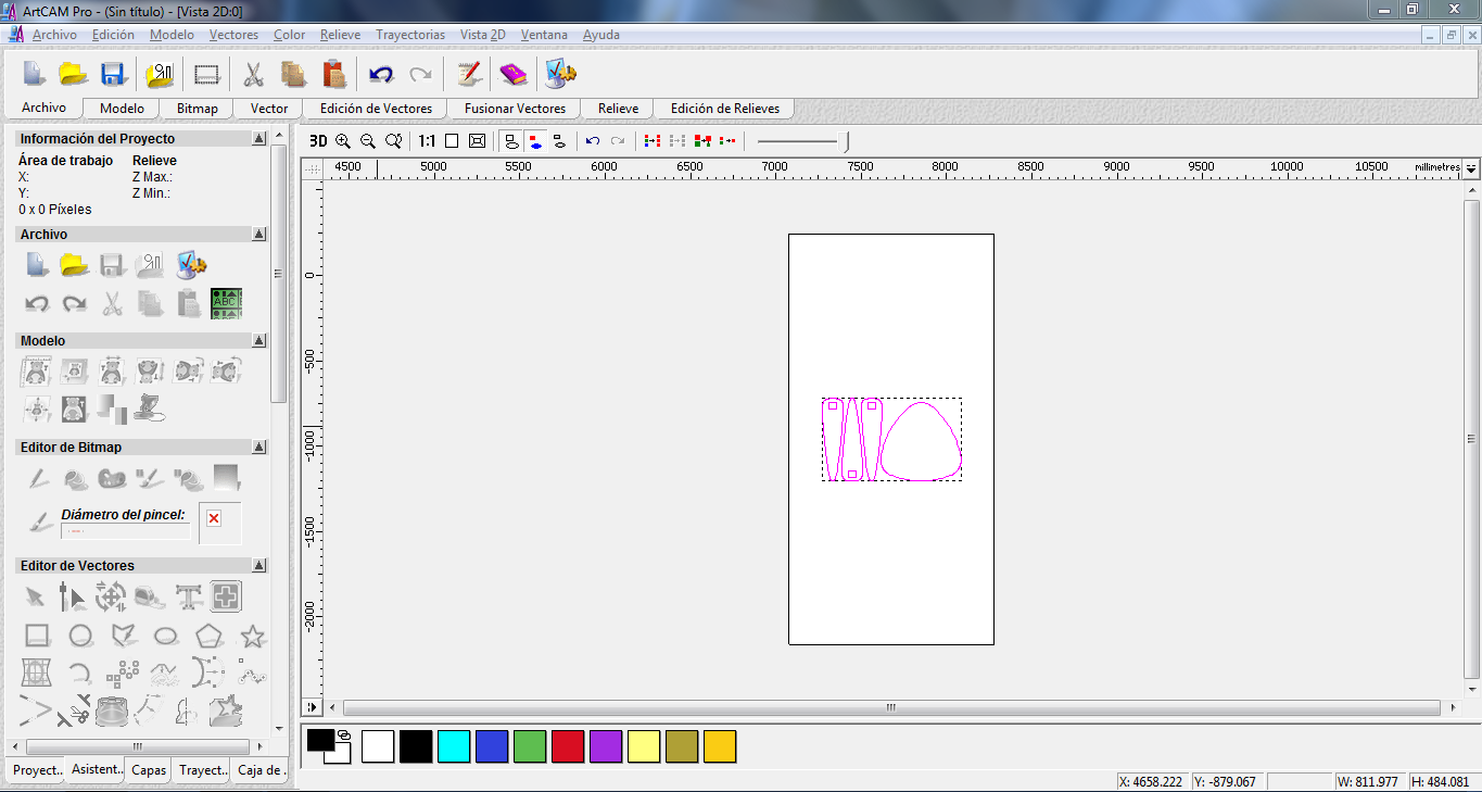
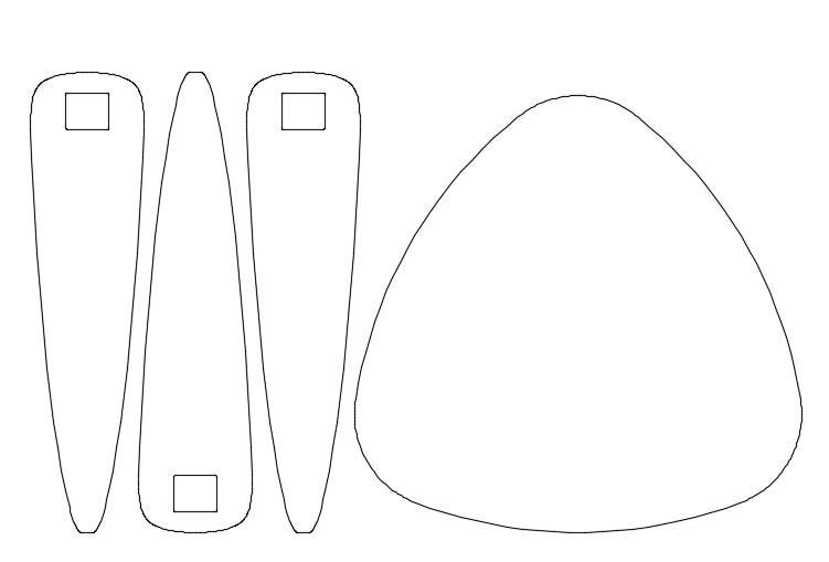
I selected the three legs first to test the cutting settings, I'll be using a 3mm end mill with the settings shown below:
The next steps are to set the inside and outside cuts selecting the lines, the inside cuts are the small squared holes on top of the legs to hold the joins in place and the outside is the perimeter of the piece. The settings are the same for inside and outside cuts.
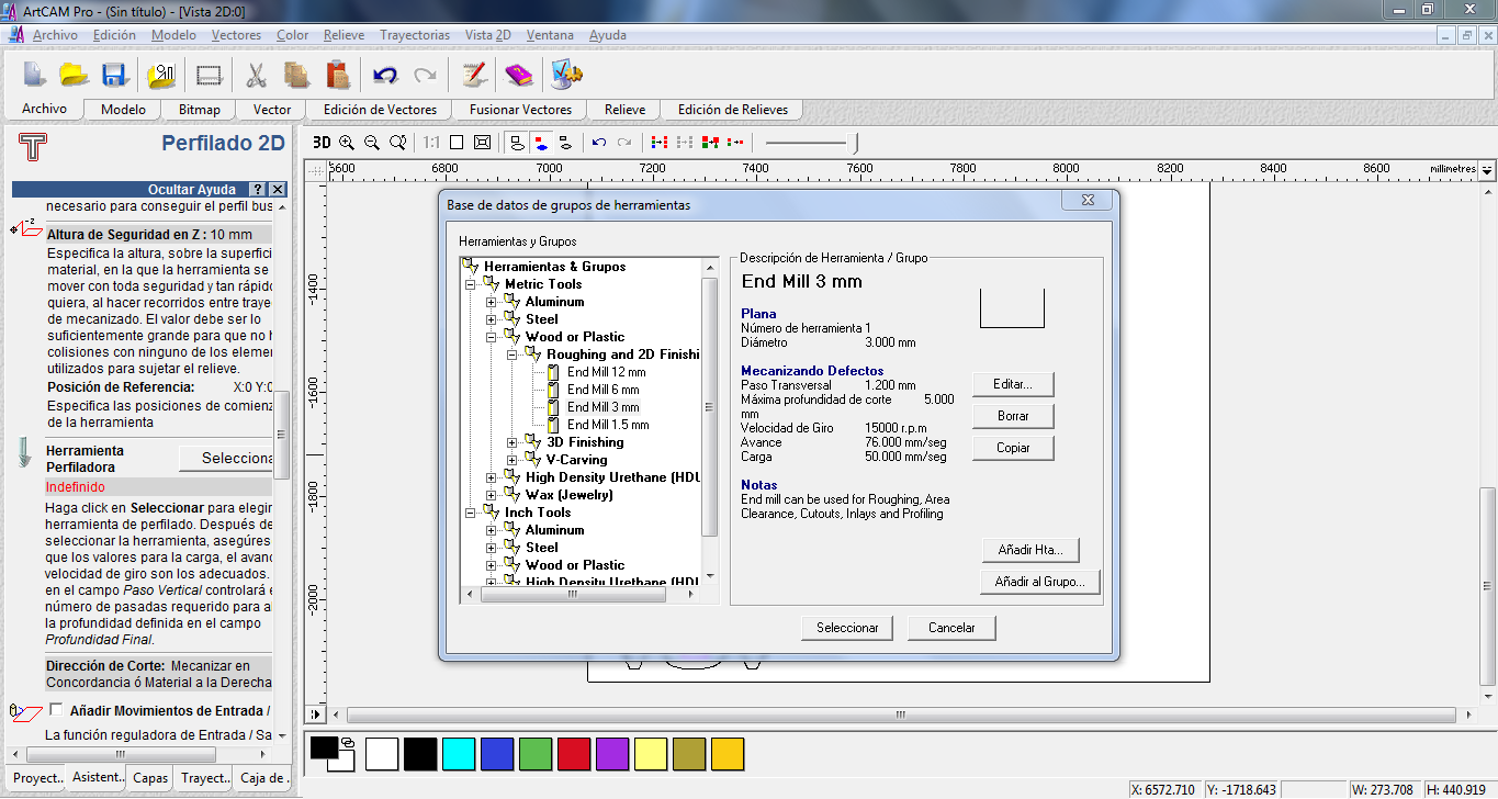
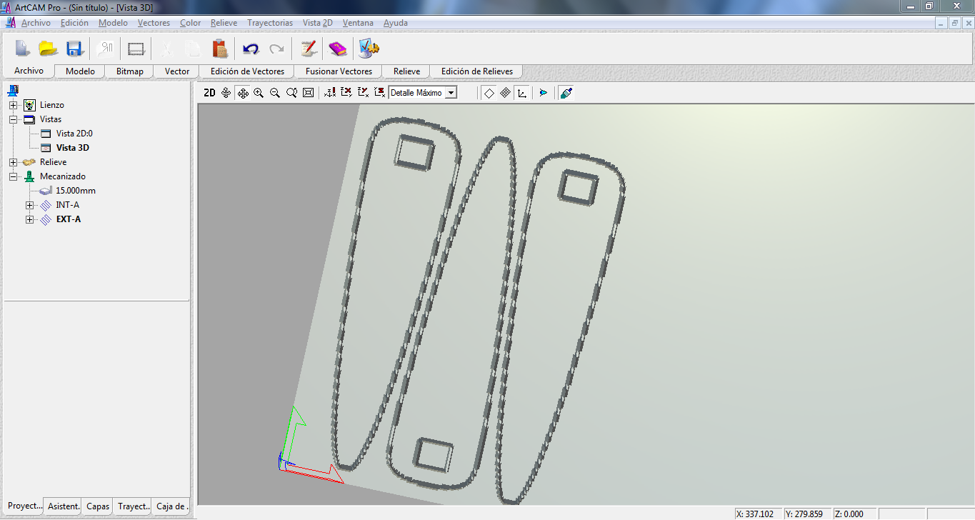
This is the simulation for the milling path of the inside cuts.
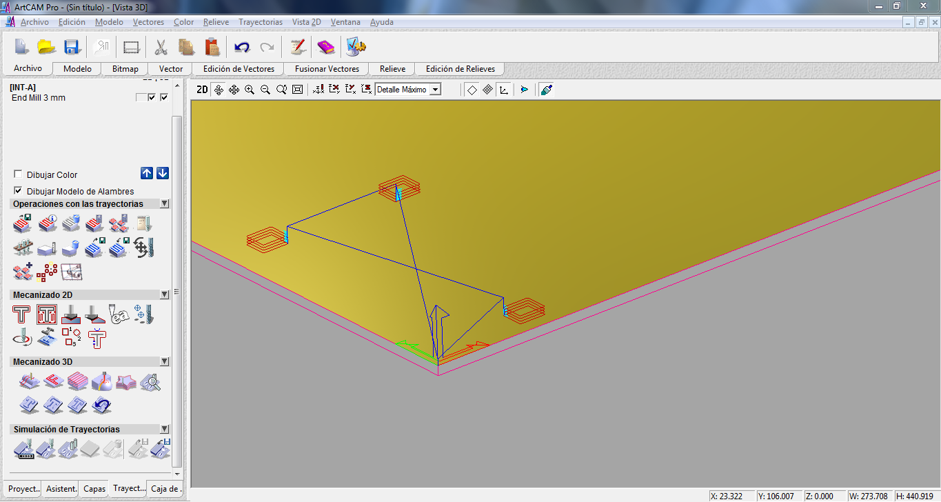
The simulation for the milling paths with outside and inside cuts.
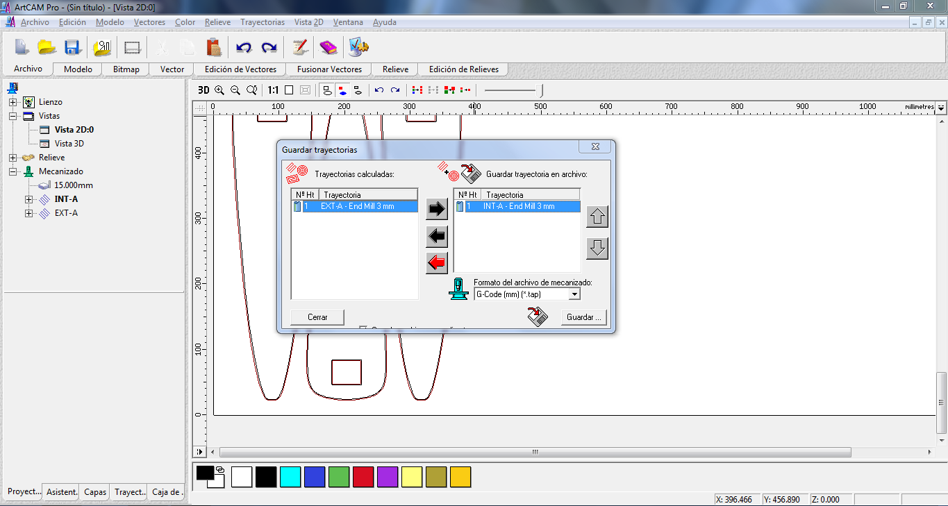
We export both cuttings paths to a G-code file format called .tap and the loaded to the USB drive that goes in the CNC controller.
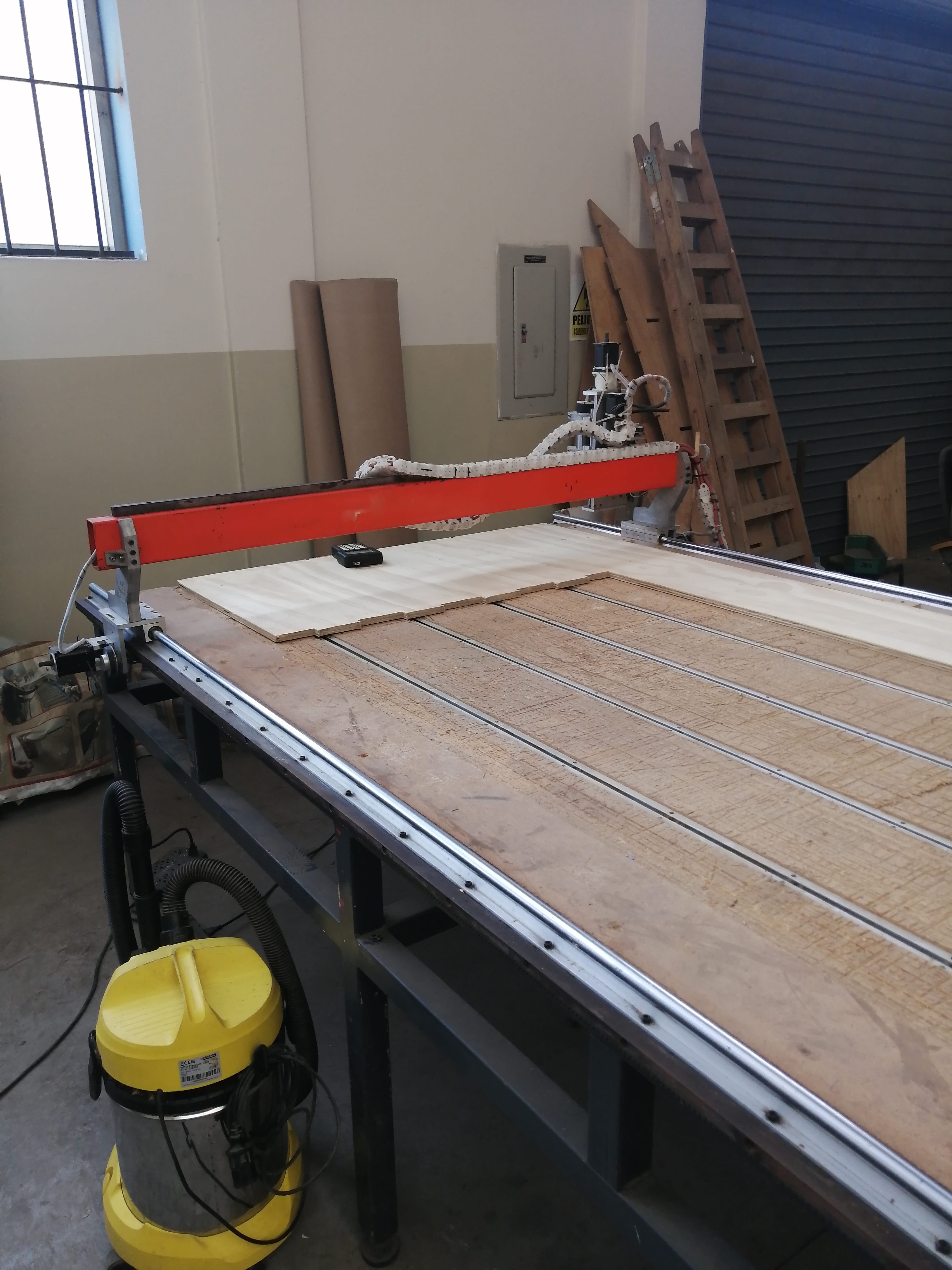
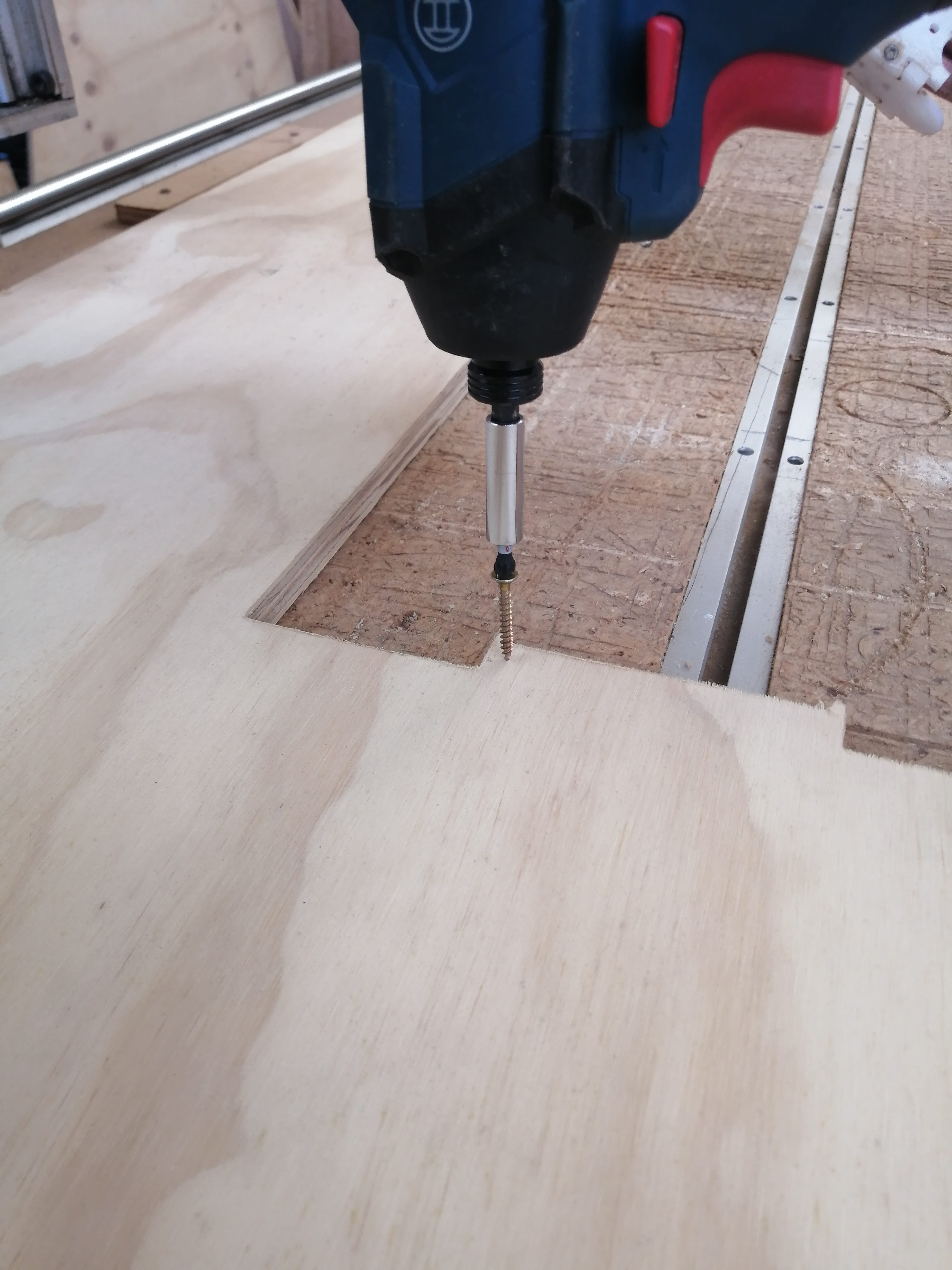
Now is time to set the plywood sheet on the CNC router bed. I’ll be using 15mm plywood, and as you can see, only a portion of the sheet will be used. The sheet is secured by woodscrews on the outside corners and the middle, it is very important to set a secure working offset for not having the screws on the cutting path.
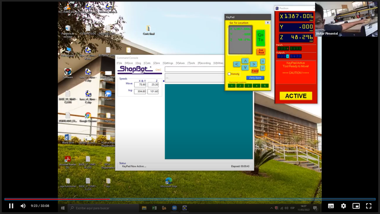
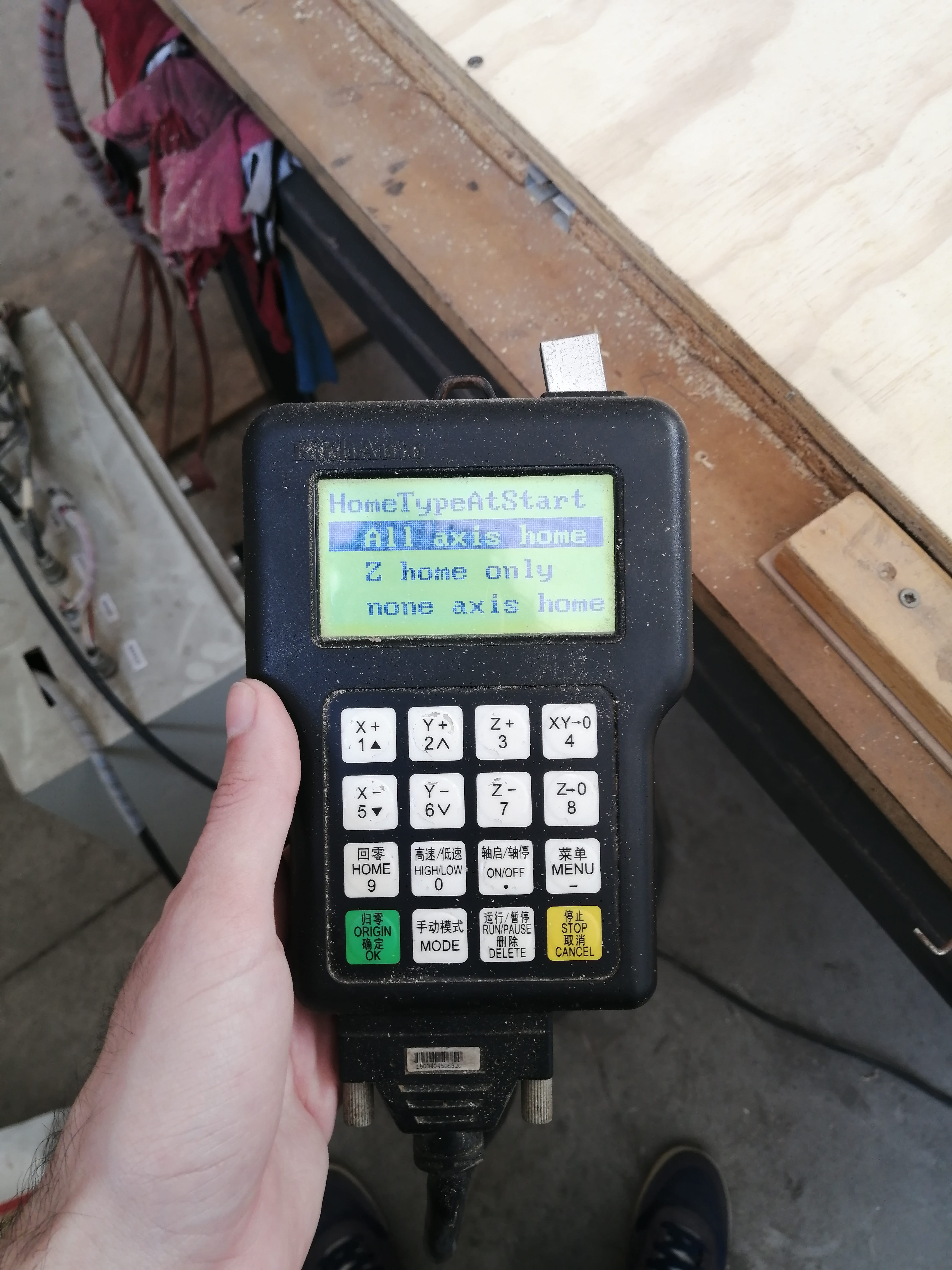
To set the HOME position we press the origin button (in green) and then select All axis home, this will move the router to its default home position, we can change this by moving the three axis with the X, Y, and Z buttons. This will allow setting a proper working offset.
A crucial part is setting the Z-axis that controls the elevation of the router. This is manually set by moving the endmill to slightly touch the cutting material.
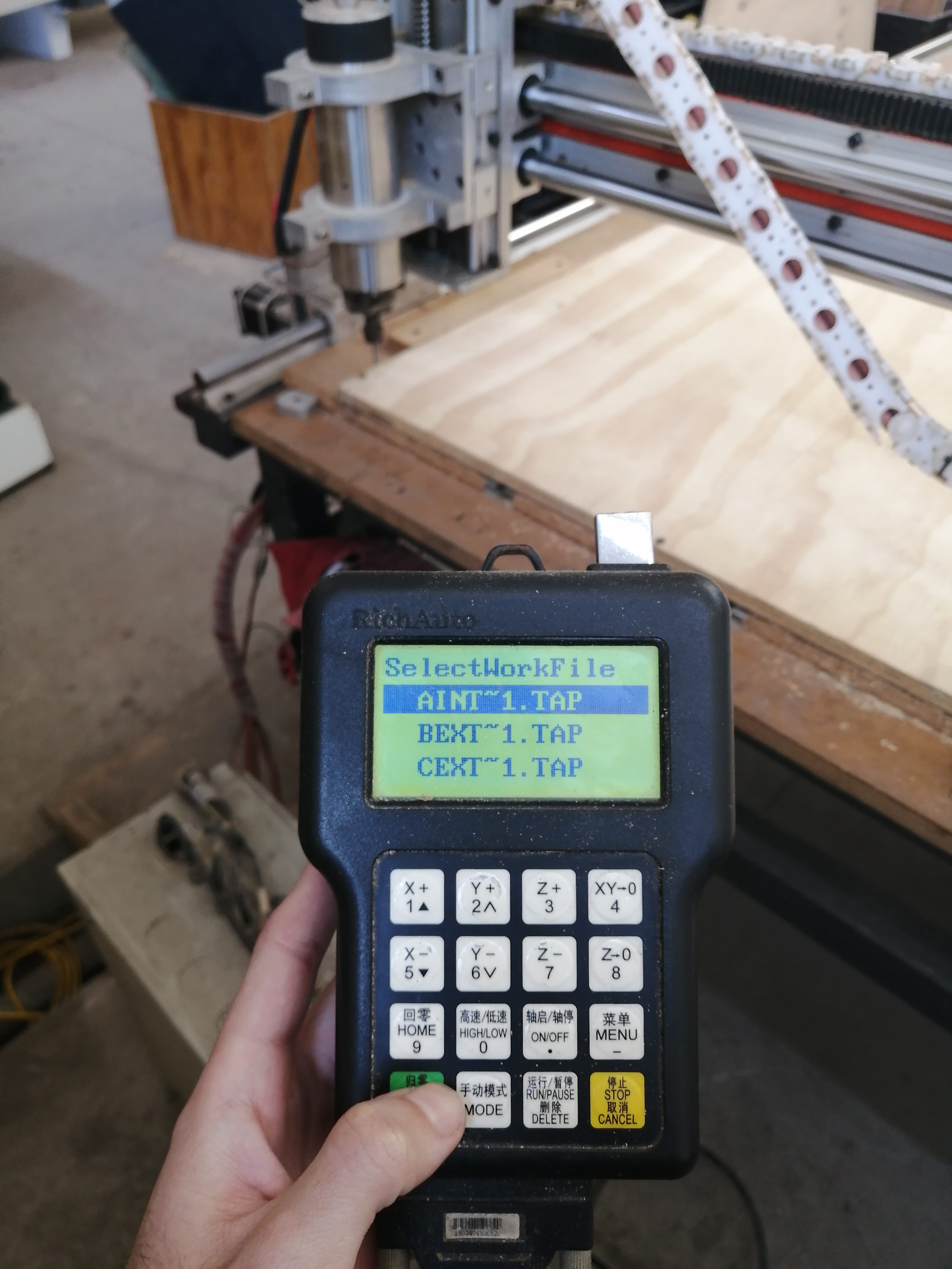
With all the axis set, we are ready for machining! so select the files from the controller, notice the USB drive plug in the top right corner of the controller.
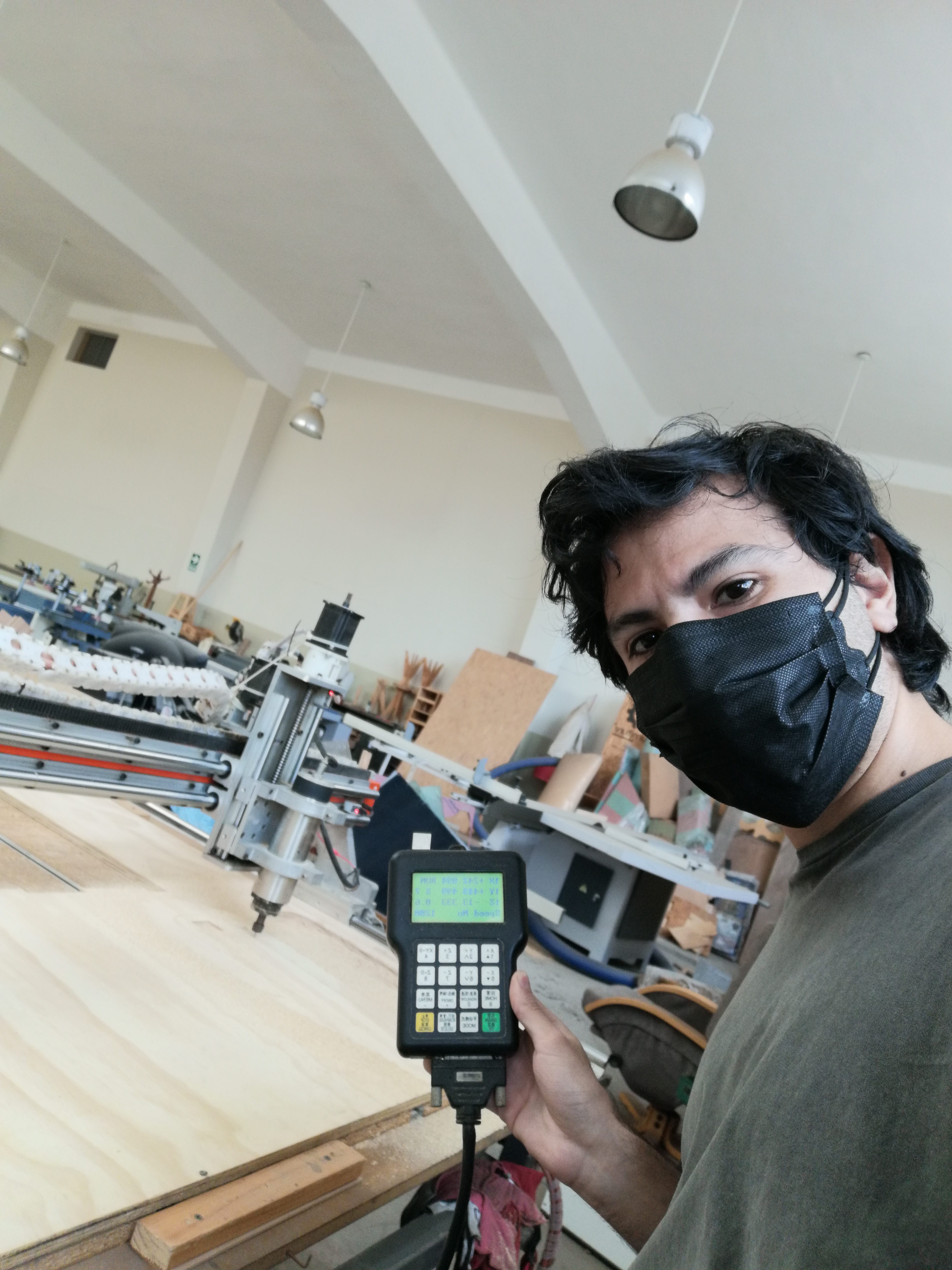
Let the CNC Machining begin!
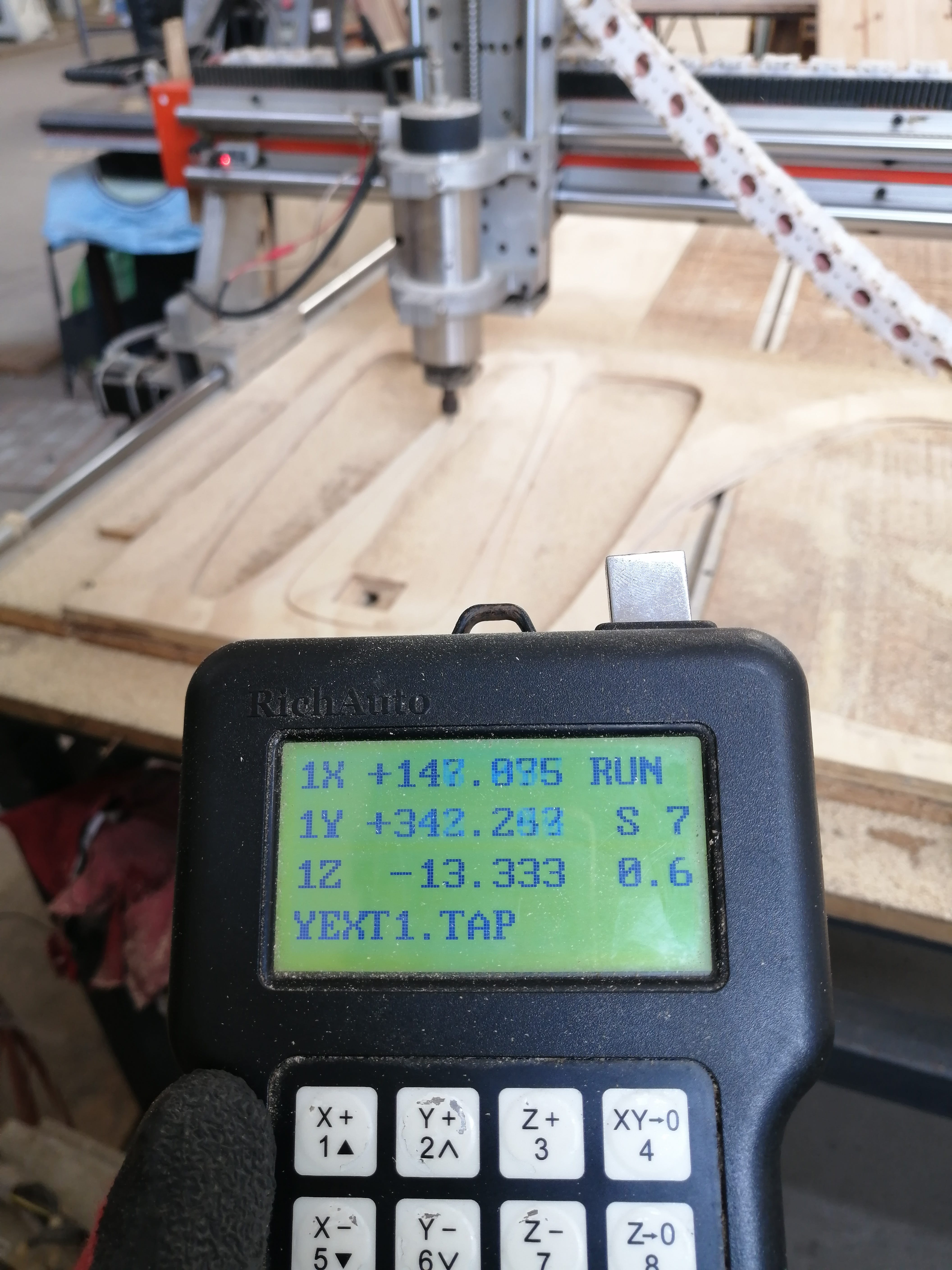
The cuts went smooth, the axis movement can be seen in the controller screen in real-time. The total machining time was around 20 minutes. This machine (custom made) has a small router motor, so it plunges less deep and moves slower than a regular shopbot.
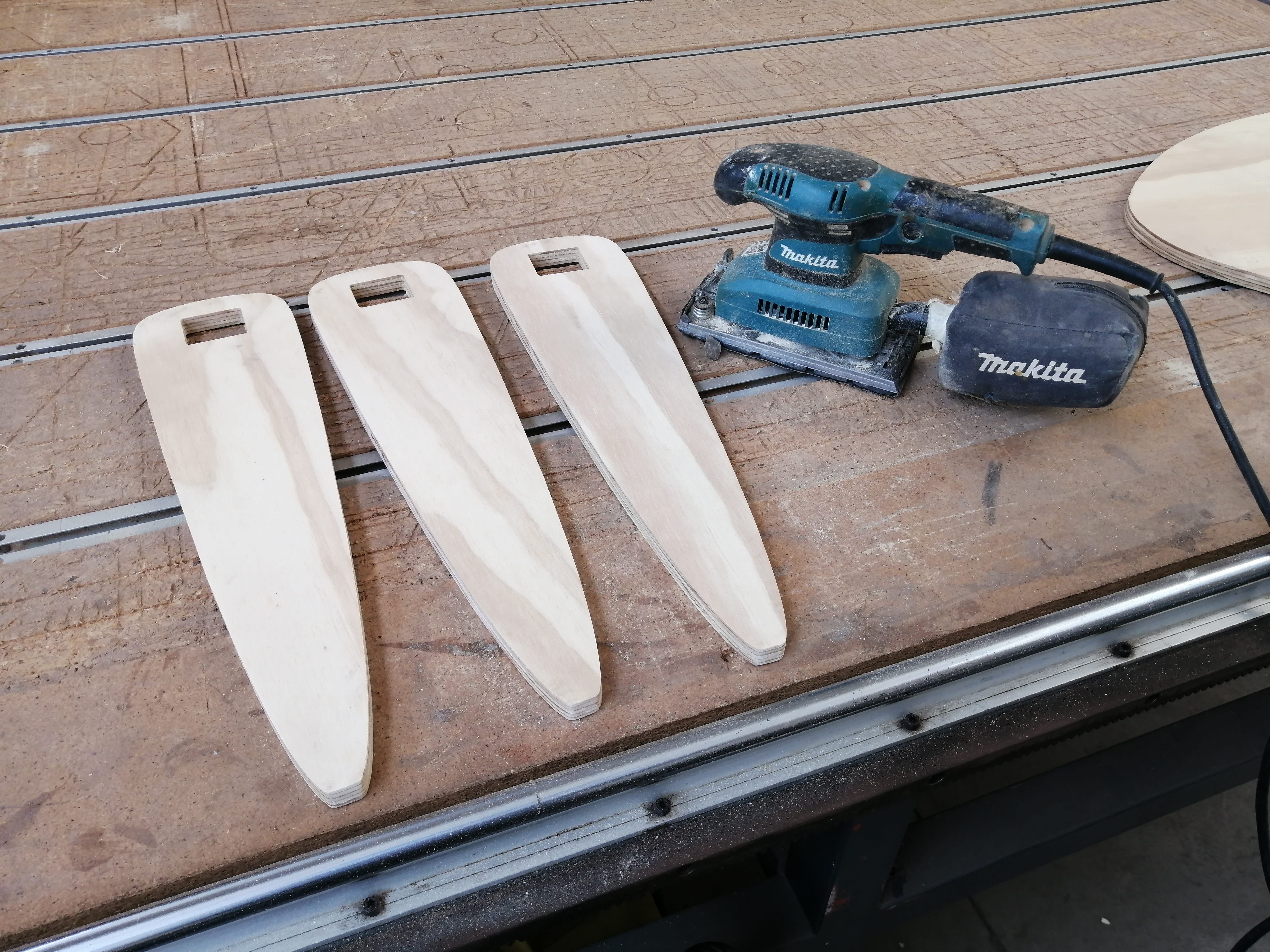
The four parts after the machining came out with the edges almost clean of debris, I was using a brand new endmill and it was an up-cut bit. Some light sanding and the parts were ready to assemble.
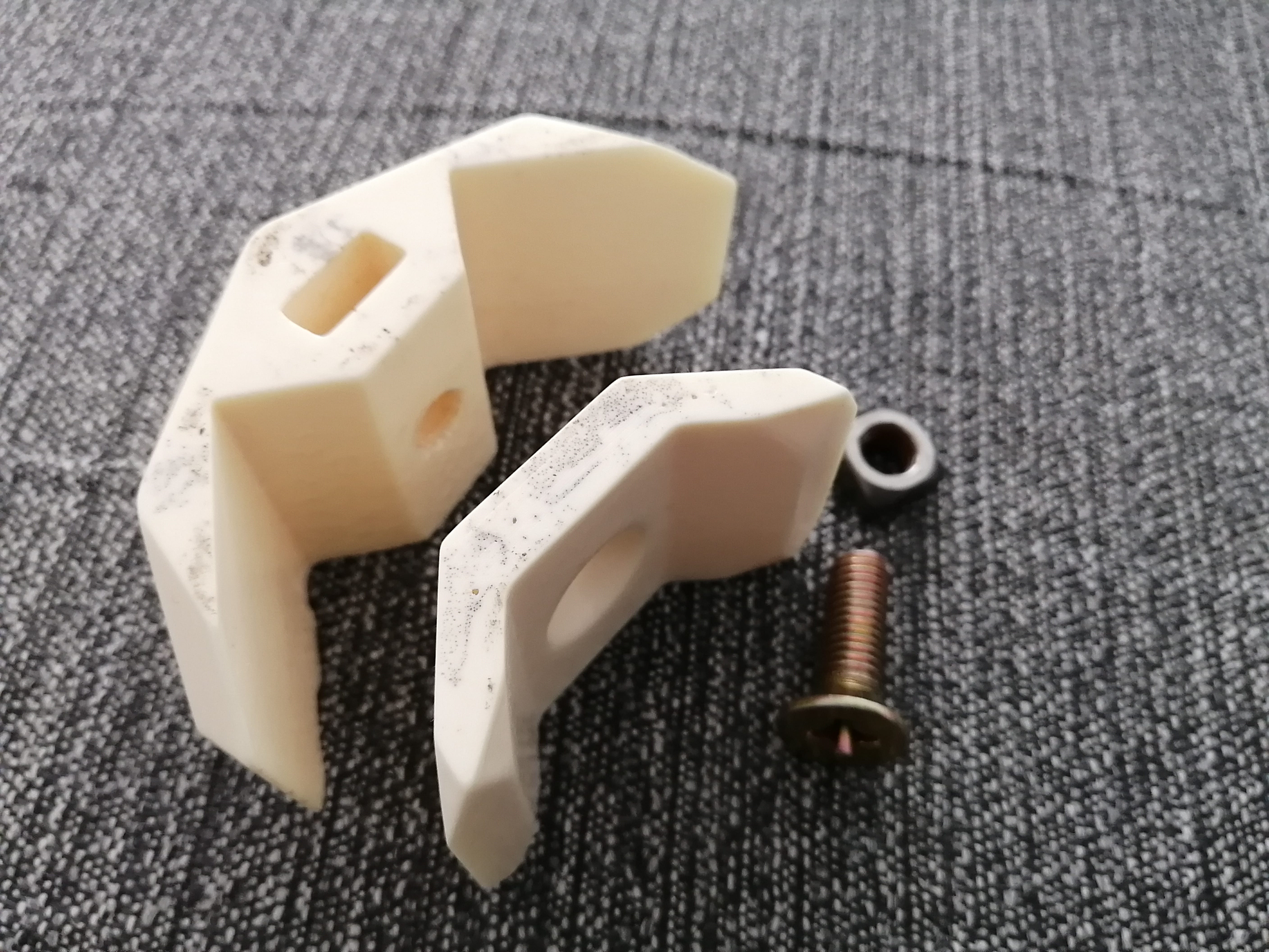
For the joints I’ll be using polyurethane resin cast parts, these were made with 3D printing, silicone molding, and resin cast.
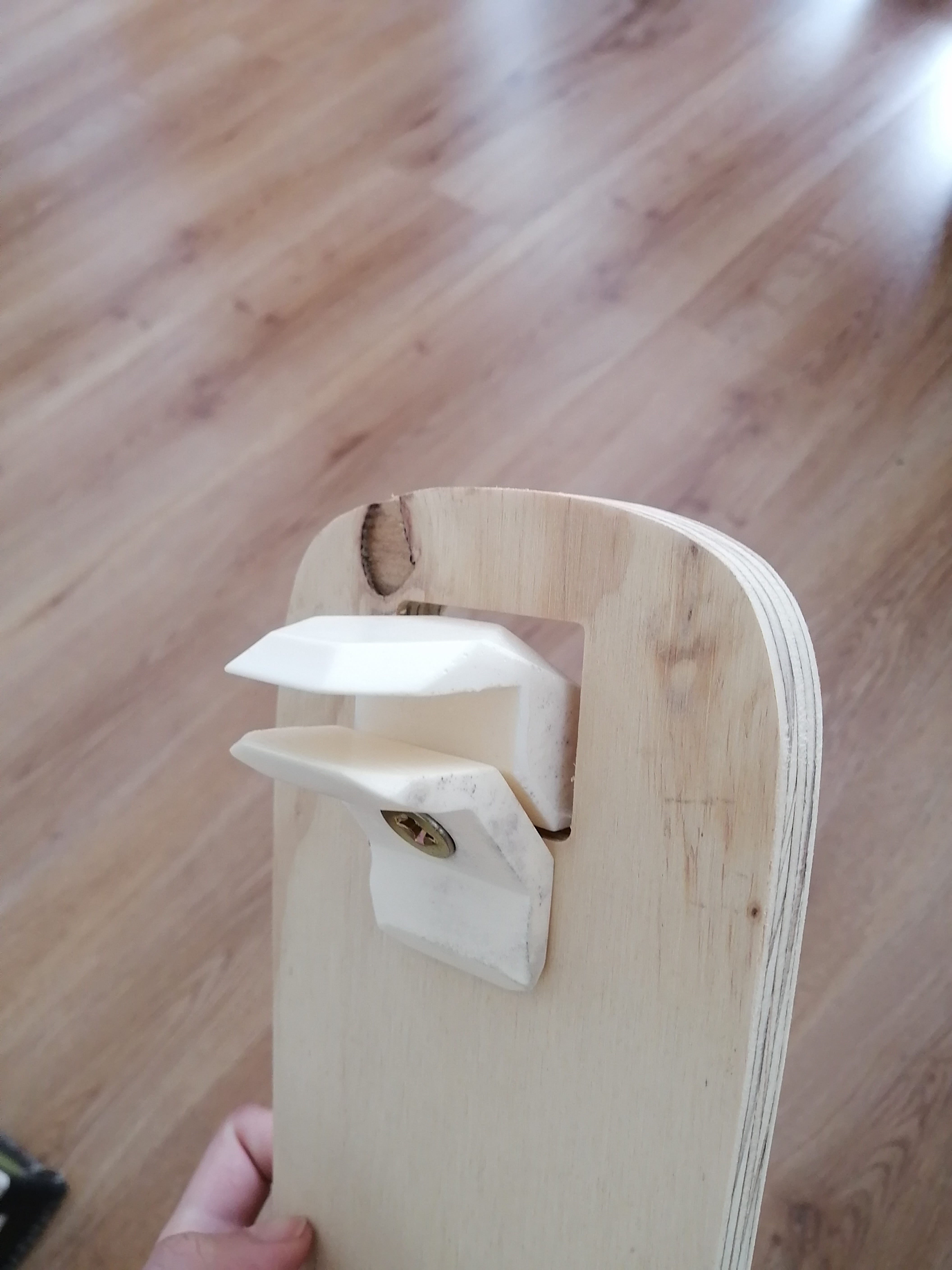
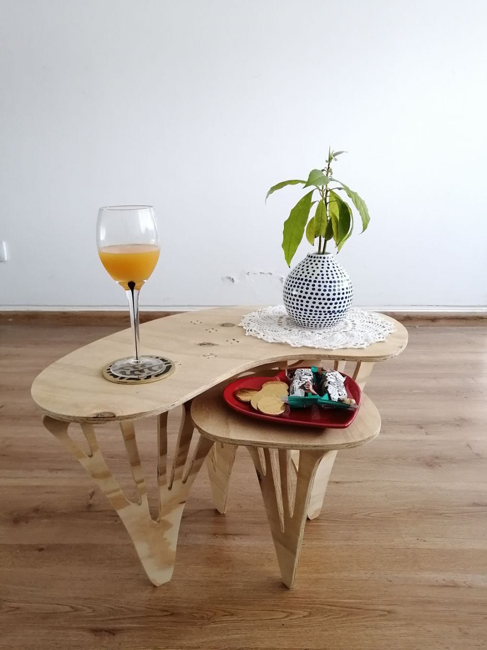
Here is the final assembly of the coffee table, it is very light and easy to assemble!
New coffee table with topology optimization
It was noted in the local review that my new design did not have machined joinery so my Reuleaux triangle coffee table wouldn't pass the assignment checklist, so I’ll be trying a new design this week.
My first design was too heavy to the eye and used too much material (more than an MDF sheet) I'm going to try Topology optimization and applied it to my design process.
First I need to know what is Topology Optimization for structural compliance

There’s a small series of youtube videos by TU Delft on introduction to Topology optimization for designers (so almost to none maths!)
In this video series, there's a link to a topology optimization research group with a bunch of apps for topology optimization, I choose the Interactive 2D TopOpt App for windows.
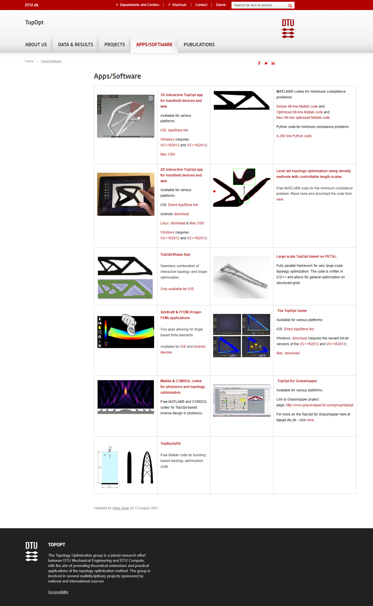
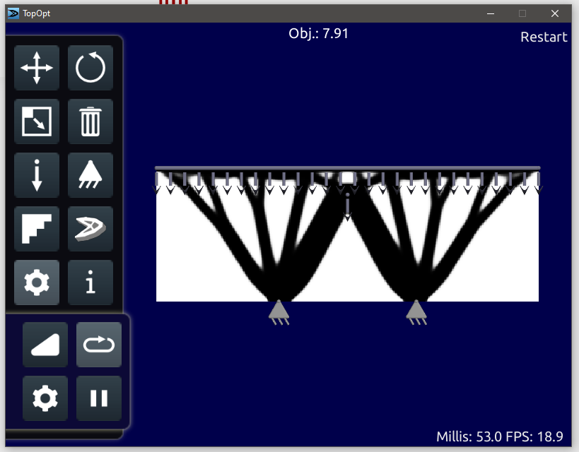
This is like a game where you place the loads and constraints and it models a structure interactively. This works for my design as the black and white resemble a 2D cut.
After playing for a couple of minutes I came up with a design that mimics table legs. The distributed load on top shows where the legs structure meets the tabletop, the two fixed supports are where the legs touch the ground. I added a point load in the middle as this will be the place where a beam will join both legs' structures.
I change the resolution to work on a longer canvas, further tweaking lead me to a design that looks like this:
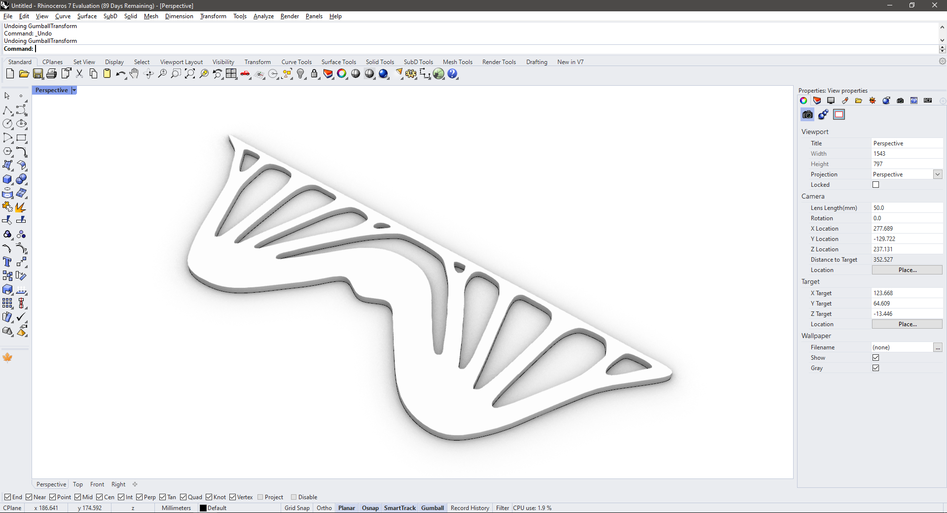
This app has an export to e-mail option for 3D printing, but the option wasn't working…So, just to try I took a screenshot of the shape and imported it to Rhino to have a curve. With some tweaking to smooth the borders and curve optimization, plus extrude and this is the result.

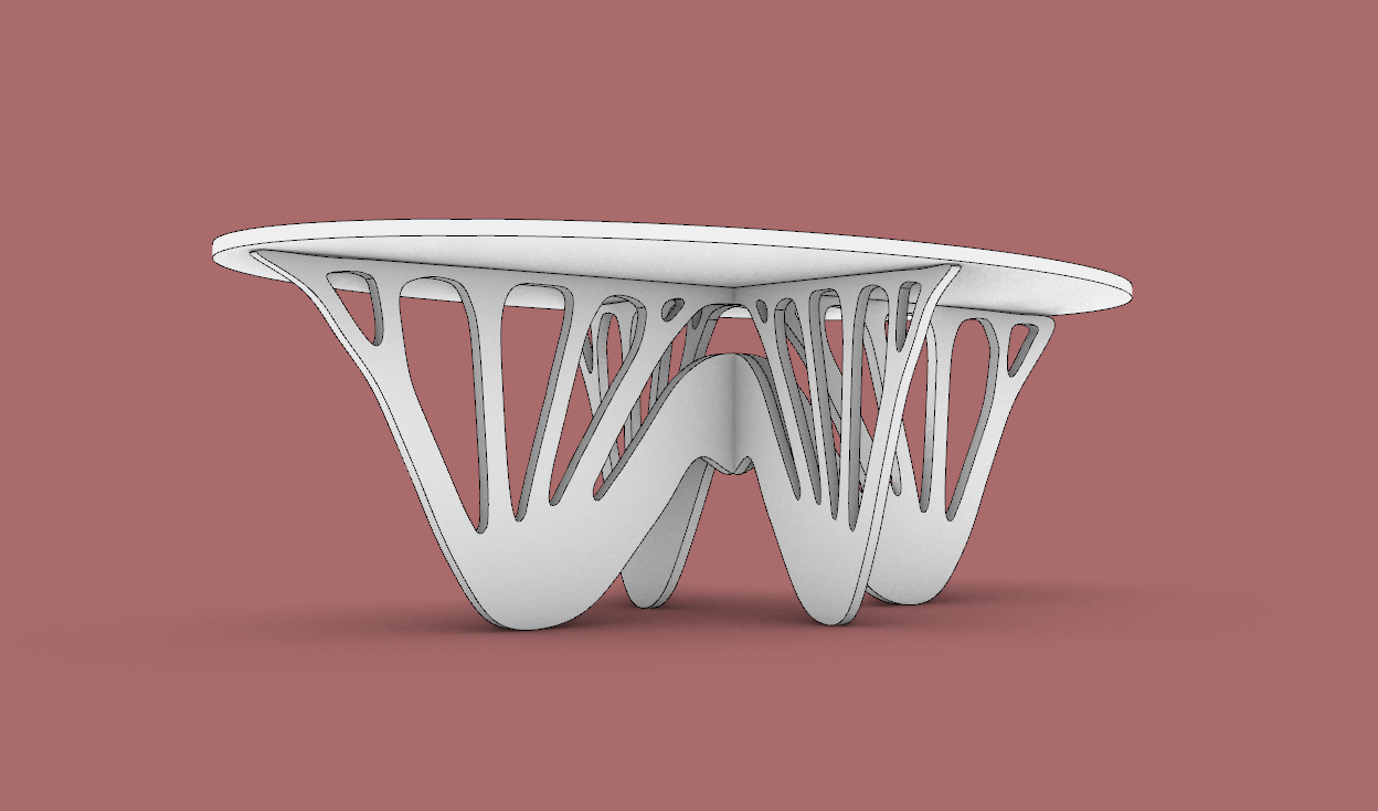
I was not very happy with the result so I made a new design whit two diagrams and follow the same steps above.


With some more tweaks to adjust the pieces to the correct proportions for a coffee table (until this stage I was working unitless), the T bones were placed and cut to fix the tabletop and leg pieces together. The new tabletop has two levels for a dynamic look.
This time the design has a lighter shape and a very art-deco feel.
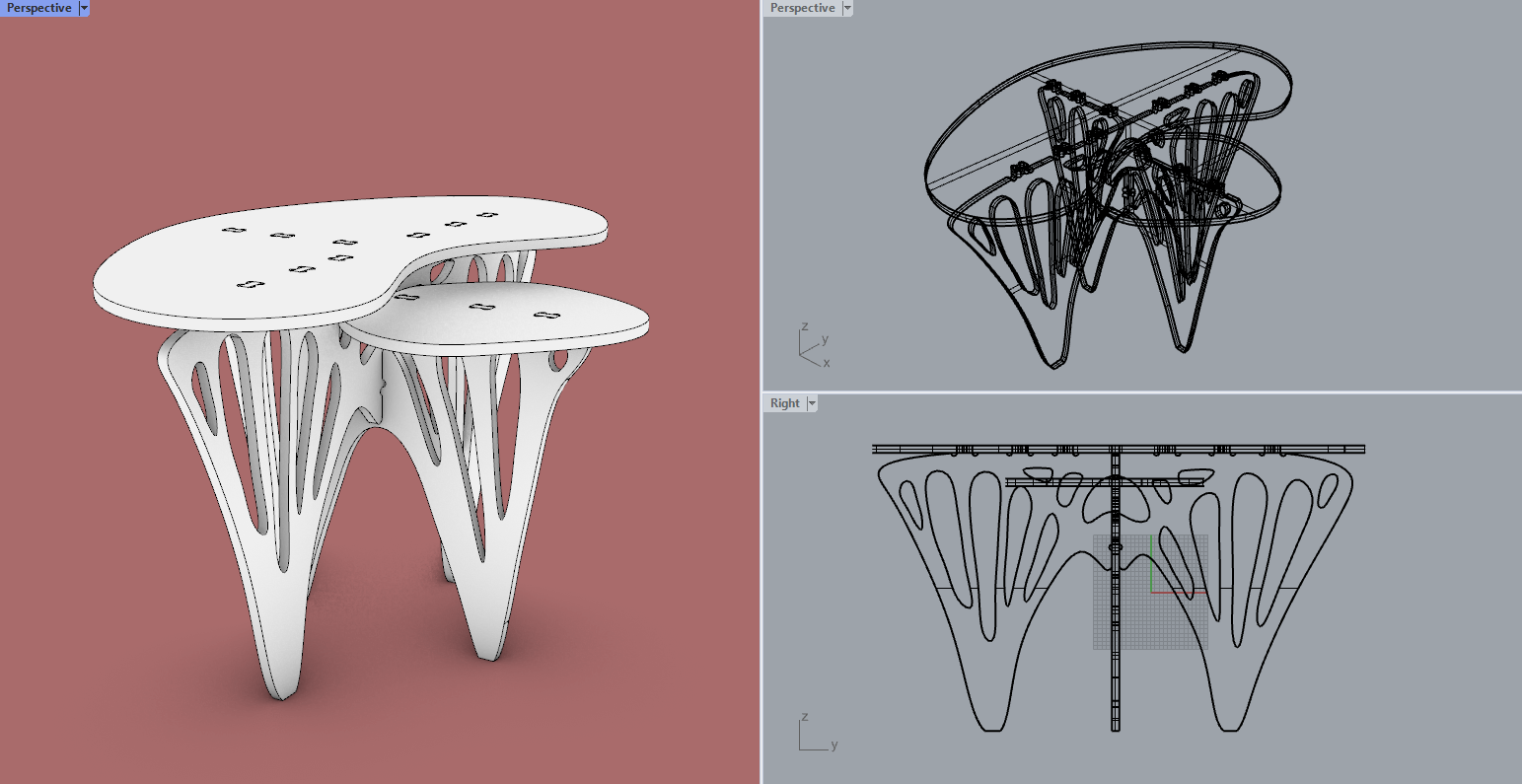
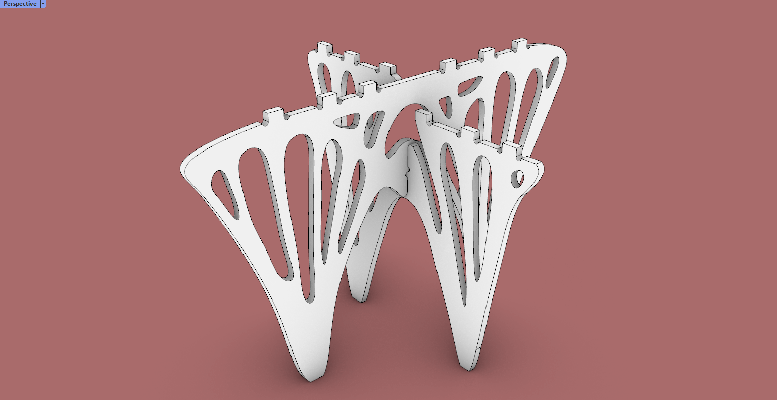
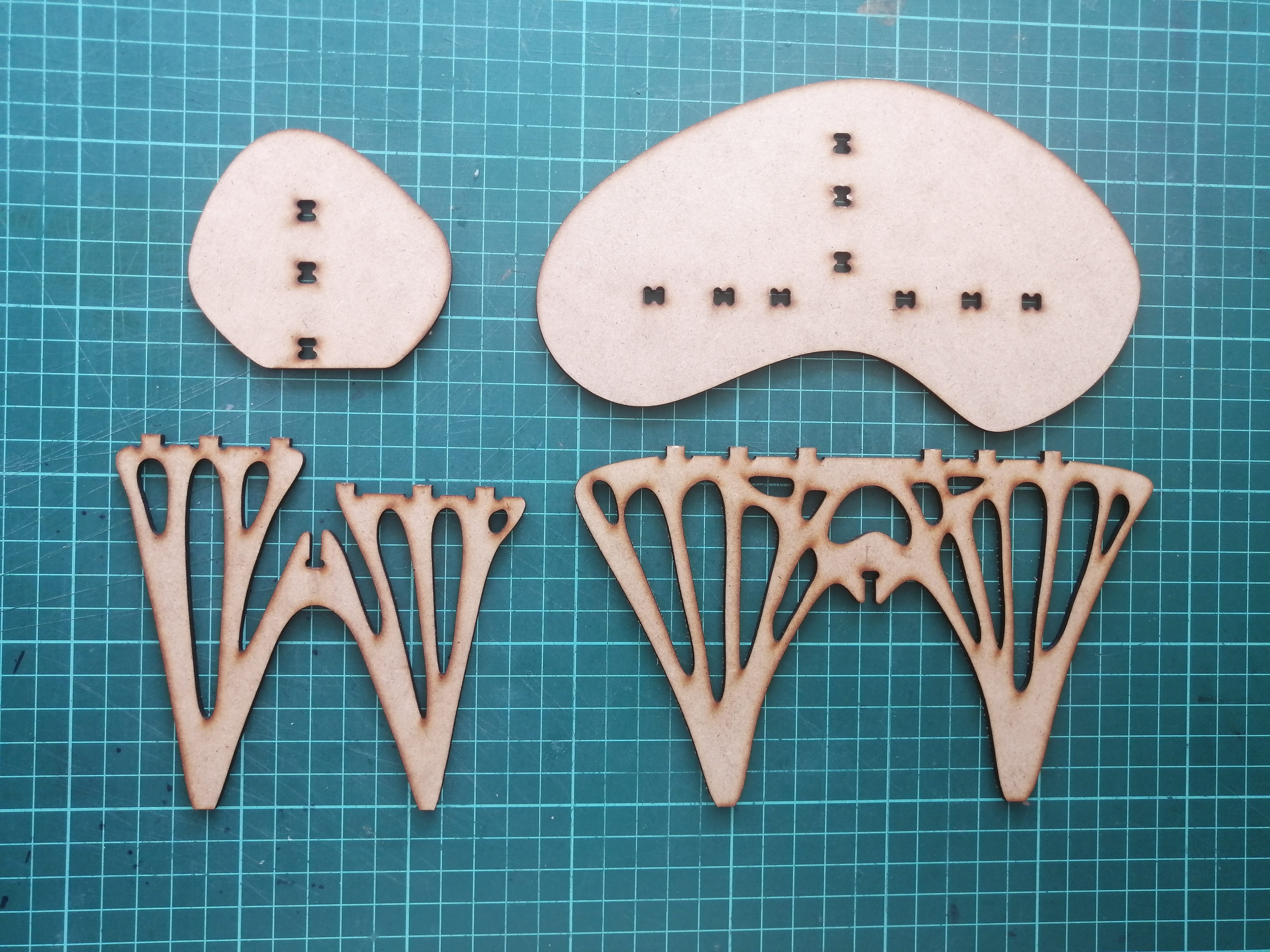
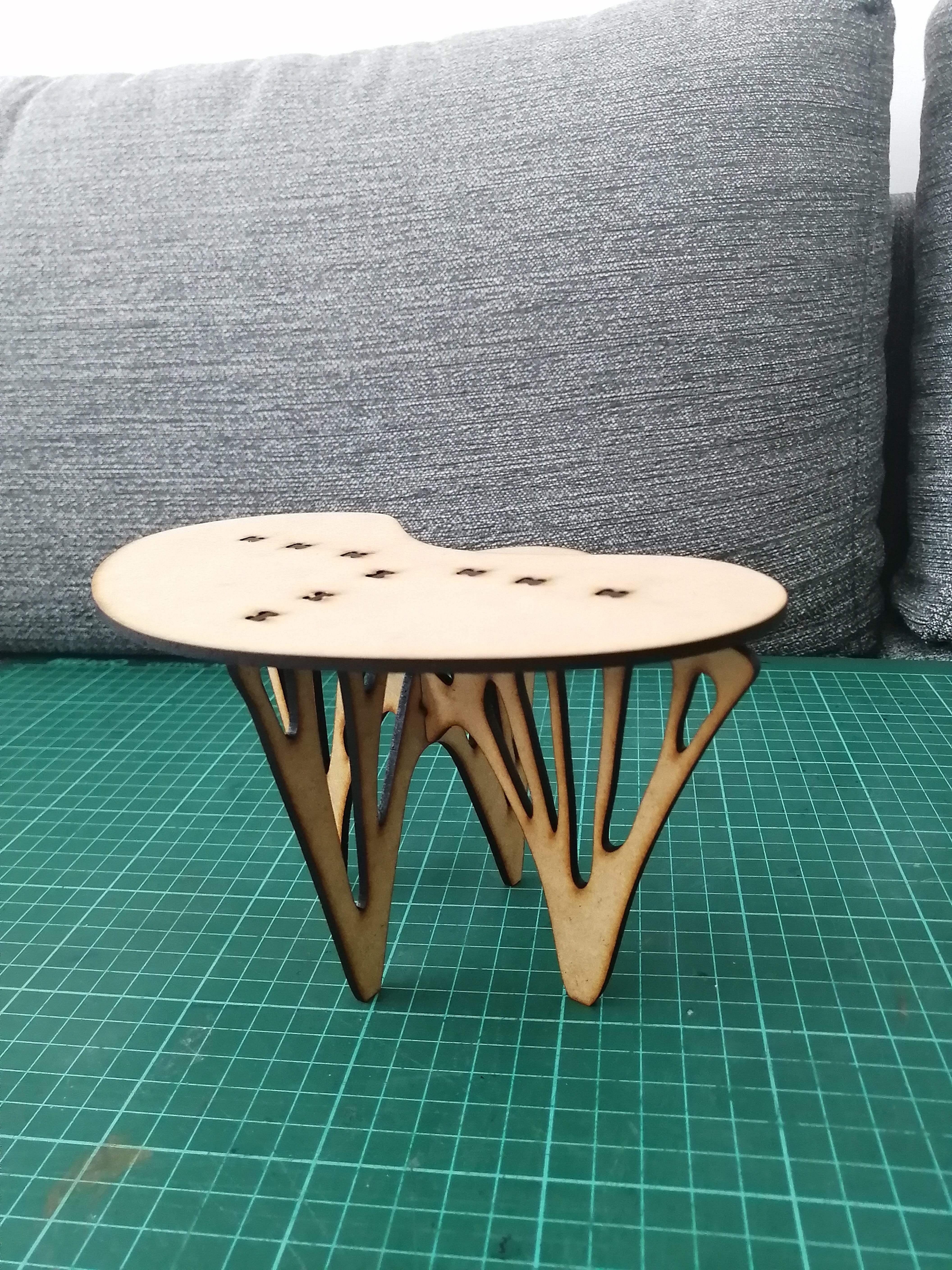
The next step is to fabricate a maquette on a 1/5 scale of the final design, the maquette is fabricated on 3mm MDF, and the final design at full scale will be machined on 15mm MDF.
A few minutes in the laser cutter and the parts are ready to assemble!
The assembly was quick and easy, the maquette feels sturdy and I'm feeling confident that the design will hold well in its final material and scale.
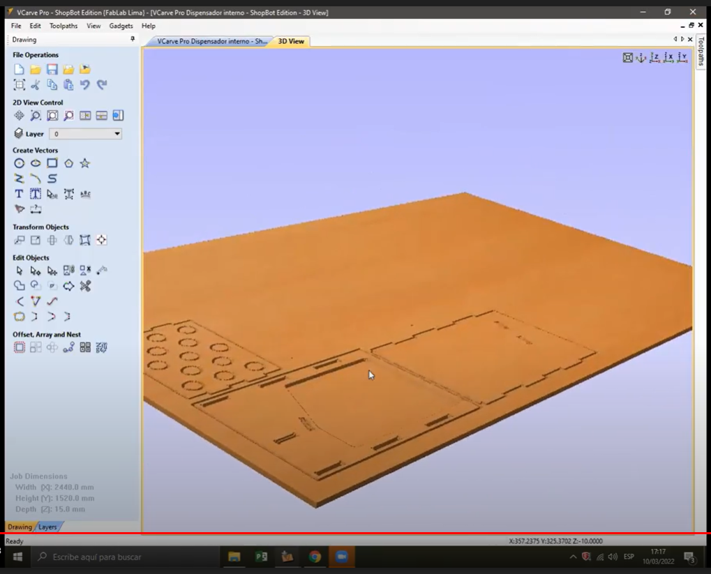
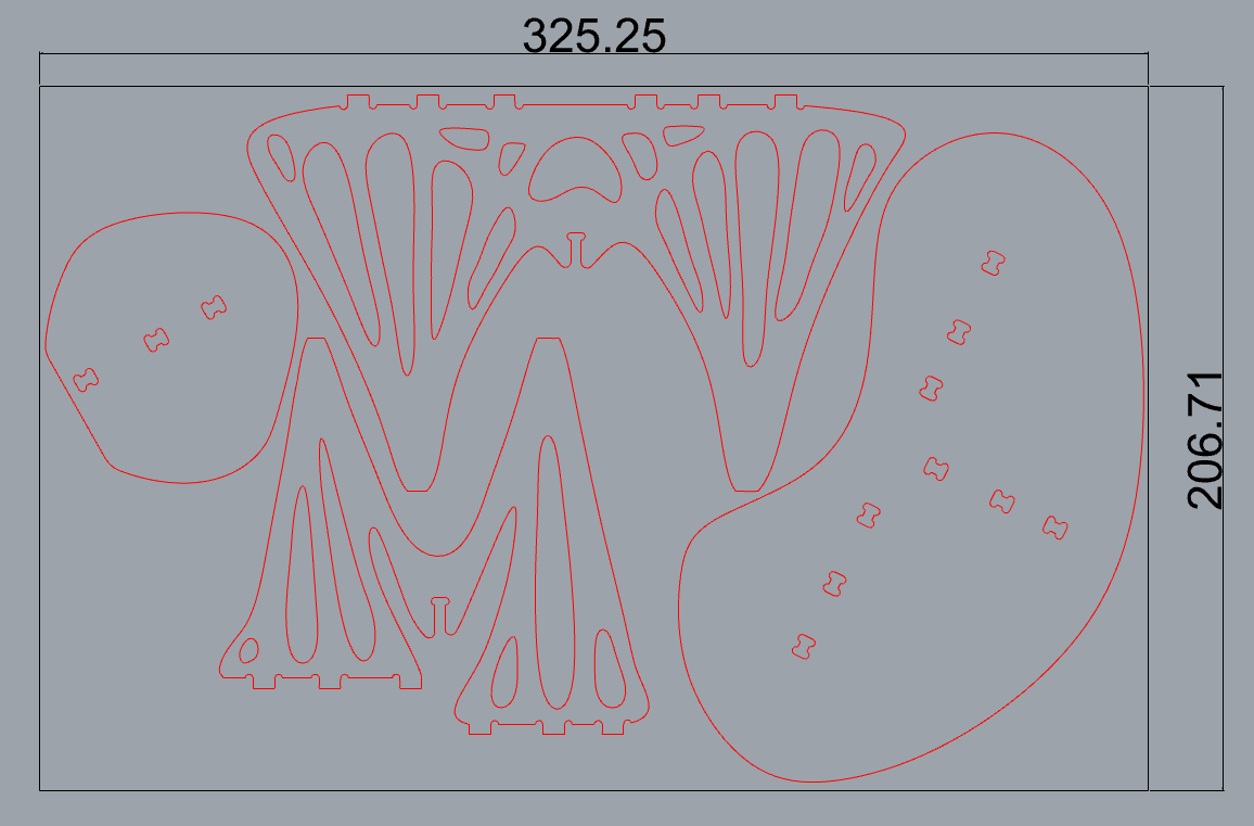
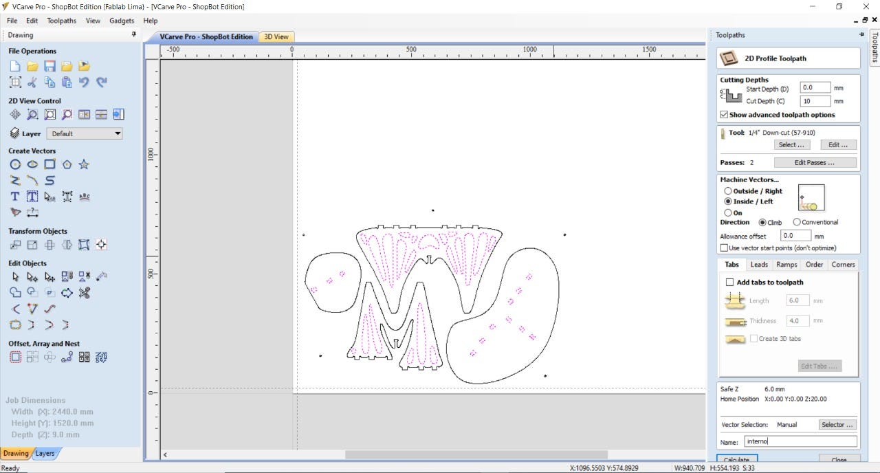
After this quick test, it's time to machine the final product. I used V Carve Pro to make the cut files for the CNC, this time I’ll be working with the ShopBot PRSalpha Machine at FabLab ESAN has a bed size of 1.52 * 2.44m.
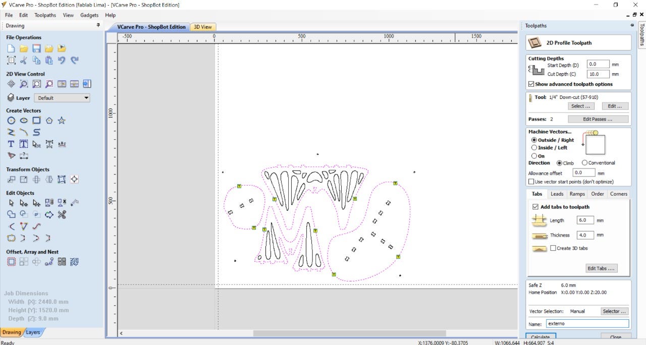
The first step is to set the interior and exterior cuts and set the tabs that will hold the pieces while machining.
I finally picked a 9mm plywood for the final design as this was already available at the lab, so the design would be a 3/5 of the “real” one, but I think that this is more than enough to test machining capabilities.
Settings the tabs:
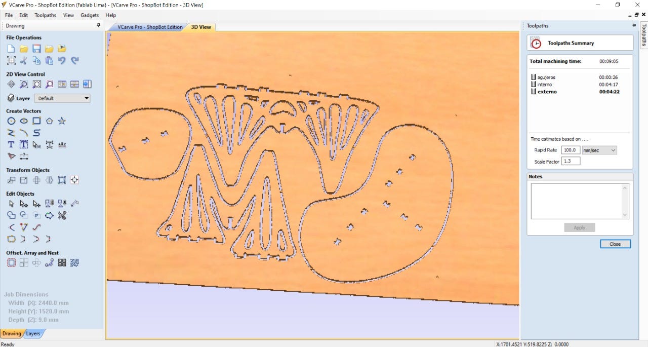
After all the cuts are set we could see a 3D preview of the machining work to be done, and then export the CNC files to the machining software of the Shopbot.
The machining process starts setting the home for the machine, this time is on the bottom right corner of the bed (origin of the material), and next set the Z-axis with an aluminum probe.
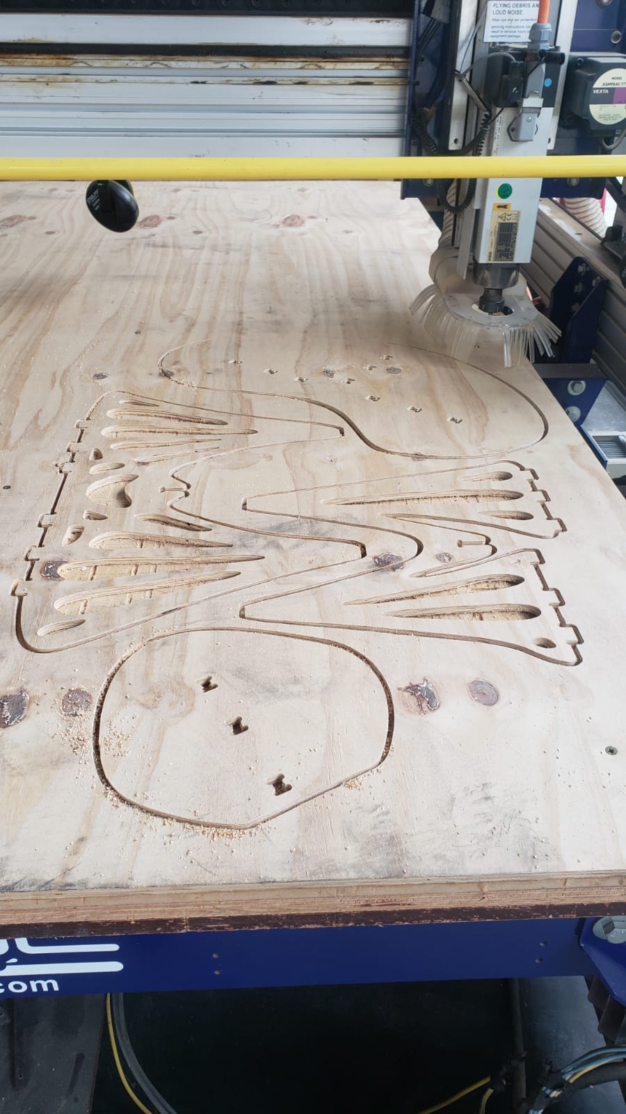
The machining starts by cutting the inside pieces and finishes with the outside perimeters.
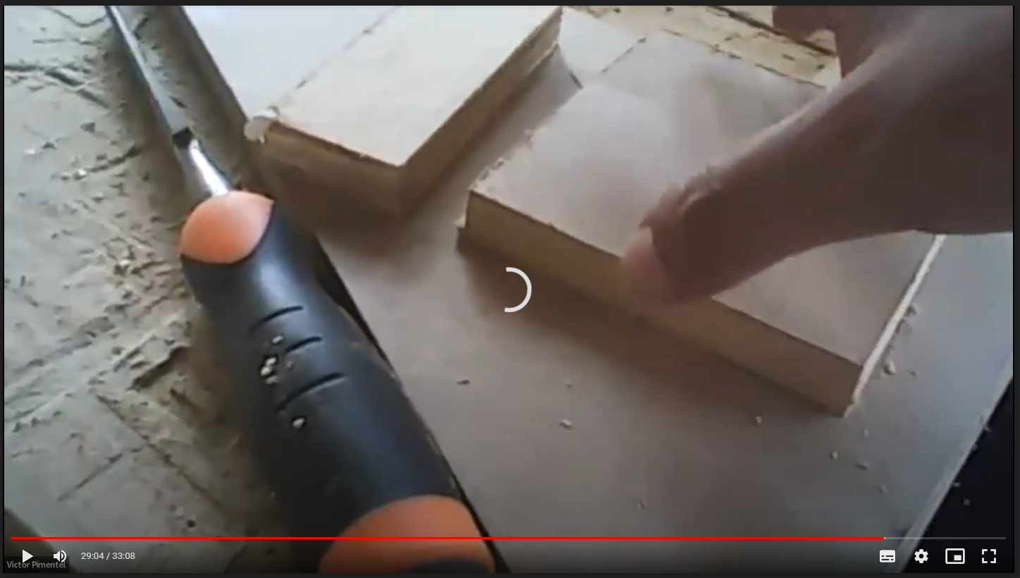
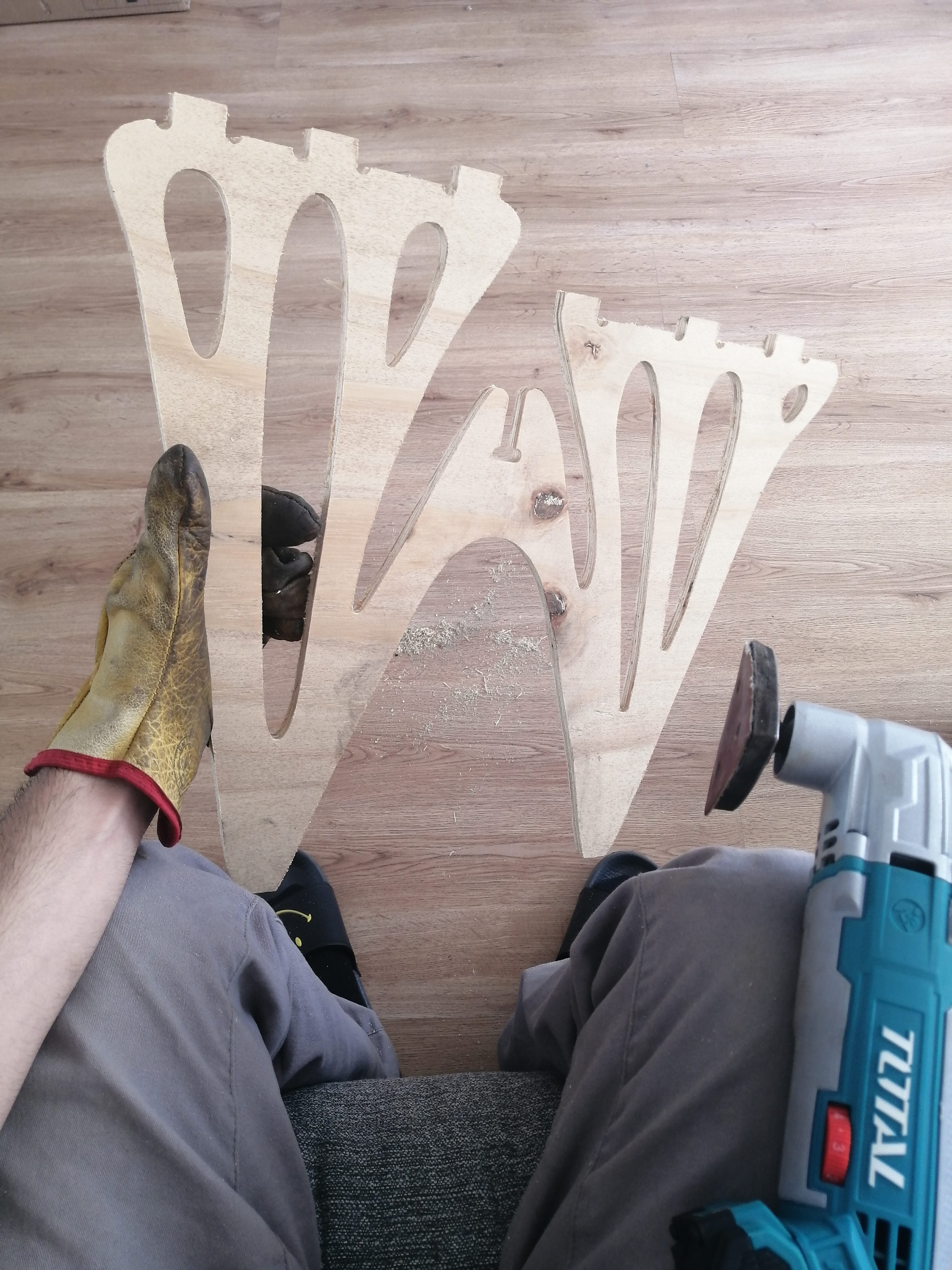
The pieces ready to be liberated for sanding:
The pieces needed considerable sanding to clean the edges because the bottom side of the pieces was very rough, this might be due to the poor quality of the plywood and its thickness (only 9mm).
After an hour or so of sanding, the pieces are ready to be assembled, I noticed another mistake in the machining, the good quality face of the plywood was set facing the bed, so with a down-cut bit, this was the face that got kind of a bad edge finish, while the bad quality face of the plywood facing upwards got a decent finished cut on the edges, whoops!
Pieces ready to assemble!
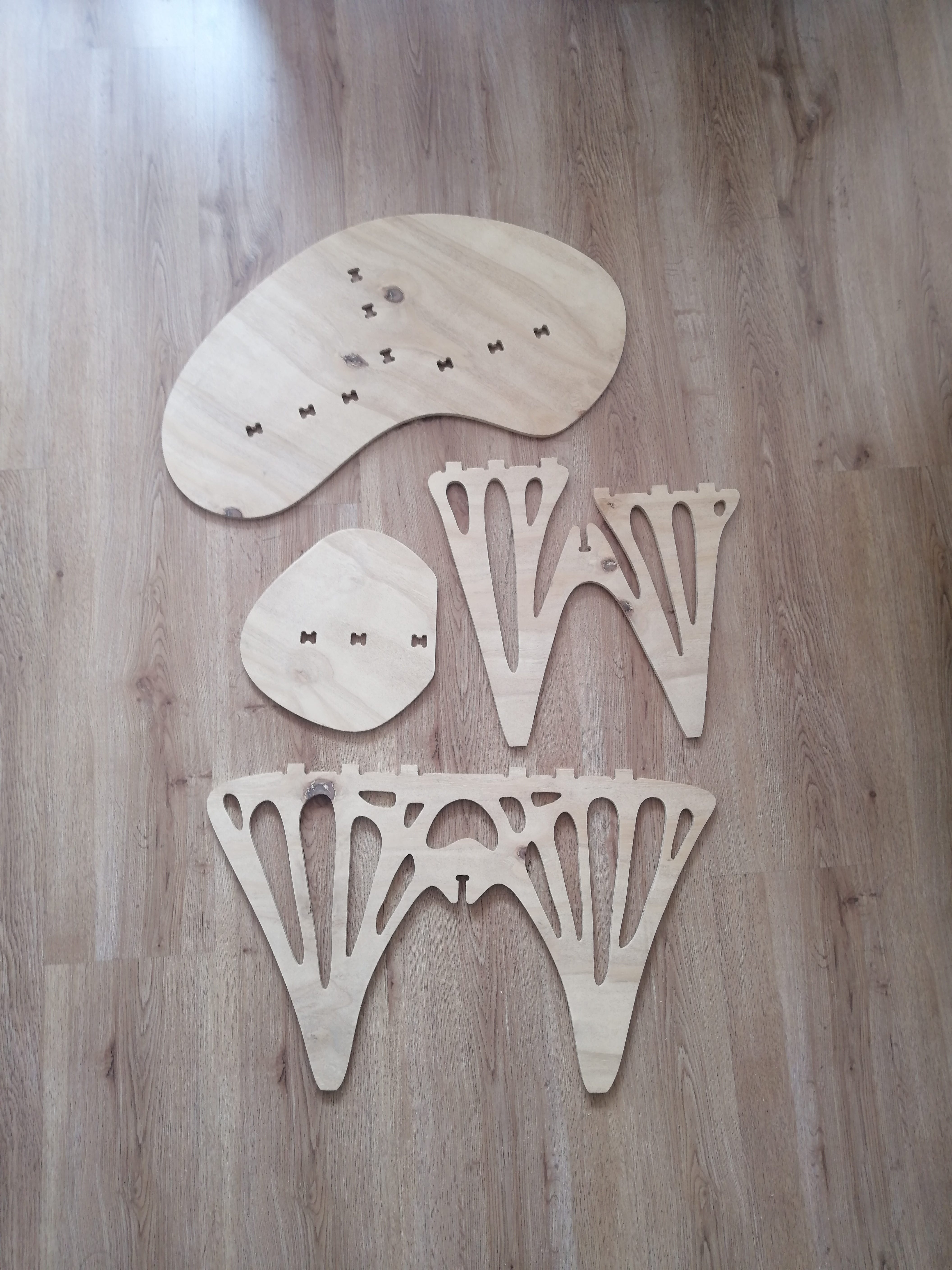
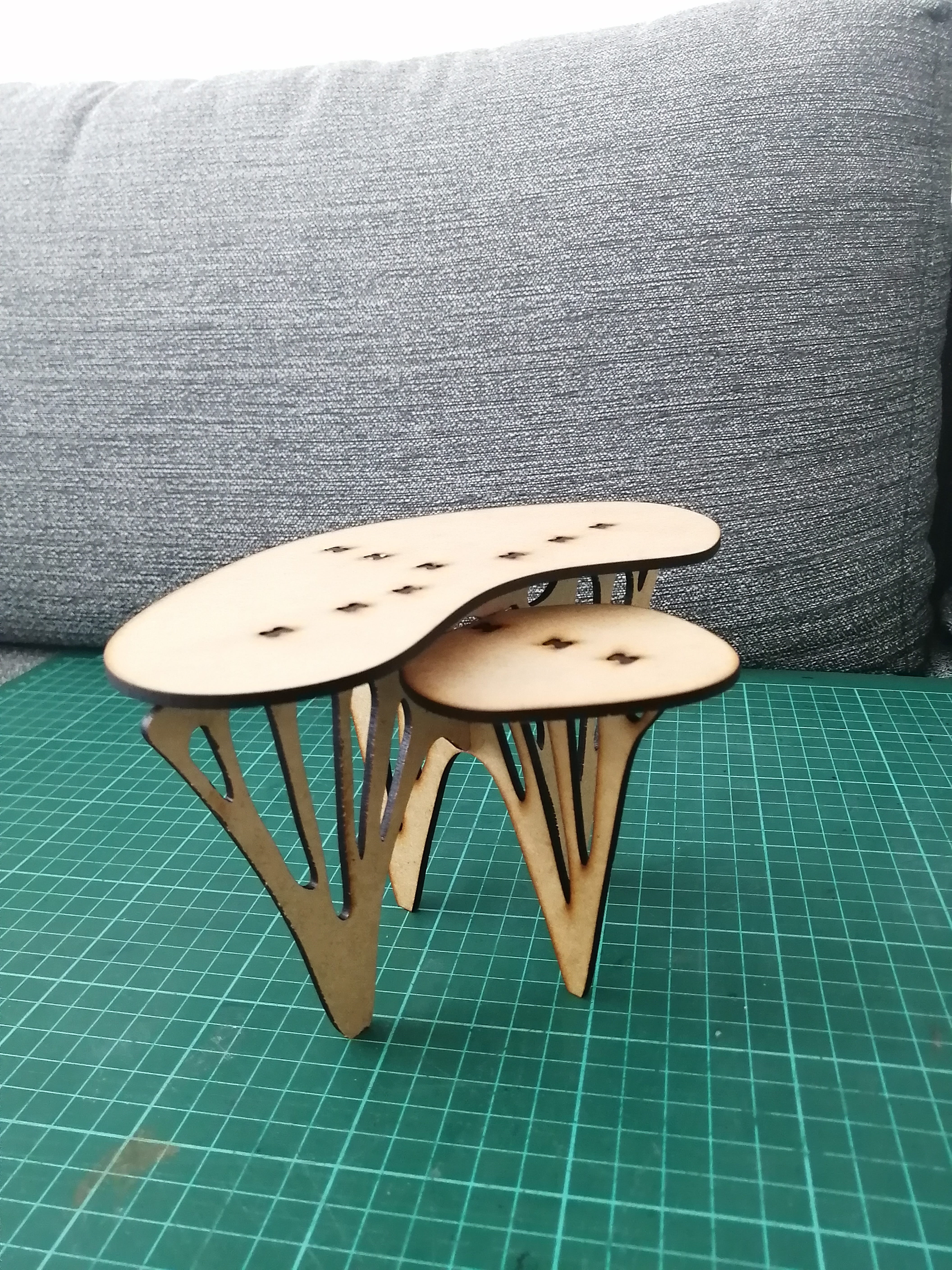
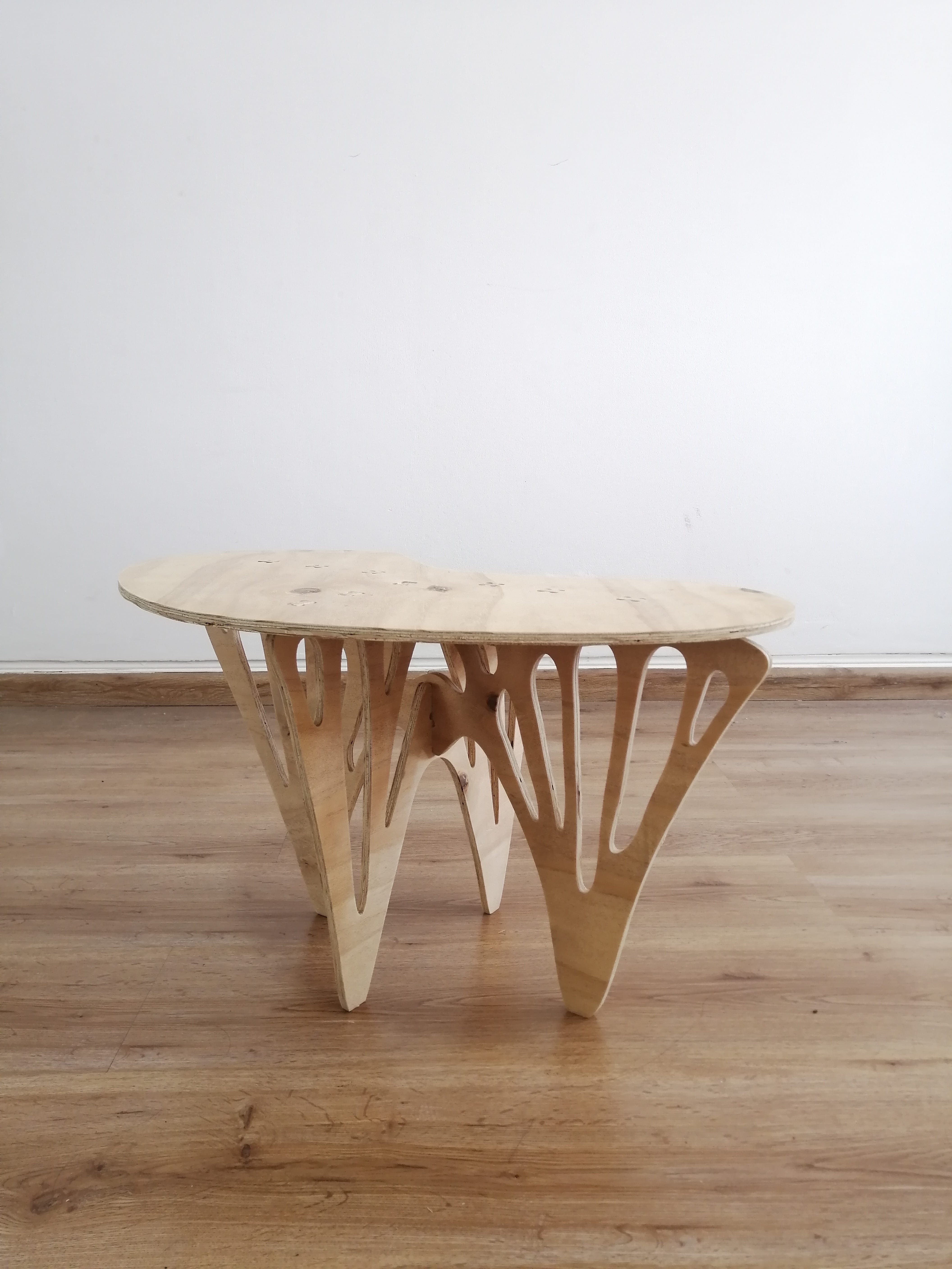
The assembly was tight but at the same time easy, I used a rubber mallet to make the pieces fit together. These are the pics of the finished product!
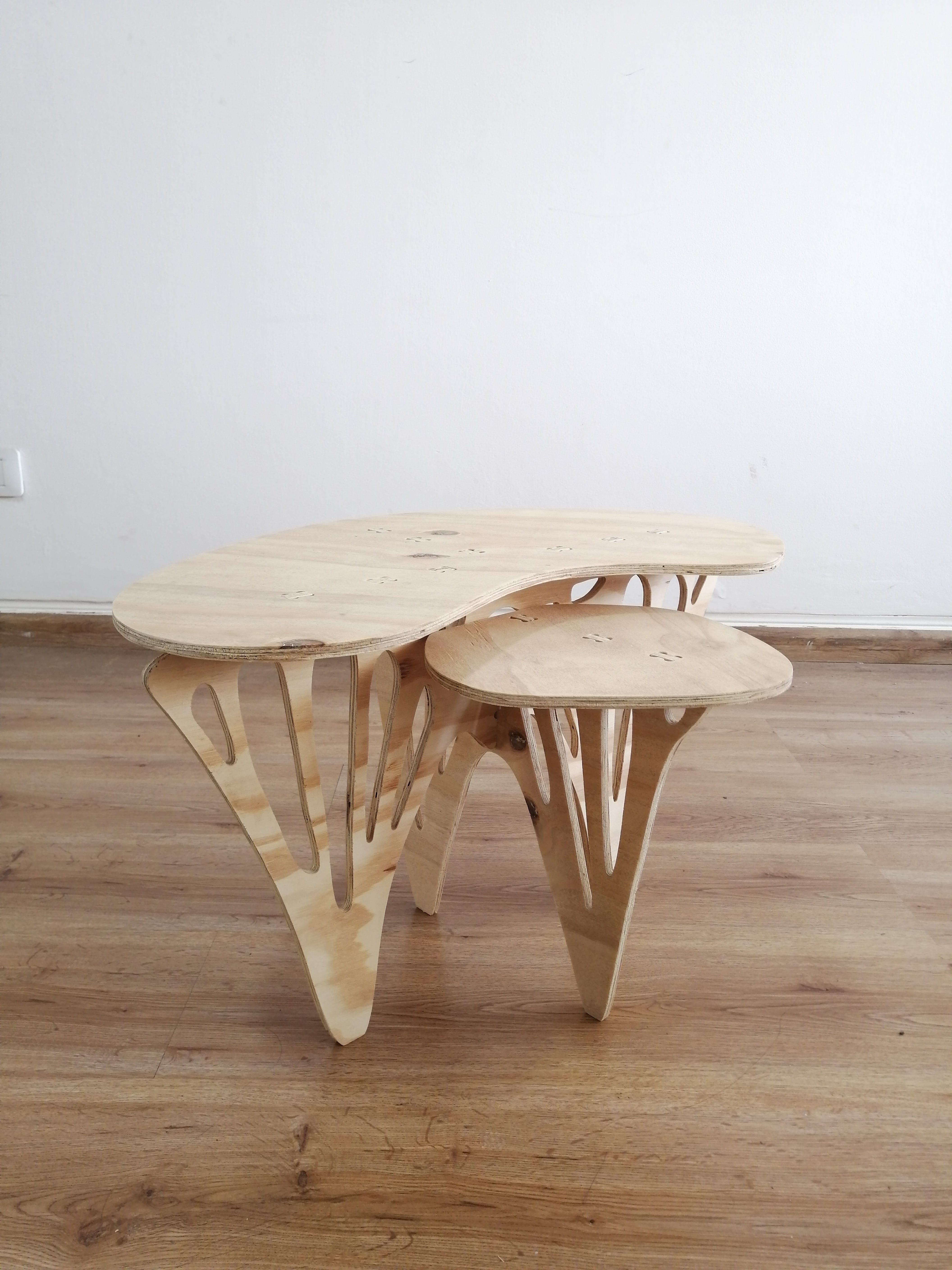

A design flaw that needs to be fixed is that the table is a bit wobbly, this is caused in great measure because of the thickness of the plywood and the lack of lateral rigidity of the structure itself, although this doesn't show on the maquette, I was kind of suspicious that might happen on a bigger prototype.
This would be fixed by adding some joinery to connect the little board on the table to the structure, or by adding another set of transverse legs.
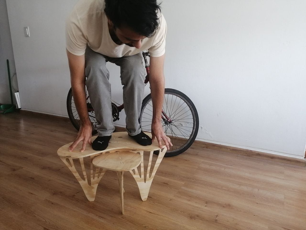
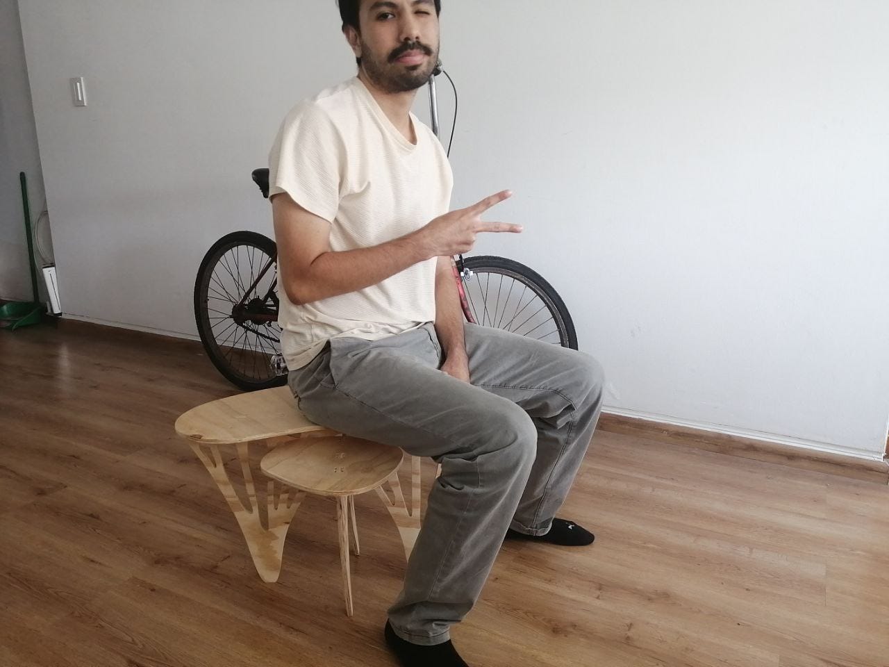
Even though the table is quite sturdy for its size and holds weight (axial loads) very well! taking into account that it's a 3/5 scale of the finished product so, the topology optimization kind of works!
Here I am testing the strength of the table and risking my life for product development:
Download the .dxf file for the Topology Optimized Coffee Table here