Previous:
Download Eagle and install it.
Download the Fab library Fab library components from Gitlab.
Design (Redraw) the Echo board with Eagle
I choose the Echoboard based in the ATtiny44.
Loading the library in Eagle
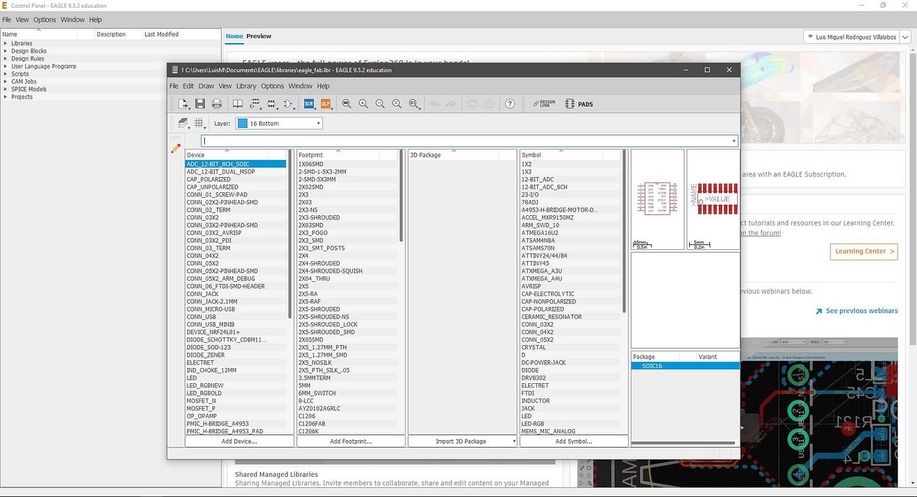
The first window when we start Eagle is a control panel, in this, we choose the option File / Open / Library and select the .lbr file (components library)

The library is a list of the components used in FabAcademy
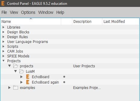
but to use the library, we must open a schematic design from the eagle control panel. I decided to first create a folder with my name and a new project called the Echo board.
Drawing the circuit
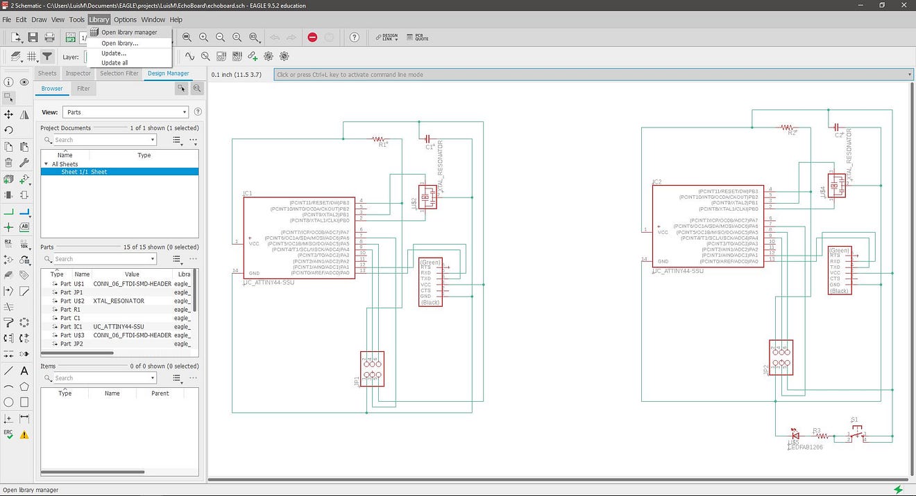
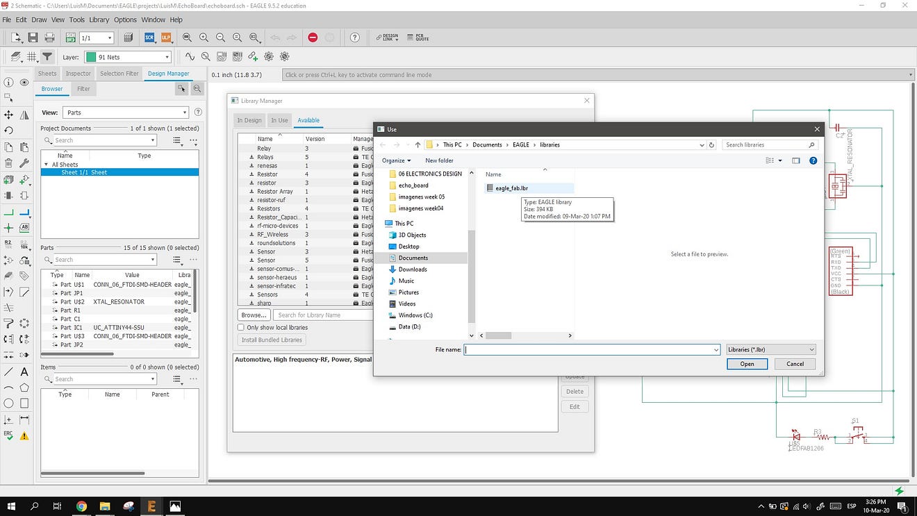
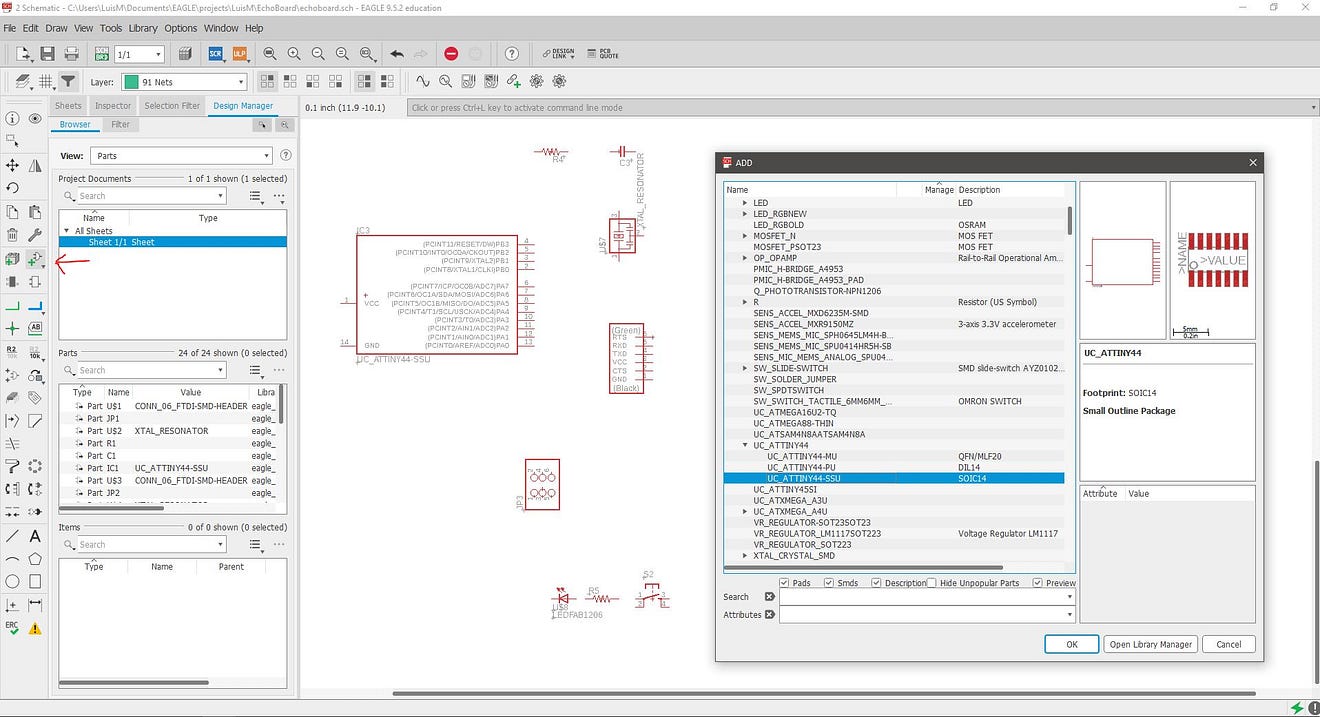
Now, from this project, I created a new schematic file. In this new file, I set the library from the Tab Library / Open library manager. next, select the tab available and click on the browse button, to find the directory of our library, select it and the library we’ll be ready to use.
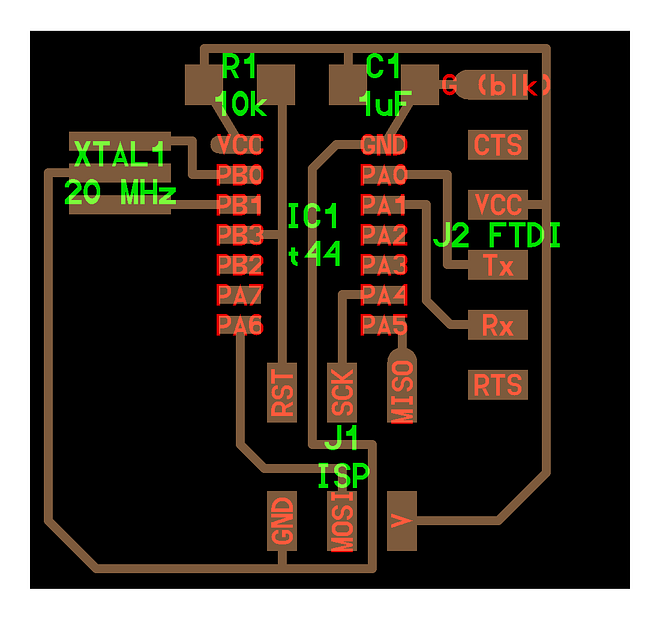
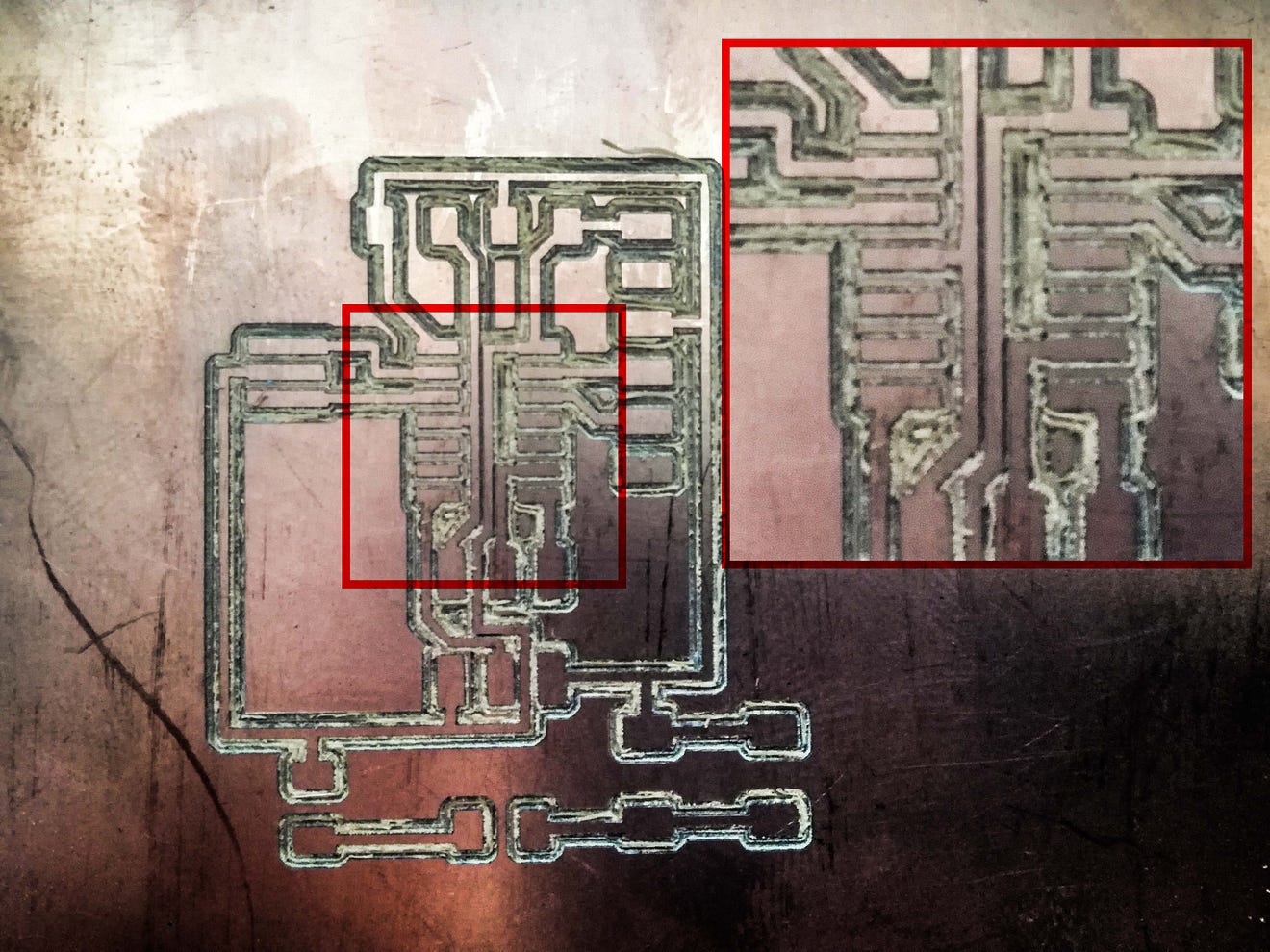
In this working space, we need to select the components for our echo board, using the first image as a guide, so the components are:
- ATtiny 44
- Resistor 10k
- Capacitor 1uF
- Resonator 20Mhz
- 6x1 FTDI
- 2x3 ISP
And the components to add for the assignment:
- Resistor 1k
- 1 LED
- 1 Button
The workflow is to use the button Add Part to set all the components from the Fab Library, and positioning more or less in the place these will end up in the PCB.
Once we have all the components, start making the connections using the Net tool. This creates green lines between the components. we can also use the Show button to inspect if these lines are connected. I started doing the GND and VCC lines first.
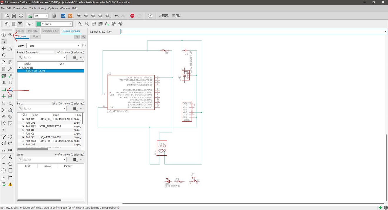
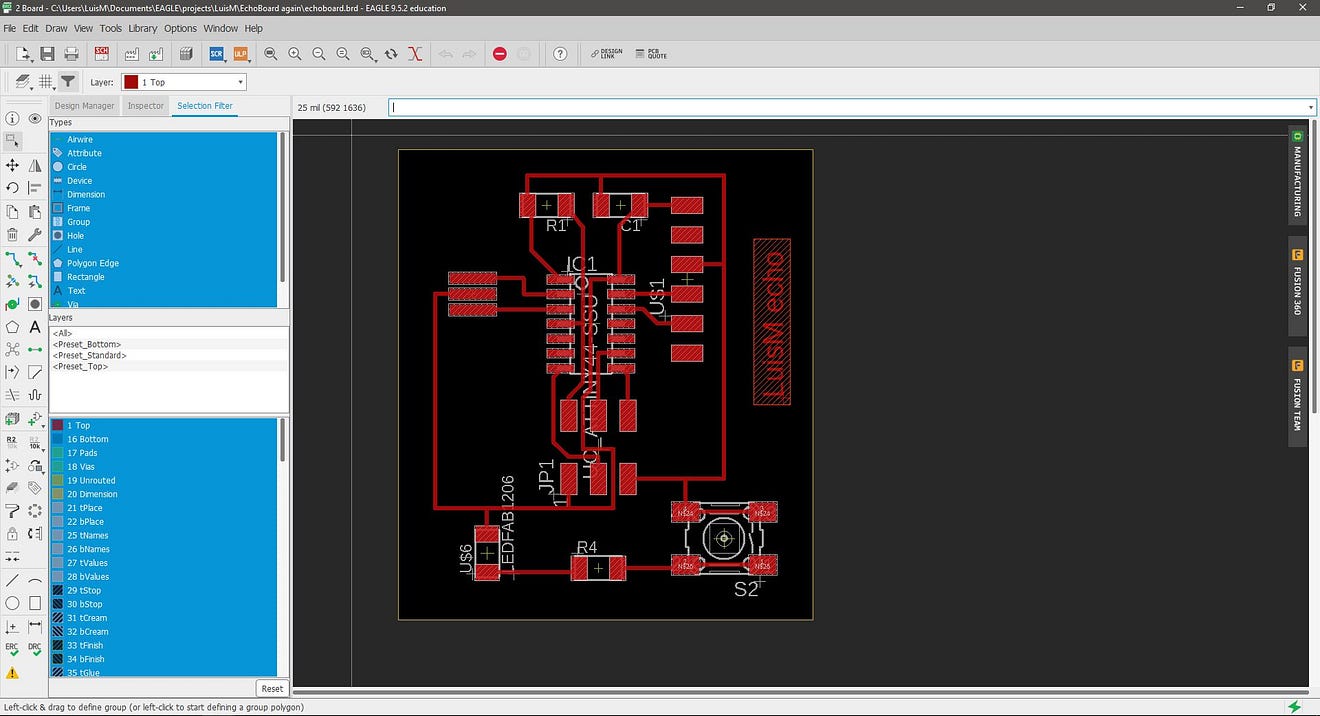
After all the connections are made. Change to the PCB view with the Generate / Switch to board button

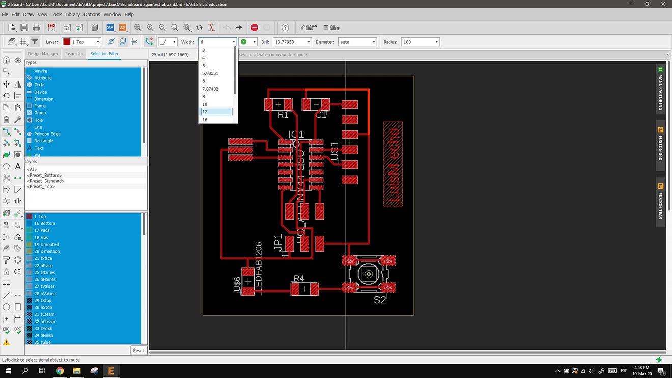
In the PCB view, I used the Route Airwire button to make the traces. To draw the trace wider I modify the parameter from 6 to 12
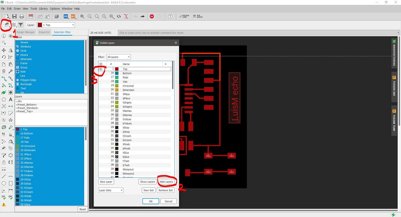
To export the circuit as an image first, we need to configure the layers to show only the traces and pads.
With the Layer button, press the hide layers and then click on the Top layer button to only show the RED layer.
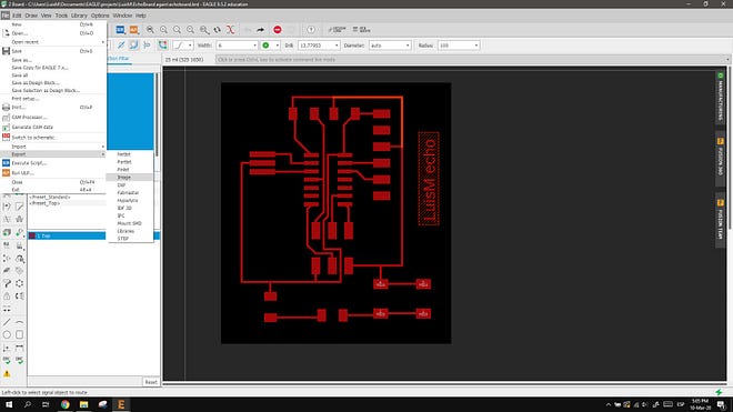
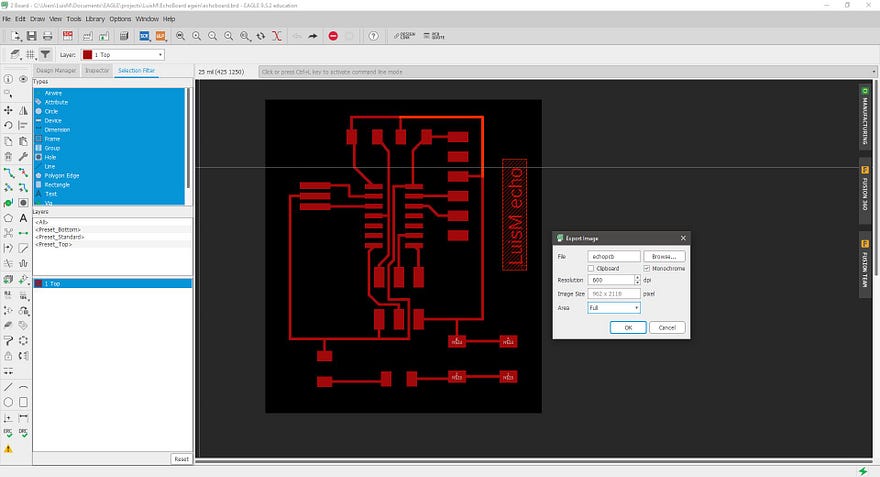
Next, I used the File / Export / Image and select a monochrome export with 600 dpi.
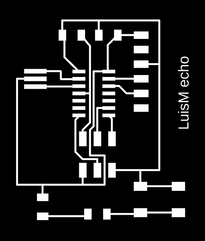
I used Photoshop software to make a custom cutout image file. The final .png files look like this: (the cutout image must be color inverted, but I noticed it too late)
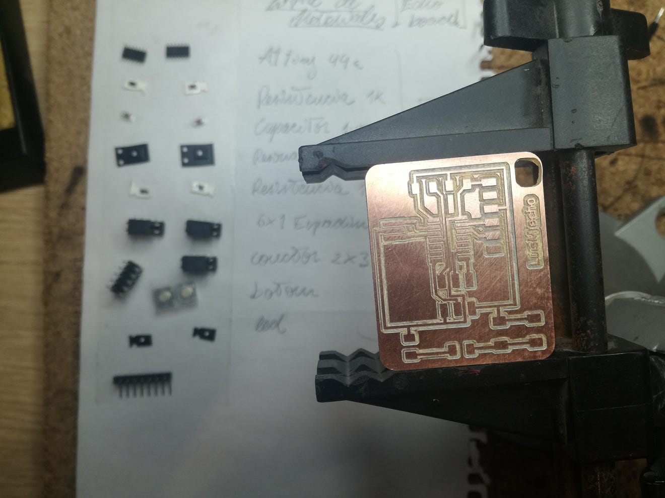
Milling the board
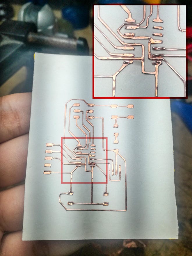
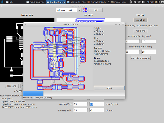
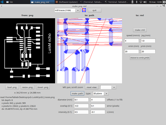
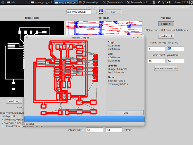
I used the same procedure as the Electronics Production Assignment and milled the board using the Roland Modela. First the traces file.
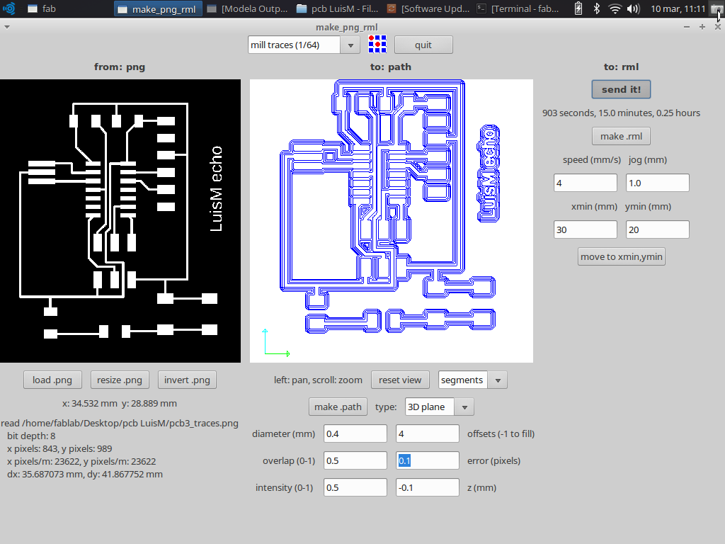
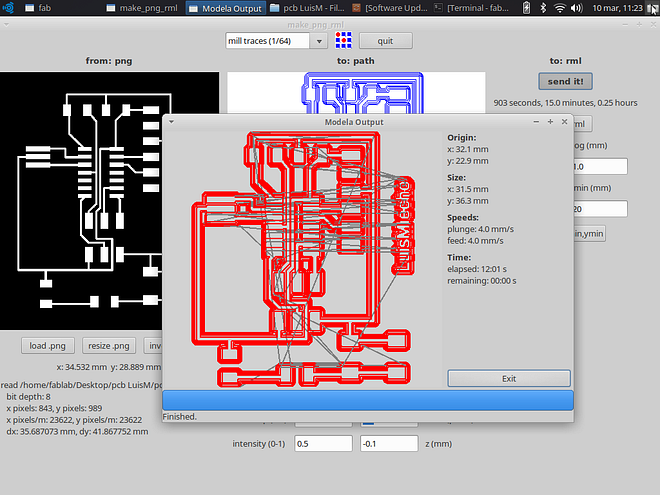
The traces milling took 12 minutes to complete
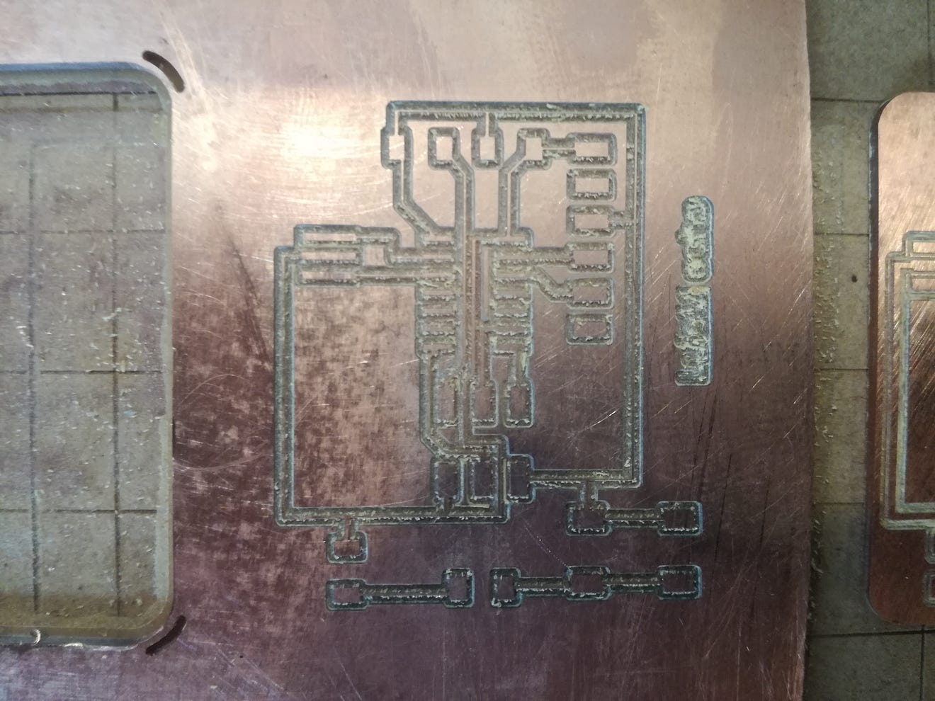
The milling result after a light sanding.

Next, I uploaded the cutout file and worked with the 1/32 milling bit. This work took 3 minutes and 20 seconds.
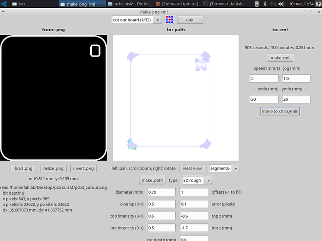
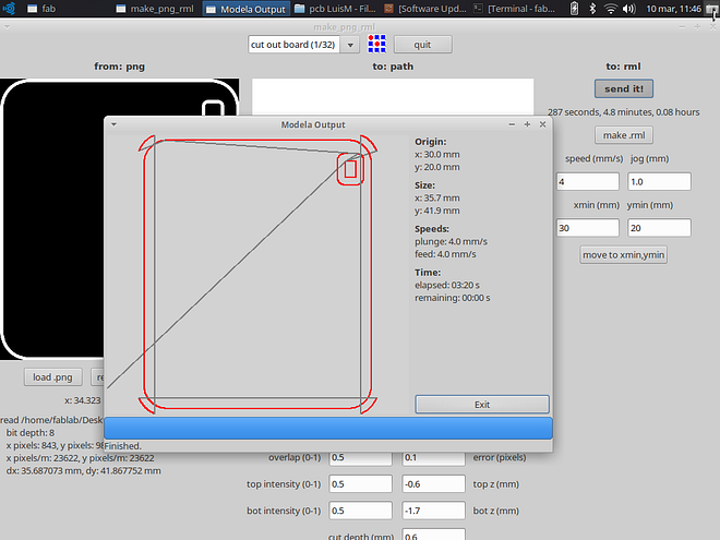
Notice that I generated a wrong color code for the cutout, I should have inverted the .png image before generating the cutting path. Anyway, the cutout worked but left the hole too close to the edge.
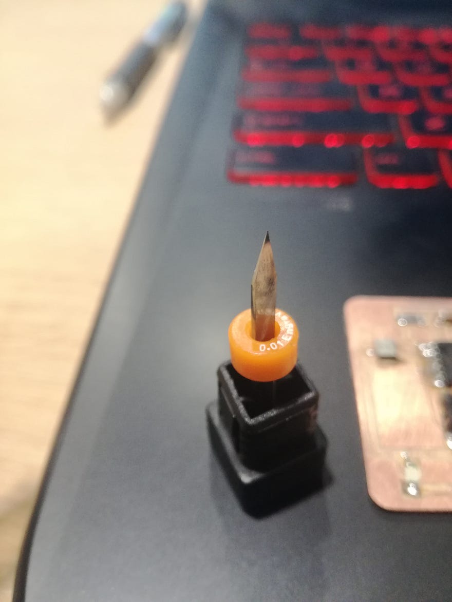
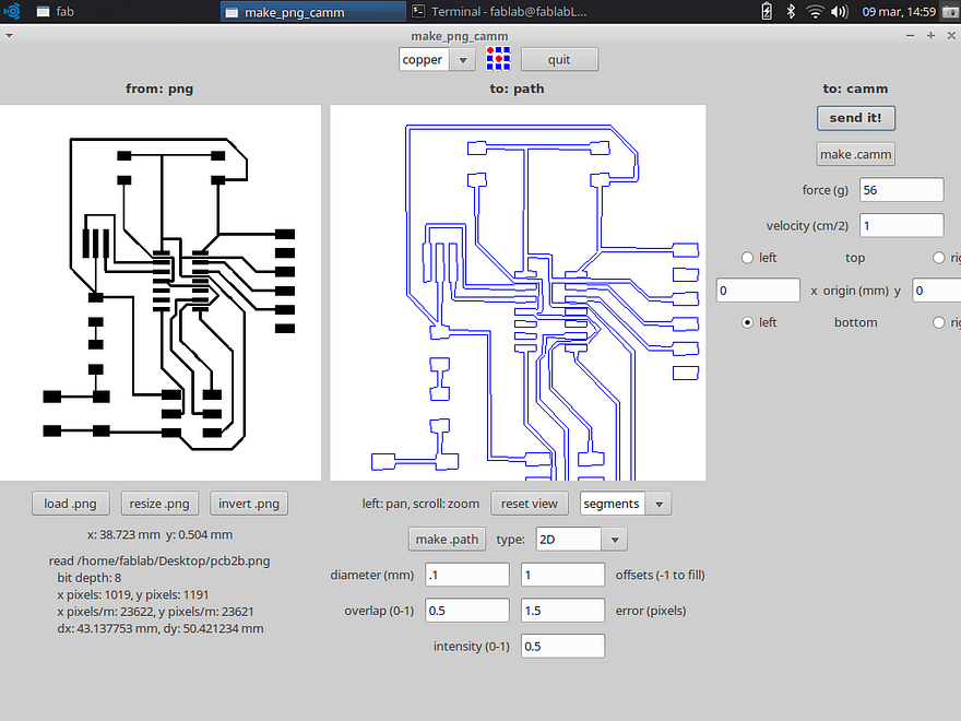
Some notes: This time I was using a spade type milling bit because the classic 1/64 broke (my fault!). This new bit is 0.01, but the instructor suggested that I should use the 1/64 milling parameters to test it. The milling came out ok, but some of the cuts were not clean, leaving a lot of residue from the board in the form of little strings. Also, in the finner traces (between the pads of the ATtiny) the copper was not completely removed.
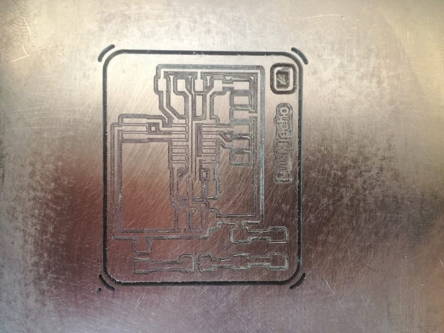
I did some more tests changing the parameters like the diameter of the tool, number of offsets and overlapping, but more testing is required. In this second test, the copper between the pads was completely removed, but the traces came too thin. notice how the name on the right was removed.
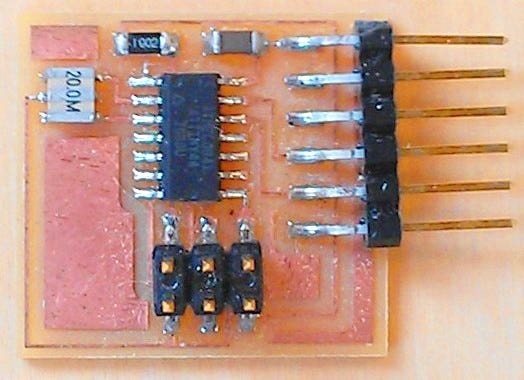
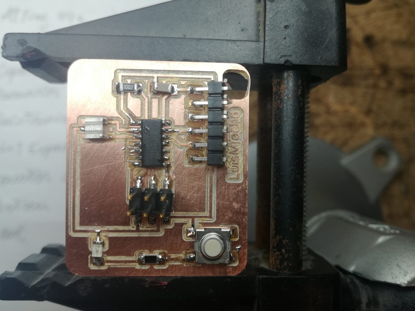
Soldering components
This is the board with the components ready for soldering. For this step, I used the same procedure of Electronics Production Assignment . Upon closer inspection, the board did not have any touching traces, only those copper parts between the pads that will prove to be a pain when soldering.
I started with the ATtiny, this is by far the hardest component, notice how on some spots the solder attached to those tiny parts of copper between the pads, this caused little short-circuits and I tried my best to remove them with copper braid (this made it worse) and later using only the tip of the solder.
I was also having some issues with the temperature of the tip, some spots on the board would burn almost instantly (leaving brown spots) and some others did not heat and cause cold soldering. This is the final board:
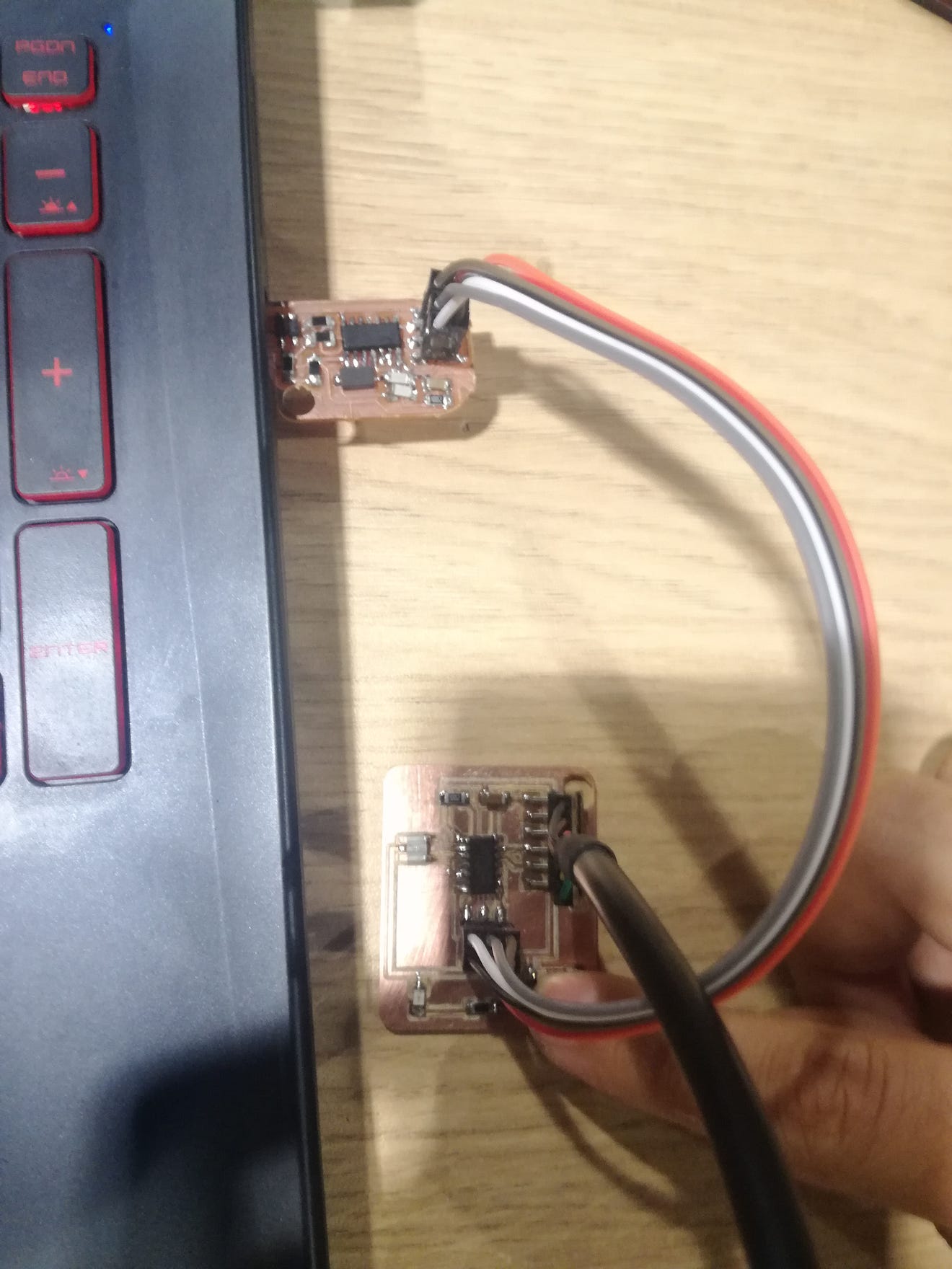
Programming
I download all the files and placed them in a folder called “echo”. From this directory, I open a terminal and check if the machine was detecting the connected ISP and FTDI using the lsusb command.
I then proceed to access the commands as shown in the programming sheet
The process went smoothly, and all commands worked as it should.
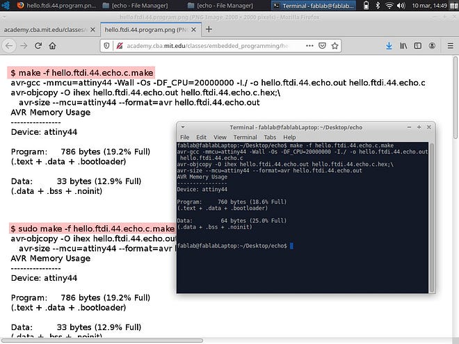
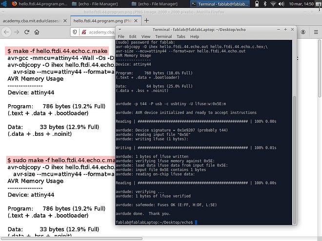
The program uploaded successfully, but the problem came opening the term.py. at first, it wouldn’t even open because it was not installed (duh!).
Later it open but I could not get a response from the board.
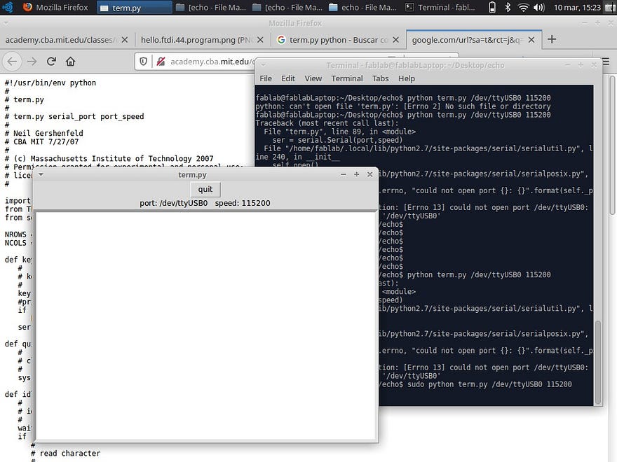
We (the instructor and I), tested several methods, including using Mods like in the video but the FTDI connection would not open, we also tried installing a windows serial terminal but this didn’t work either. Some troubleshooting needs to be done.
Next thing we trying is changing the FTDI cable (we only had one in the FabLab). If this does not work, I’ll be reloading the program or trying Arduino IDE to upload one.
Finally, the blinking LED does work with the button, but only because is directly connected to VCC and GND so it’s not a programable LED.
Download the Eagle files for my echo board:
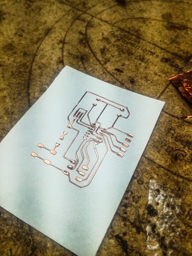
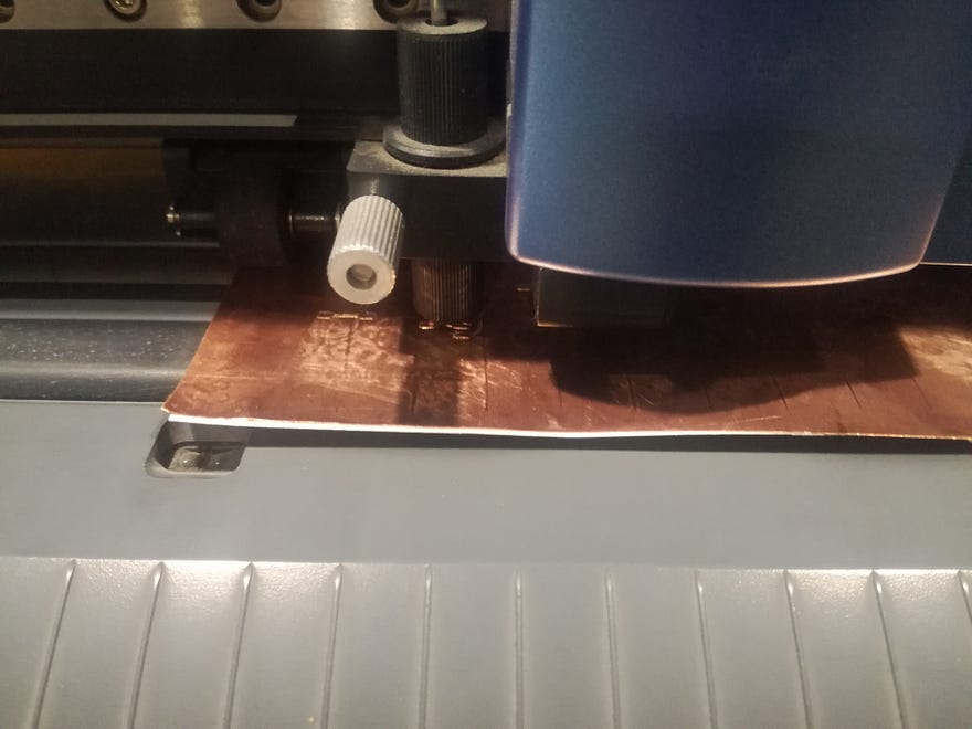
Bonus: I did a test with the vinyl cutter using the same parameters I previously tested in electronics production week.
The result looks very promising, all the traces were cut and the weeding process was quite easy.

But as I learned in the previous assignment, the support material is not the best, so the fine traces tend to move easily and could have some shorts.
Also as this was actually my first test, and the circuit was generated by auto-routing the traces in Eagle, several of these traces were placed between pads, making very difficult weeding (and welding) spots, and left tighter gaps.