16. Interface and application programming
This week I learnt to make a visual interface in Processing for controlling LED colours.
Group Assignment
- Compare as many tool options as possible
Individual Assignment
- Write an application that interfaces a user with an input and/or output device that you made
Hero shot of the week
Group Assignment
Processing interface
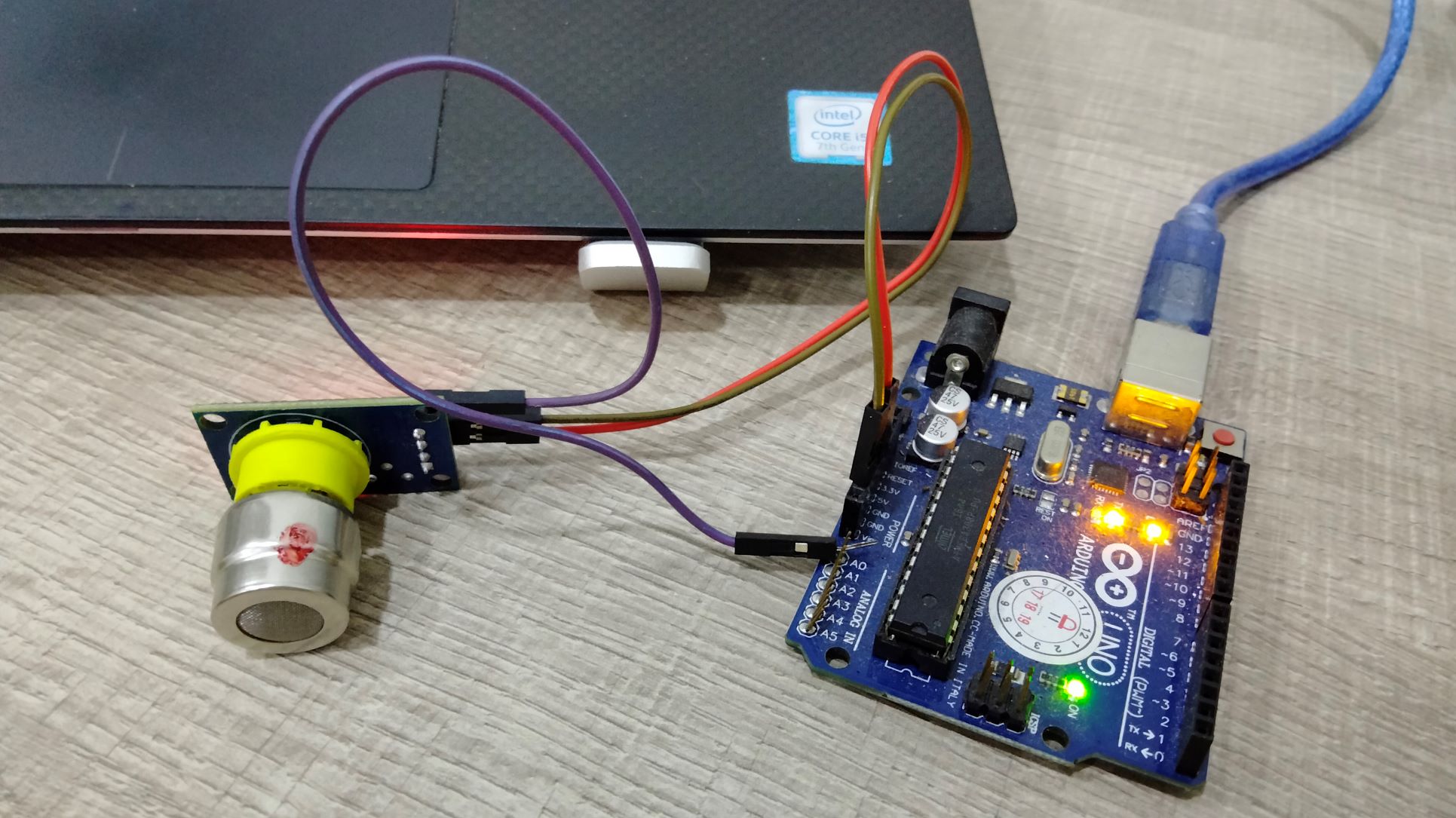
I attempted to make a Processing interface to visualize the reading of a CO2 sensor for my final project, with the help of this tutorial.
Firstly, I connected the 3 wires from the sensor to Arduino Uno’s VCC, GND and A0 respectively.
Arduino code
Next, I uploaded the following sketch to Arduino.
void setup() {
  // initialize the serial communication:
  Serial.begin(9600);
}

void loop() {
  // send the value of analog input 0:
  Serial.println(analogRead(A0));
  // wait a bit for the analog-to-digital converter to stabilize after the last
  // reading:
  delay(2);
}
Processing code
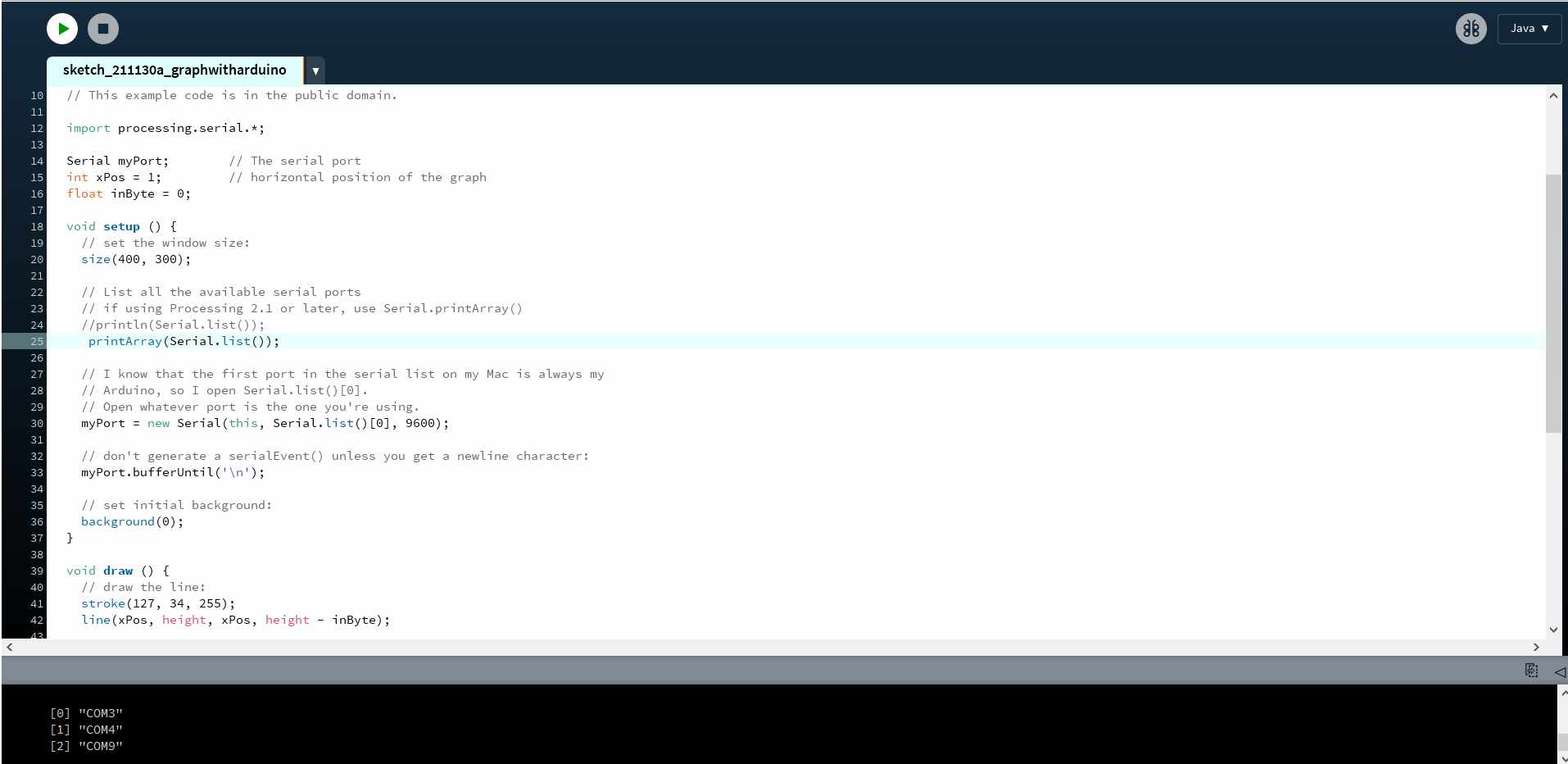
Executing the sketch lets me see a list of serial ports available. The one I should connect to is 2.
  // Graphing sketch

  // This program takes ASCII-encoded strings from the serial port at 9600 baud
  // and graphs them. It expects values in the range 0 to 1023, followed by a
  // newline, or newline and carriage return

  // created 20 Apr 2005
  // updated 24 Nov 2015
  // by Tom Igoe
  // This example code is in the public domain.

  import processing.serial.*;

  Serial myPort;        // The serial port
  int xPos = 1;         // horizontal position of the graph
  float inByte = 0;

  void setup () {
    // set the window size:
    size(400, 300);

    // List all the available serial ports
    // if using Processing 2.1 or later, use Serial.printArray()
    println(Serial.list());

    // I know that the first port in the serial list on my Mac is always my
    // Arduino, so I open Serial.list()[0].
    // Open whatever port is the one you're using.
    myPort = new Serial(this, Serial.list()[0], 9600);

    // don't generate a serialEvent() unless you get a newline character:
    myPort.bufferUntil('\n');

    // set initial background:
    background(0);
  }

  void draw () {
    // draw the line:
    stroke(127, 34, 255);
    line(xPos, height, xPos, height - inByte);

    // at the edge of the screen, go back to the beginning:
    if (xPos >= width) {
      xPos = 0;
      background(0);
    } else {
      // increment the horizontal position:
      xPos++;
    }
  }

  void serialEvent (Serial myPort) {
    // get the ASCII string:
    String inString = myPort.readStringUntil('\n');

    if (inString != null) {
      // trim off any whitespace:
      inString = trim(inString);
      // convert to an int and map to the screen height:
      inByte = float(inString);
      println(inByte);
      inByte = map(inByte, 0, 1023, 0, height);
    }
  }
With the port numbers seen printed on the console, I updated the serial port number in following line accordingly to 2.
myPort = new Serial(this, Serial.list()[2], 9600);
Now when the program was running, you can see a thin line in violet colour being generated. I tried to blow into the sensor to see if the line would fluctuate. Surprisingly nothing happened. That’s when I realized that the signal is probably too small for the eyes to discern.
To amplify the displayed height, I modified the following line from
line(xPos, height, xPos, height - inByte); to line(xPos, height, xPos, height - inByte*500);
This change increased the line’s thickness, as shown below.
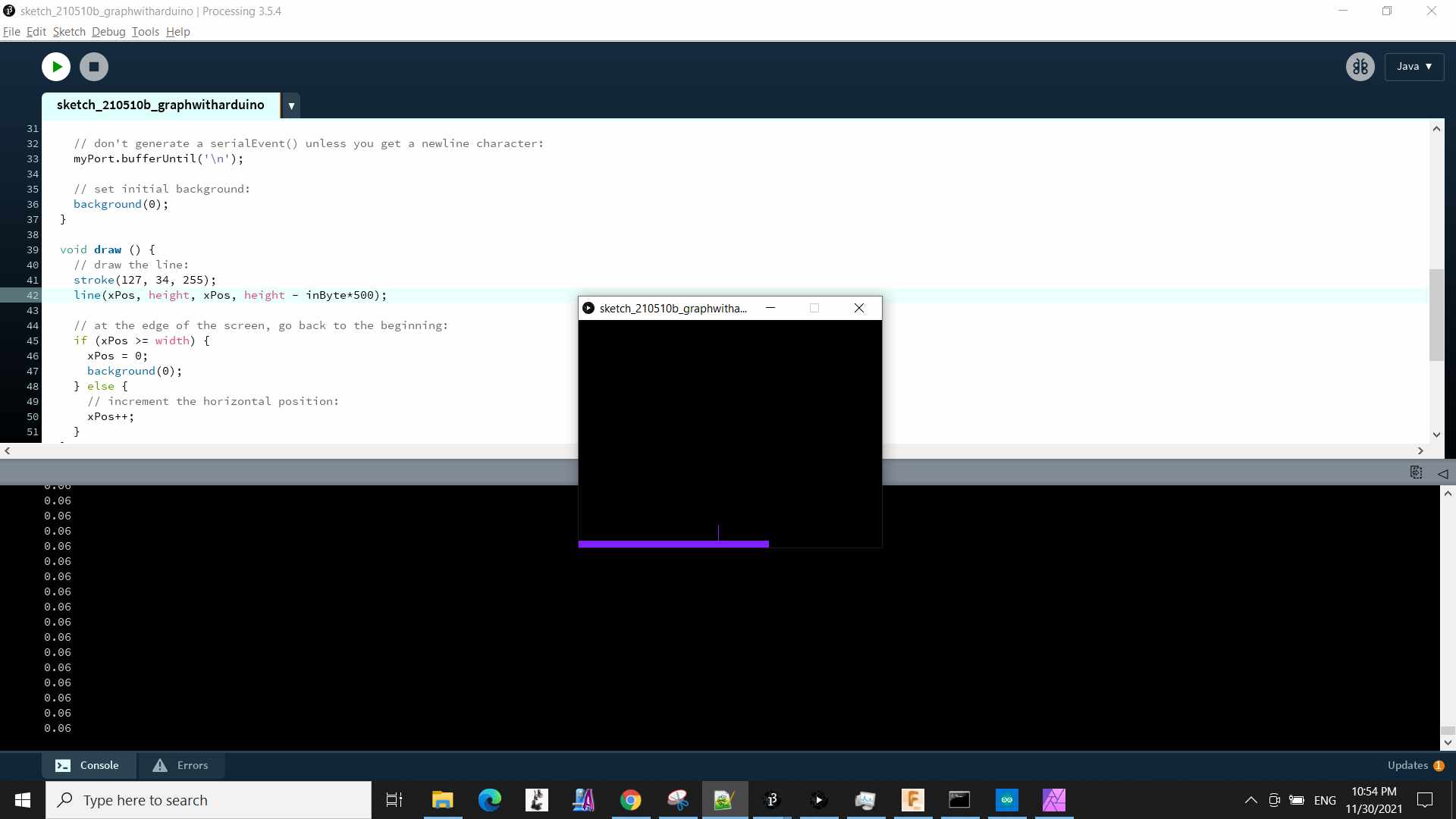
Again, I tried blowing into the sensor. This time the changes became visible.
Overall, this is a very basic interface that can be quickly set up.
Python interface
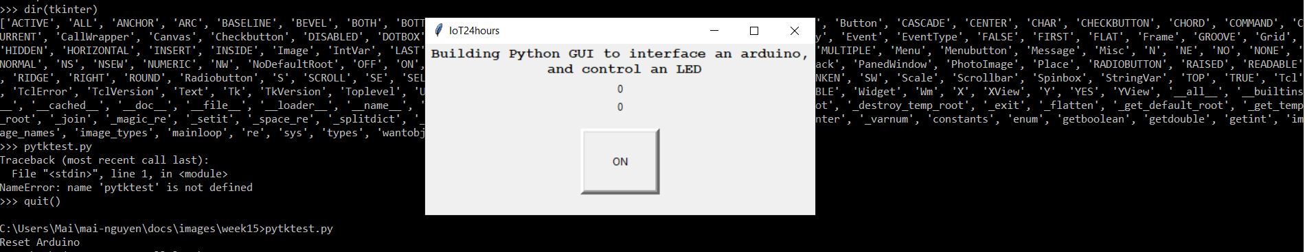
Previously I had run python commands from a Windows terminal but making a Python GUI interface was something new to me. For this maiden attempt, I referred to “Python GUI (Tkinter) with Arduino” tutorial by Stackpython. It explained how to build a GUI app that toggles an Arduino’s on-board LED.
The app makes use of ‘tkinter’, the most popular Python package for GUI-making. There are 2 steps to this, programming Arduino and running a Python script, both of which are provided below.
Arduino code
// Arduino IDE:
// File -> Examples -> 04.Communication -> PhysicalPixel

const int ledPin = 13; // pin the LED is attached to
int incomingByte;      // variable stores  serial data

void setup() {
  // initialize serial communication:
  Serial.begin(9600);
  // initialize the LED pin as an output:
  pinMode(ledPin, OUTPUT);
}

void loop() {
  // see if there's incoming serial data:
  if (Serial.available() > 0) {
    // read the oldest byte in the serial buffer:
    incomingByte = Serial.read();
    // if it's a capital H (ASCII 72), turn on the LED:
    if (incomingByte == 'H') {
      digitalWrite(ledPin, HIGH);
      Serial.println("Getting H"); //print out to serial monitor to check state
    }
    // if it's an L (ASCII 76) turn off the LED:
    if (incomingByte == 'L') {
      digitalWrite(ledPin, LOW);
      Serial.println("Getting L"); //print out to serial monitor to check state
    }
  }
}
Python code
import serial
import time
import tkinter


def quit():
    global tkTop
    ser.write(bytes('L', 'UTF-8'))
    tkTop.destroy()

def set_button1_state():
        global b
        b += 1
        varLabel.set("LED ON ")
        ser.write(bytes('H', 'UTF-8'))
        varLabel2.set(b)
        print(b)

def set_button2_state():
        varLabel.set("LED OFF")
        ser.write(bytes('L', 'UTF-8'))

ser = serial.Serial('com7', 9600)
print("Reset Arduino")
time.sleep(3)
ser.write(bytes('L', 'UTF-8'))

tkTop = tkinter.Tk()
tkTop.geometry('300x200')
tkTop.title("IoT24hours")
label3 = tkinter.Label(text = 'Building Python GUI to interface an arduino,'
                      '\n and control an LED',font=("Courier", 12,'bold')).pack()
tkTop.counter = 0
b = tkTop.counter

varLabel = tkinter.IntVar()
tkLabel = tkinter.Label(textvariable=varLabel, )
tkLabel.pack()

varLabel2 = tkinter.IntVar()
tkLabel2 = tkinter.Label(textvariable=varLabel2, )
tkLabel2.pack()

button1 = tkinter.IntVar()
button1state = tkinter.Button(tkTop,
    text="ON",
    command=set_button1_state,
    height = 4,
    fg = "black",
    width = 8,
    bd = 5,
    activebackground='green'
)
button1state.pack(side='top', ipadx=10, padx=10, pady=15)

button2 = tkinter.IntVar()
button2state = tkinter.Button(tkTop,
    text="OFF",
    command=set_button2_state,
    height = 4,
    fg = "black",
    width = 8,
    bd = 5
)
button2state.pack(side='top', ipadx=10, padx=10, pady=15)

tkButtonQuit = tkinter.Button(
    tkTop,
    text="Quit",
    command=quit,
    height = 4,
    fg = "black",
    width = 8,
    bg = 'yellow',
    bd = 5
)
tkButtonQuit.pack(side='top', ipadx=10, padx=10, pady=15)

tkinter.mainloop()
error “ModuleNotFoundError: No module named ‘serial’” pip install pyserial –user pip install tkinter –user
This command prompted the following error message to appear: “ERROR: Could not find a version that satisfies the requirement tkinter (from versions: none) ERROR: No matching distribution found for tkinter”
NameError: name ‘tkinter’ is not defined
pip install tk
module ‘tk’ has no attribute ‘Tk’
dir(tkinter) [‘ACTIVE’, ‘ALL’, ‘ANCHOR’, ‘ARC’, ‘BASELINE’, ‘BEVEL’, ‘BOTH’, ‘BOTTOM’, ‘BROWSE’, ‘BUTT’, ‘BaseWidget’, ‘BitmapImage’, ‘BooleanVar’, ‘Button’, ‘CASCADE’, ‘CENTER’, ‘CHAR’, ‘CHECKBUTTON’, ‘CHORD’, ‘COMMAND’, ‘CURRENT’, ‘CallWrapper’, ‘Canvas’, ‘Checkbutton’, ‘DISABLED’, ‘DOTBOX’, ‘DoubleVar’, ‘E’, ‘END’, ‘EW’, ‘EXCEPTION’, ‘EXTENDED’, ‘Entry’, ‘Event’, ‘EventType’, ‘FALSE’, ‘FIRST’, ‘FLAT’, ‘Frame’, ‘GROOVE’, ‘Grid’, ‘HIDDEN’, ‘HORIZONTAL’, ‘INSERT’, ‘INSIDE’, ‘Image’, ‘IntVar’, ‘LAST’, ‘LEFT’, ‘Label’, ‘LabelFrame’, ‘Listbox’, ‘MITER’, ‘MOVETO’, ‘MULTIPLE’, ‘Menu’, ‘Menubutton’, ‘Message’, ‘Misc’, ‘N’, ‘NE’, ‘NO’, ‘NONE’, ‘NORMAL’, ‘NS’, ‘NSEW’, ‘NUMERIC’, ‘NW’, ‘NoDefaultRoot’, ‘OFF’, ‘ON’, ‘OUTSIDE’, ‘OptionMenu’, ‘PAGES’, ‘PIESLICE’, ‘PROJECTING’, ‘Pack’, ‘PanedWindow’, ‘PhotoImage’, ‘Place’, ‘RADIOBUTTON’, ‘RAISED’, ‘READABLE’, ‘RIDGE’, ‘RIGHT’, ‘ROUND’, ‘Radiobutton’, ‘S’, ‘SCROLL’, ‘SE’, ‘SEL’, ‘SEL_FIRST’, ‘SEL_LAST’, ‘SEPARATOR’, ‘SINGLE’, ‘SOLID’, ‘SUNKEN’, ‘SW’, ‘Scale’, ‘Scrollbar’, ‘Spinbox’, ‘StringVar’, ‘TOP’, ‘TRUE’, ‘Tcl’, ‘TclError’, ‘TclVersion’, ‘Text’, ‘Tk’, ‘TkVersion’, ‘Toplevel’, ‘UNDERLINE’, ‘UNITS’, ‘VERTICAL’, ‘Variable’, ‘W’, ‘WORD’, ‘WRITABLE’, ‘Widget’, ‘Wm’, ‘X’, ‘XView’, ‘Y’, ‘YES’, ‘YView’, ‘all’, ‘builtins’, ‘cached’, ‘doc’, ‘file’, ‘loader’, ‘name’, ‘package’, ‘path’, ‘spec’, ‘_cnfmerge’, ‘_default_root’, ‘_destroy_temp_root’, ‘_exit’, ‘_flatten’, ‘_get_default_root’, ‘_get_temp_root’, ‘_join’, ‘_magic_re’, ‘_setit’, ‘_space_re’, ‘_splitdict’, ‘_stringify’, ‘_support_default_root’, ‘_test’, ‘_tkerror’, ‘_tkinter’, ‘_varnum’, ‘constants’, ‘enum’, ‘getboolean’, ‘getdouble’, ‘getint’, ‘image_names’, ‘image_types’, ‘mainloop’, ‘re’, ‘sys’, ‘types’, ‘wantobjects’]
C:\Users\Mai\mai-nguyen\docs\images\week15>pytktest.py
Reset Arduino
Traceback (most recent call last):
File “C:\Users\Mai\mai-nguyen\docs\images\week15\pytktest.py”, line 27, in
Individual Assignment
For this assignment, I want to change the colours of Neopixel by clicking on a hue in Processing. The Neopixels are controlled by ESP-32 CAM board.
Let’s first check the pinout of ESP32-CAM.
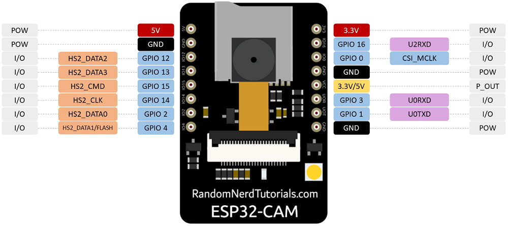 Source: https://randomnerdtutorials.com
Exploring Processing and Arduino Handshaking
I followed this handy tutorial by Sparkfun
Code for ESP32-CAM
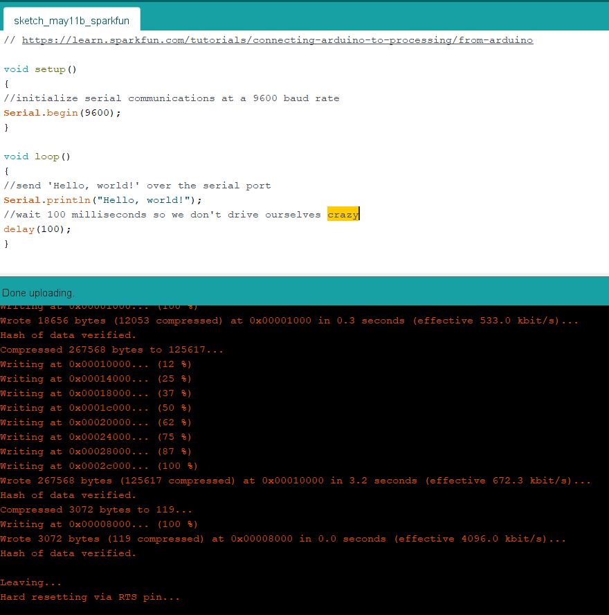
I flashed the following code to ESP32-CAM.
// Source: https://learn.sparkfun.com/tutorials/connecting-arduino-to-processing/from-arduino

void setup()
{
//initialize serial communications at a 9600 baud rate
Serial.begin(9600);
}

void loop()
{
//send 'Hello, world!' over the serial port
Serial.println("Hello, world!");
//wait 100 milliseconds so we don't drive ourselves crazy
delay(100);
}
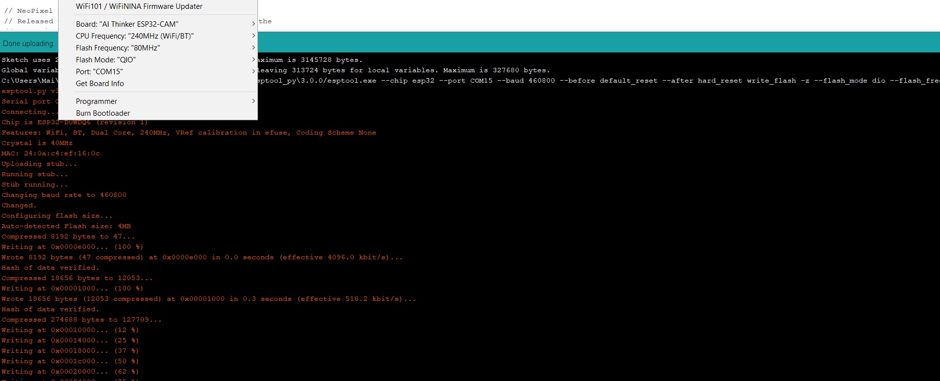
Having selected AI Thinker ESP32-CAM Board (under Tools) and an appropriate Port for the USB connector that came with the ESP32-CAM, I hit the ‘upload’ button and successfully loaded the code onto the ESP32-CAM.
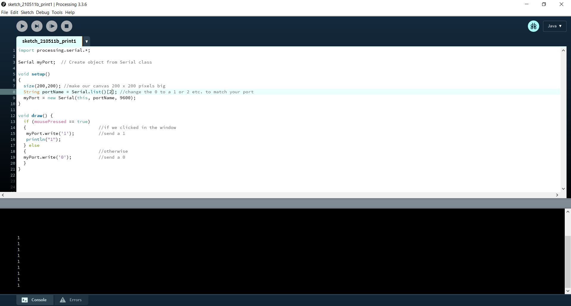
Code for Processing
import processing.serial.*; //import the Serial library
 Serial myPort;  //the Serial port object
 String val;
// since we're doing serial handshaking,
// we need to check if we've heard from the microcontroller
boolean firstContact = false;


void setup() {
  size(200, 200); //make our canvas 200 x 200 pixels big
  //  initialize your serial port and set the baud rate to 9600
  myPort = new Serial(this, Serial.list()[0], 9600);
  myPort.bufferUntil('\n');
}

void draw() {
//  if (mousePressed == true)
//  {                           //if we clicked in the window
//   myPort.write('1');         //send a 1
//   println("1");
//  } else
//  {                           //otherwise
// myPort.write('0');          //send a 0
//  }
}

void serialEvent( Serial myPort) {
//put the incoming data into a String -
//the '\n' is our end delimiter indicating the end of a complete packet
val = myPort.readStringUntil('\n');
//make sure our data isn't empty before continuing
if (val != null) {
  //trim whitespace and formatting characters (like carriage return)
  val = trim(val);
  println(val);

  //look for our 'A' string to start the handshake
  //if it's there, clear the buffer, and send a request for data
  if (firstContact == false) {
    if (val.equals("A")) {
      myPort.clear();
      firstContact = true;
      myPort.write("A");
      println("contact");
    }
  }
  else { //if we've already established contact, keep getting and parsing data
    println(val);

    if (mousePressed == true)
    {                           //if we clicked in the window
      myPort.write('1');        //send a 1
      println("1");
    }

    // when you've parsed the data you have, ask for more:
    myPort.write("A");
    }
  }
}
The above code ran smoothly.
Programming the ESP32-CAM and Neopixels
Connecting Neopixels to ESP32-CAM to FTDI programmer
I unplugged the ESP32-CAM from the Serial interface shield that originaly came with it and connected to an FTDI programmer. The board is powered through the 5V pin, as shown in below diagram.
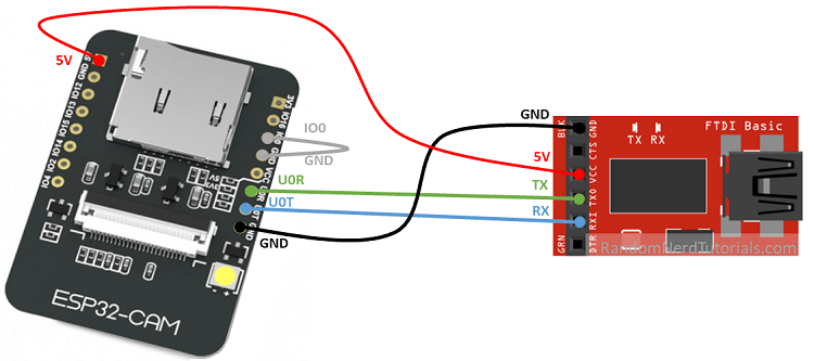 Source: https://randomnerdtutorials.com
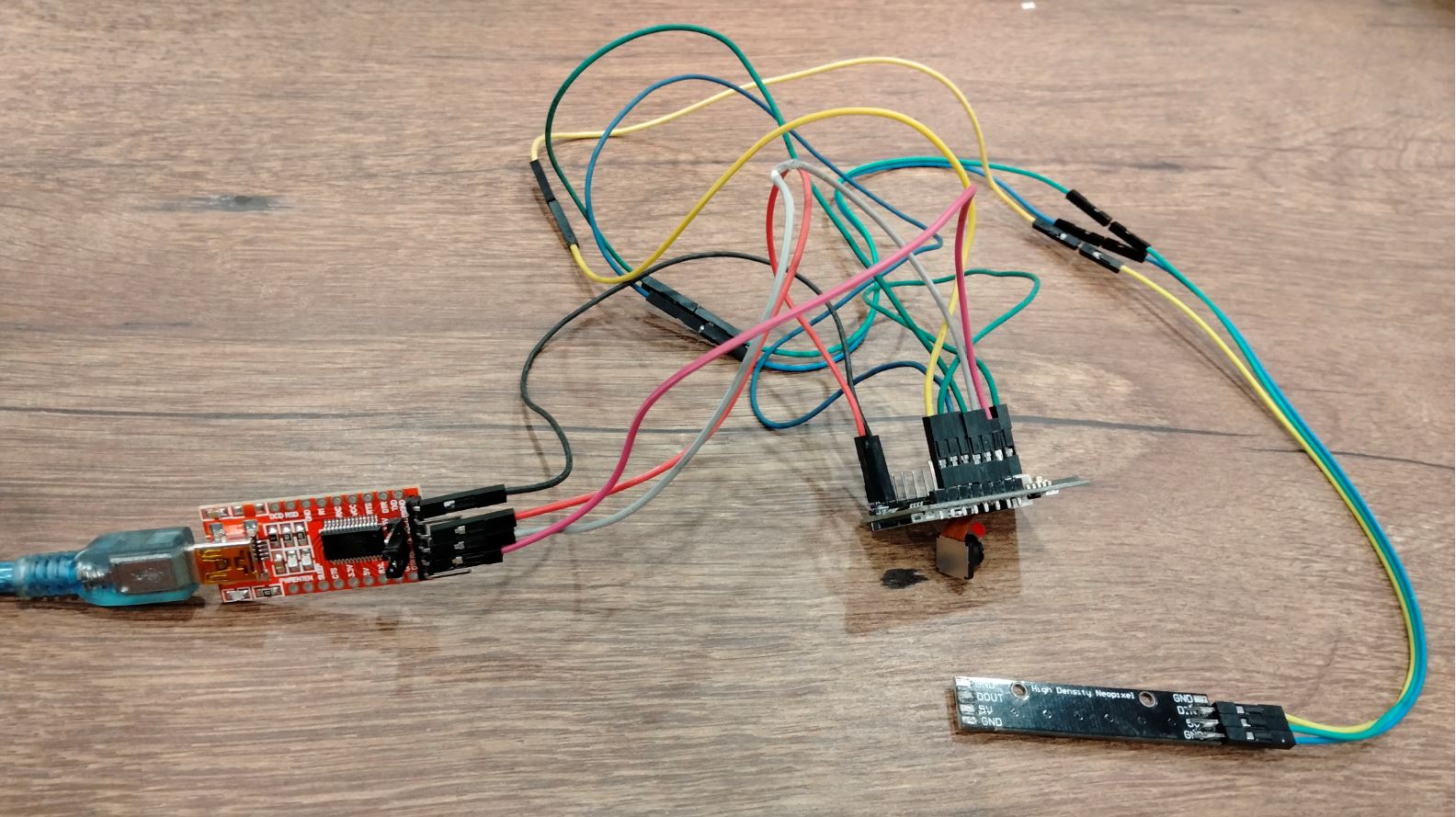
Here is a picture of my complete circuit, with the Neopixels connected as well.
Code for Neopixels
int i = 0;
char buf[20];
int color[5];

// This code changes the colour of an LED strip according to a hue selected by user in Processing interface.
// Adapted by Mai Nguyen for Fabacademy 2021 based on Yuki Oka's project.

#include <FastLED.h>

#define LED_PIN     16
#define NUM_LEDS    8
#define BRIGHTNESS 200

CRGB leds[NUM_LEDS];

#define DELAYVAL 500 // Time (in milliseconds) to pause between pixels

void setup(){
  Serial.begin(115200);
  FastLED.addLeds<WS2812, LED_PIN, GRB>(leds, NUM_LEDS);
  FastLED.setBrightness(BRIGHTNESS);
}

void loop(){
  if (Serial.available()){
    //pixels.clear(); // Set all pixel colors to 'off'
    buf[i] = Serial.read();
    if (buf[i] == 'e'){ // set 'e' at the end of the last caracter
      buf[i] = '\0';
      //Serial.println(buf);

      color[0] = atoi(strtok(buf, ","));
      color[1] = atoi(strtok(NULL, ",")); // use NULL from second group
      color[2] = atoi(strtok(NULL, ","));

      for (i=0; i<NUM_LEDS; i++){
        leds[i] = CRGB(color[0], color[1], color[2]);
        FastLED.show();  // Send the updated pixel colors to the hardware.
        //send back data to processing
      Serial.println("color[0],color[1],color[2]");
      }

    i = 0;
    }
    else {
      i++;
    }
  }
}
When I first flashed the code below to ESP32-CAM, the following error came up
“Error: A fatal error occurred: Failed to connect to ESP32: Timed out waiting for packet header”

I checked the wiring and realized that I had totally forgot to connect RX and TX between the FTDI programmer and ESP32-CAM. Once this was rectified, the error was still there.
Referring to this ESP-32 CAM troubleshooting guide, I checked everything mentioned but still I had difficulty solving the issue.
Having seen someone on the Arduino forum mention that he had troubles uploading at any baud rate higher than 115200, I reduced the ESP32 Cam’s Upload speed from 460800 to 115200 by modifying a configuration file for ESP32 named Board.txt.
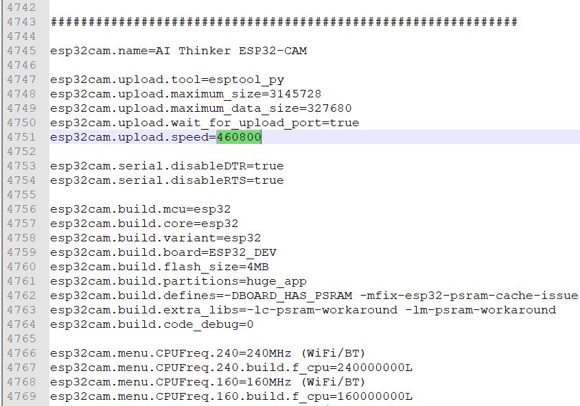
The Board.txt file was found in the following location. Remember to restart the Arduino IDE for the change to take effects.
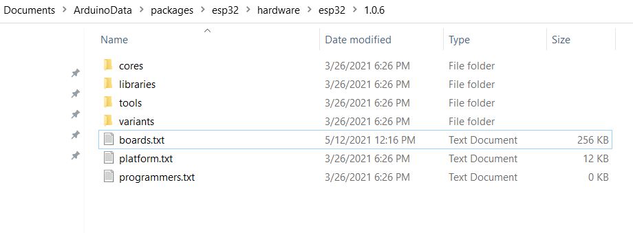
Unfortunately uploading at 115200 baud rate also failed.

Eventually I changed to a different ESP32-CAM board. Before flashing, I pressed Reset. It says “waiting for download”.
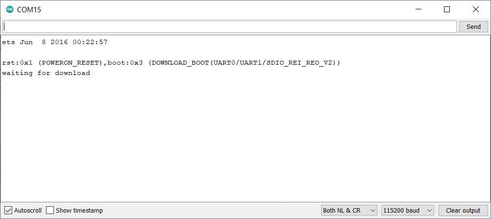
I pressed Upload and magically it worked this time, even at 460800 baud rate. My conclusion is that the previous ESP32-CAM board failed.
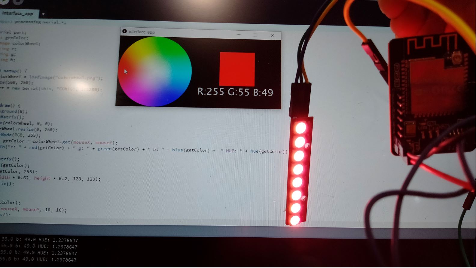
However, the LEDs still did not light up. I used a multimeter to check continuity of the signal output from the ESP-32. Not just one, but two wires in series were broken. Once I replaced them, the LEDs lit up when I clicked on a hue in the colourwheel.
Code for Processing
I modified a programme created by Yuki Oka, a previous Fabacademy student, in order to keep up with the latest changes in Processing syntax. My code is also attached as a .zip file below.
import processing.serial.*;

Serial port;
int getColor;
PImage colorWheel;
String r;
String g;
String b;

void setup() {
  colorWheel = loadImage("colorwheel.png");
  size(560, 250);
  port = new Serial(this, "COM15", 115200);
}

void draw() {
  background(0);
  pushMatrix();
  image(colorWheel, 0, 0);
  colorWheel.resize(0, 250);
  colorMode(RGB, 255);
  color getColor = colorWheel.get(mouseX, mouseY);
  println("r: " + red(getColor) + " g: " + green(getColor) + " b: " + blue(getColor) +  " HUE: " + hue(getColor));

  pushMatrix();
  stroke(getColor);
  fill(getColor, 255);
  rect(width * 0.62, height * 0.2, 120, 120);
  popMatrix();


  fill(getColor);
  ellipse(mouseX, mouseY, 10, 10);
  popMatrix();

  pushMatrix();
  fill(217);
  noStroke();
  textSize(33);
  textAlign(CENTER, CENTER);
  text("R:" + int(red(getColor)) + " G:" + int(green(getColor)) + " B:" + int(blue(getColor)), width * 0.72, height * 0.75);
  popMatrix();
  //println(str(int(red(getColor))) + "," + str(int(green(getColor))) + "," + str(int(blue(getColor)))+ "e");
  r = str(int(red(getColor)));
  g = str(int(green(getColor)));
  b = str(int(blue(getColor)));


  if (mousePressed) {
  port.write(r + "," + g + "," + b + "e");
  println("sent to arduino!");
  }
}
Video showcase
Key learning points
In summary, this week my biggest take-aways are
- How to create a visual application / interface in Processing and Python
- How to interface Processing and Arduino IDE
- ESP-32 CAM programming using Arduino IDE
What I did not expect was spending a lot of time troubleshooting ESP-32 serial connection issues and realizing that my board failed. Other than that, I had fun playing with Processing and Neopixels. I hope to take it further with Processing to develop interactive applications after completing Fabacademy.
Useful links
- Sparkfun’s guide on connecting Arduino to Processing
- Tutorial on using a Processing graph to visualize sensor values
- Tutorial on controlling Arduino’s LED with Python GUI
- Displaying values from Arduino using Processing
- Yuki Oka’s Fabacademy assignment
- Tatsuro Homma’s Fabacademy assignment
Files
- Code for Processing interface
- Code for Arduino working with Processing interface
- Code for Python GUI
- [Code for Arduino working with Python GUI]
- Code for ESP32-CAM
- Code for Processing