8. Computer-controlled machining
This week I get to one of my favourite things in the maker world, CNC-ing.
Group assignment
- do your lab’s safety training
- test runout, alignment, speeds, feeds, materials, and toolpaths for your machine
Individual assignment
- make (design+mill+assemble) something big (~meter-scale)
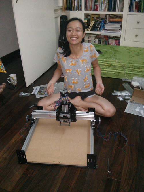
Hero shot

A long CNC Affair
This week’s assignment brings back the memories of building my first CNC machine 6 years ago. I bought a do-it-yourself kit from Inventables for around $400 with the intention of making do-it-yourself woodblock printing kít for a cultural preservation project. It was a lot of fun to assemble and test it with my boyfriend.
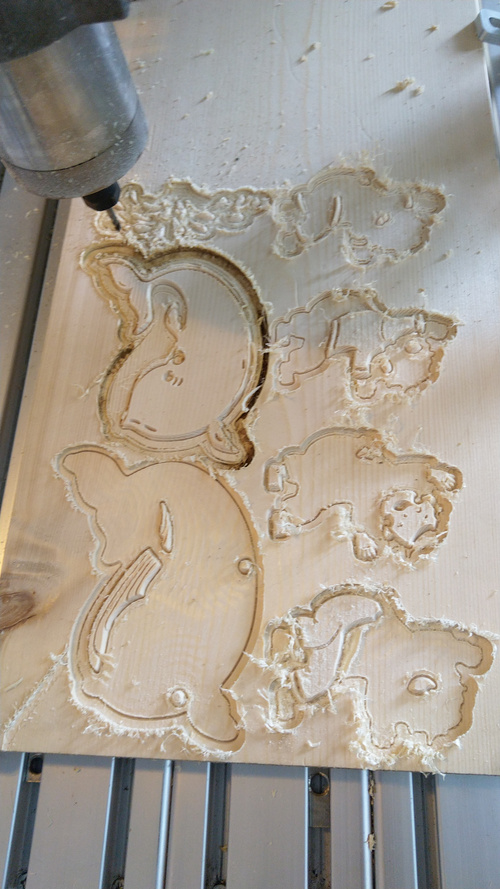
When I started selling more kits, I outsourced the production to machining shops.
The last things I milled before FabAcademy were also woodblocks.
I’ve always wanted a full-scale CNC machine for making furnitures but our lab could not afford the space and funding.
Individual assignment
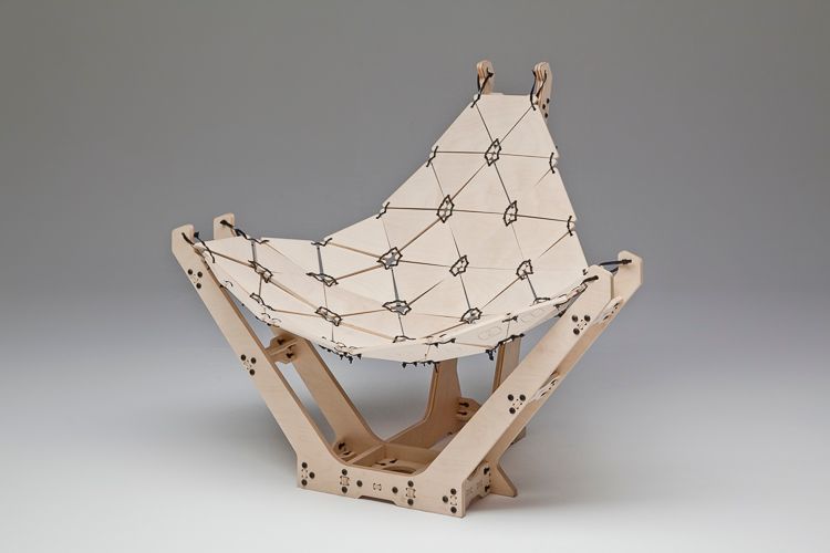
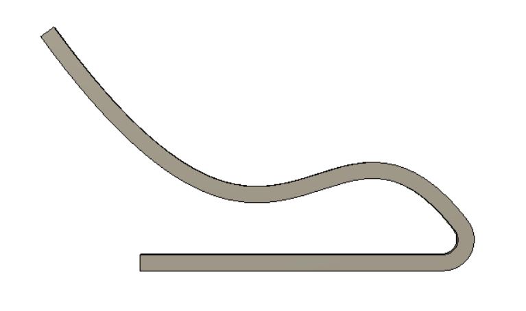
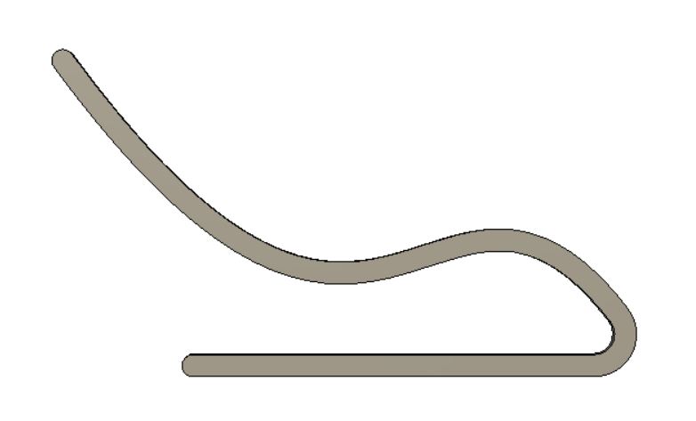
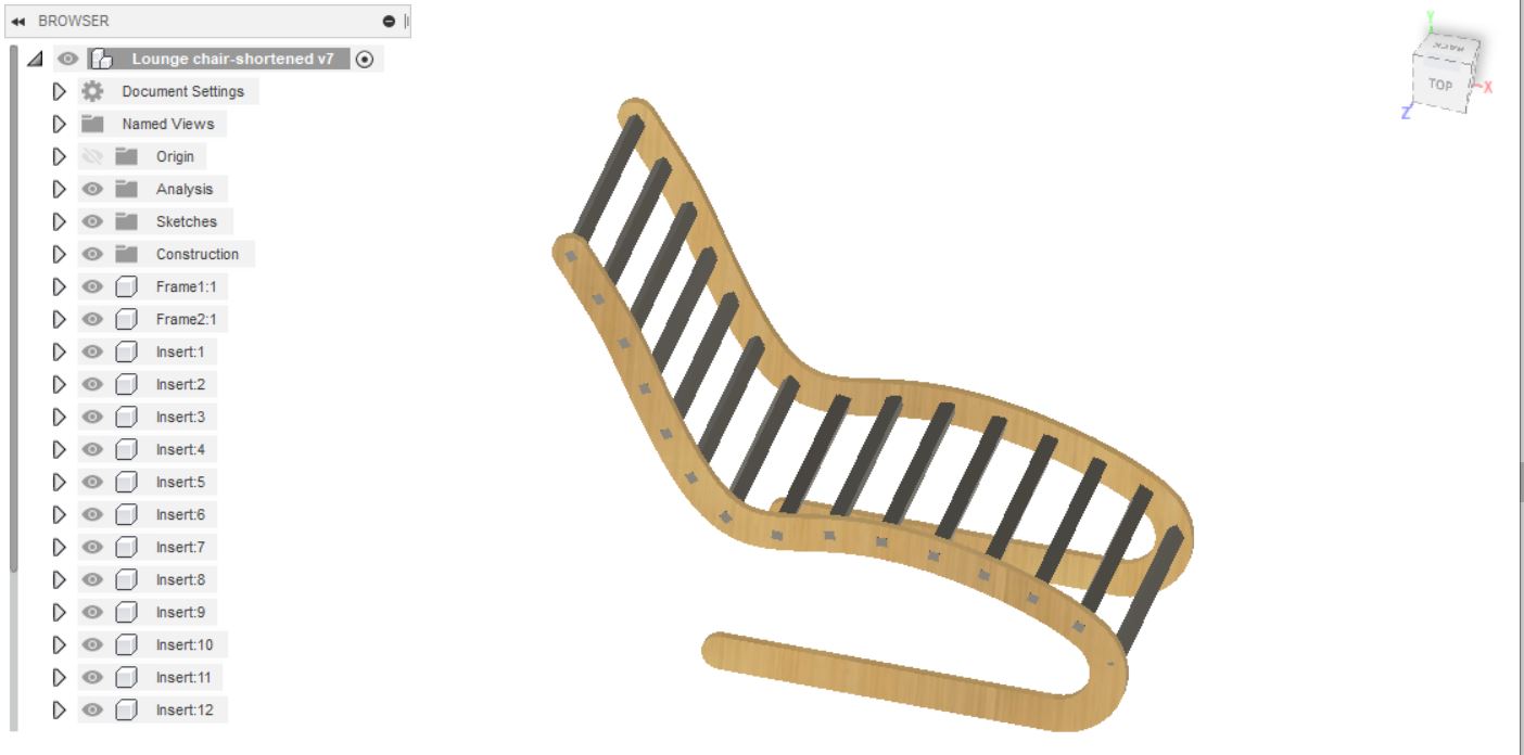
I had a hard time picking one idea to CNC. A rocking chair, a hammock stand, beach chair, just to name a few … and this ChaiseLounge:
This is a beautiful and fairly complex design named by Italian designer Pietro Leoni. It is open-sourced and you can download the building files from the website.
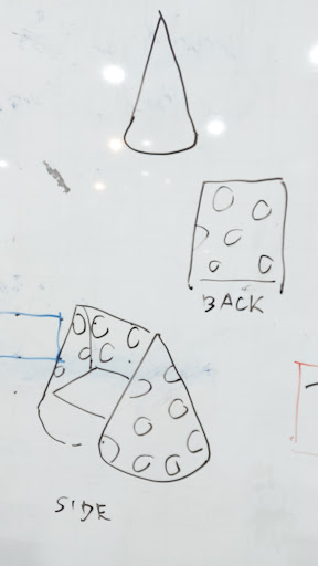
There are just too many cool things you can make with a CNC machine. At some point, I want to make a rocking chair in the shape of a cheese block.
In the end, I settled on a relaxing chair because an IKEA’s Poang chair has been on my wish-list for a couple of years now.
For this assignment, I will be using a maker friend’s CNC machine since the one in our lab, having a work area of 40x60cm is not ideal for making something big.
Dogbone Add-in for Fusion360
To make things easier, I googled dogbone fusion 360 tool and this video tutorial by Patrick Rainsbury came up. He developed a add-in to make dogbone design in Fusion360 easier. I downloaded the add-in from the Github link below the video, and followed the installation guide on this page.
I typed %AppData%\Autodesk\Autodesk Fusion 360\API\AddIns in a Window Explorer browser, and copied the unzipped folder there.
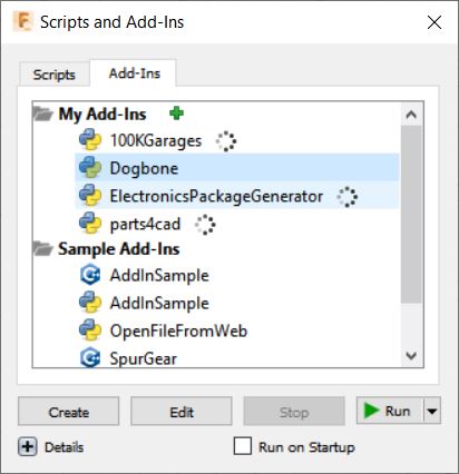
In Fusion360, I clicked on Add-ins pane.
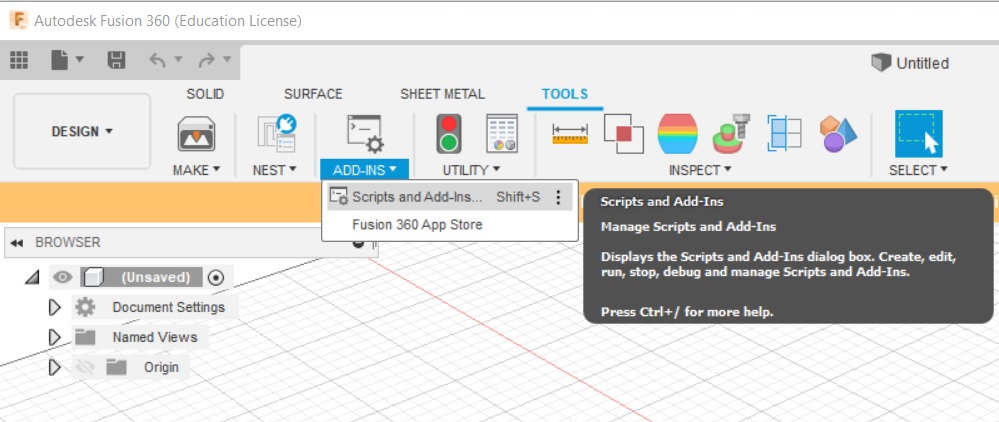
When Scripts and Add-Ins dialog opened, I clicked Add-Ins tab, selected Dogbone under My Add-ins. Also ticked Run on start-up and clicked Run.
Design in Fusion360
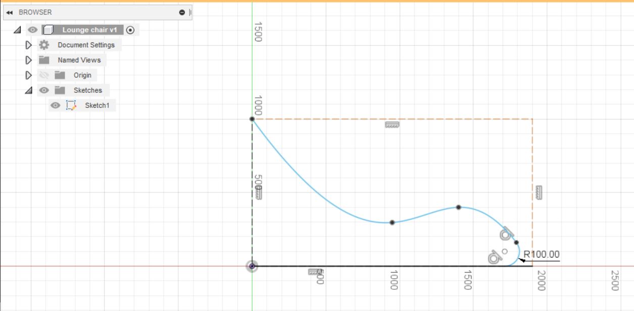
Design the main frame
We begin by drawing construction lines.

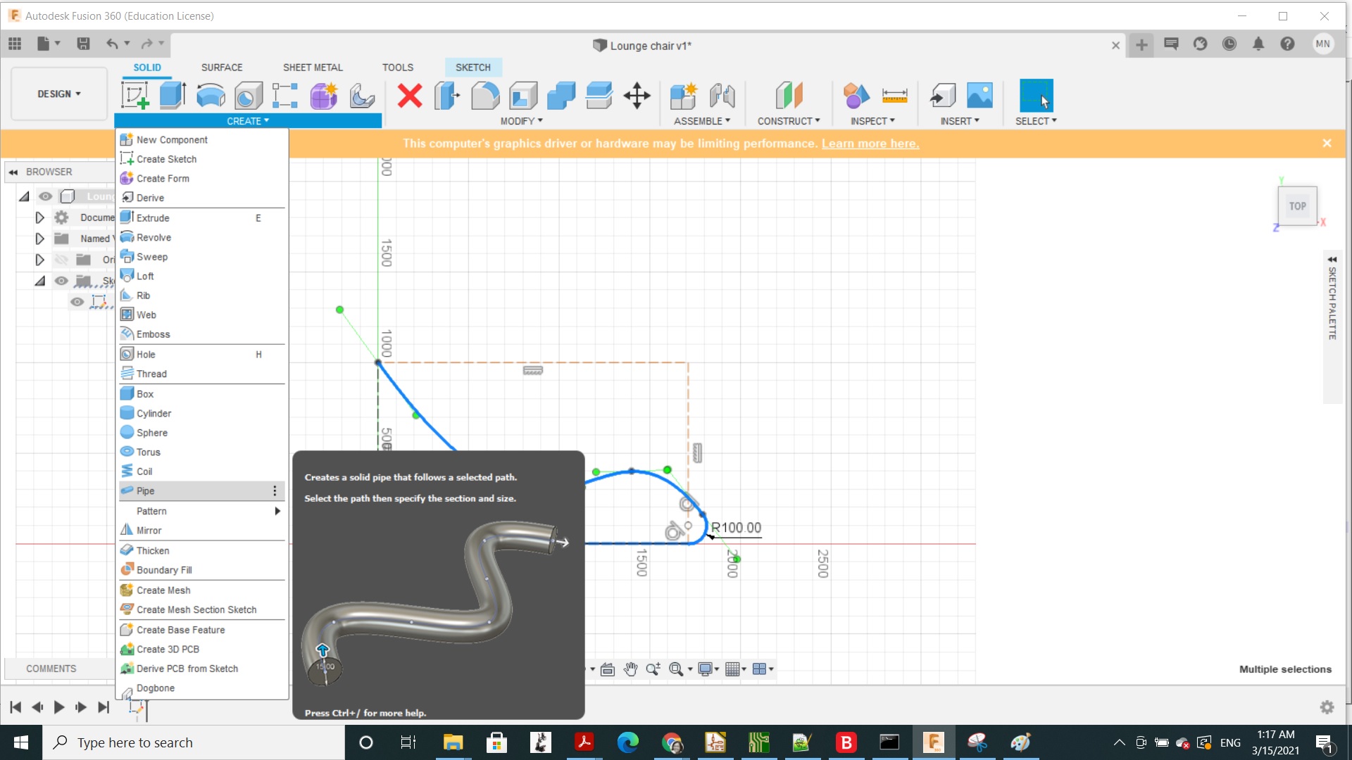
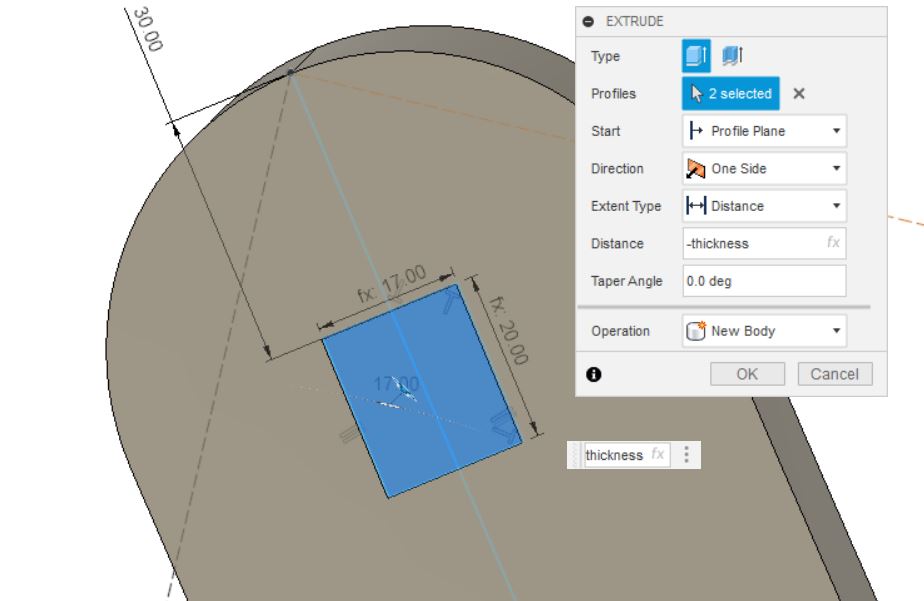
Click on the outer surface. Select Extrude function
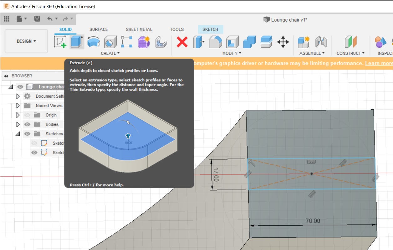
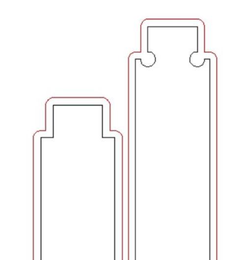
We will extrude inwards 33mm to thin the wood to the thickness of the actual material, 17mm in this case.
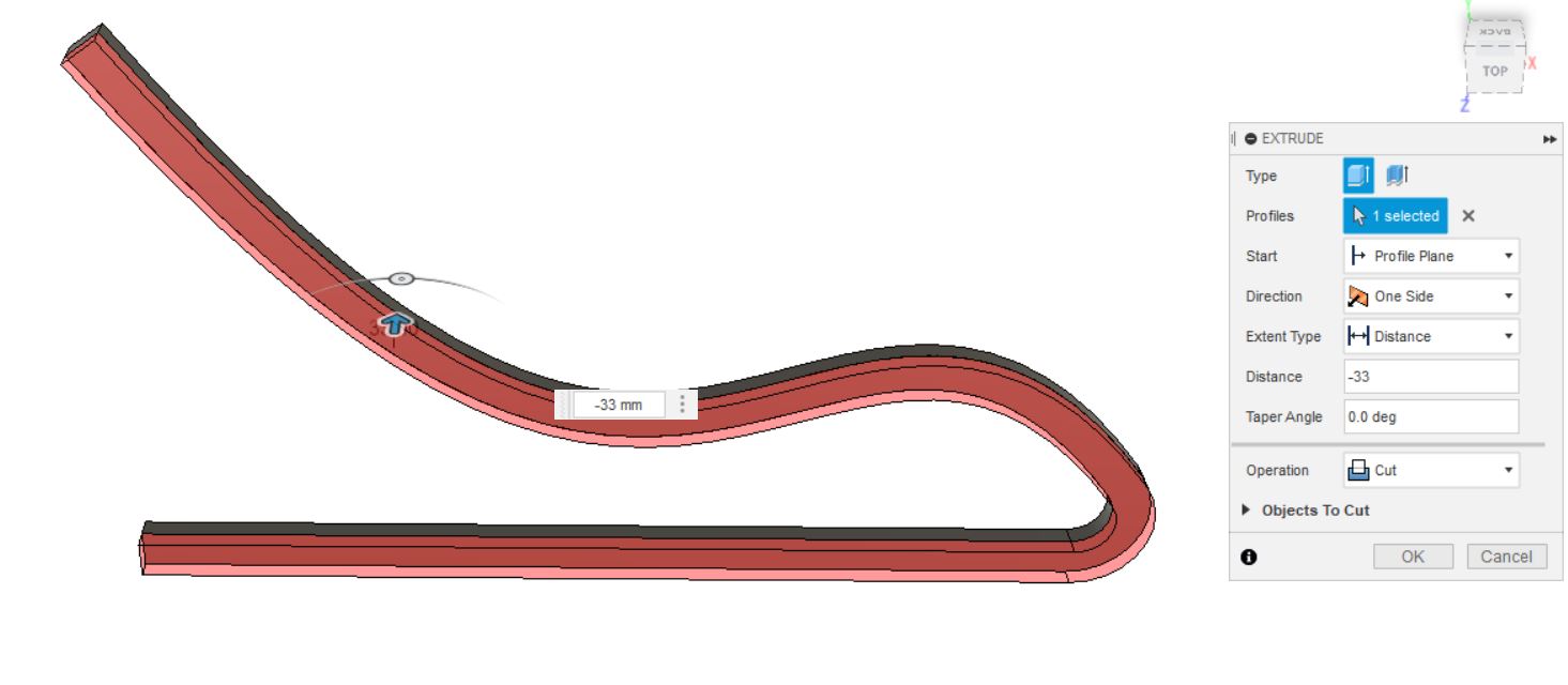
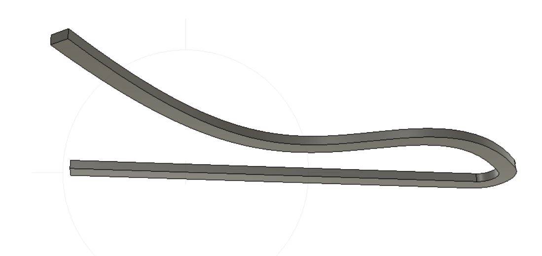
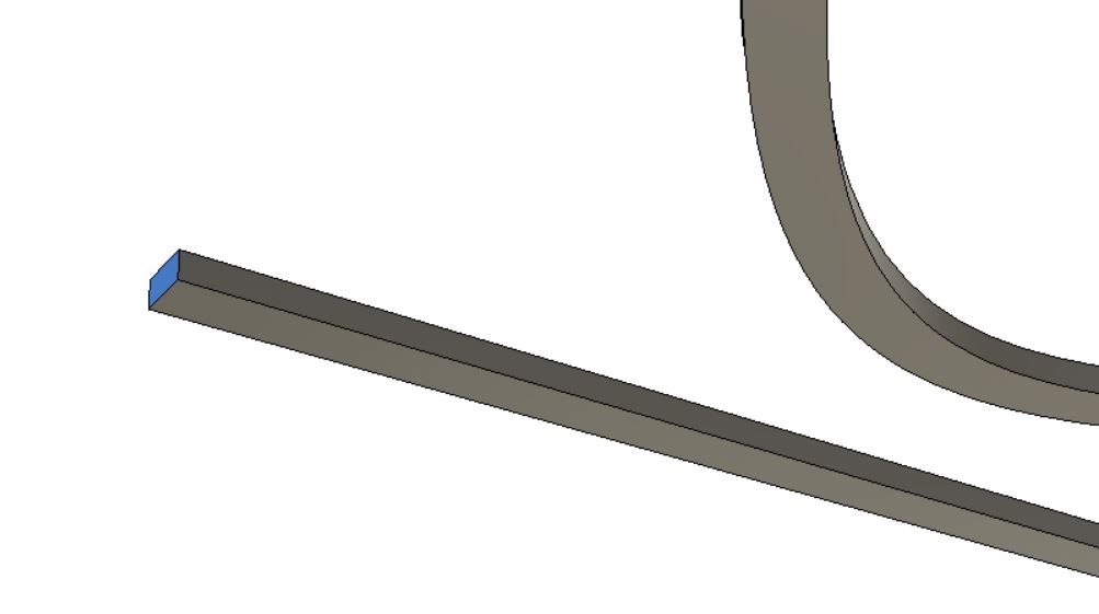
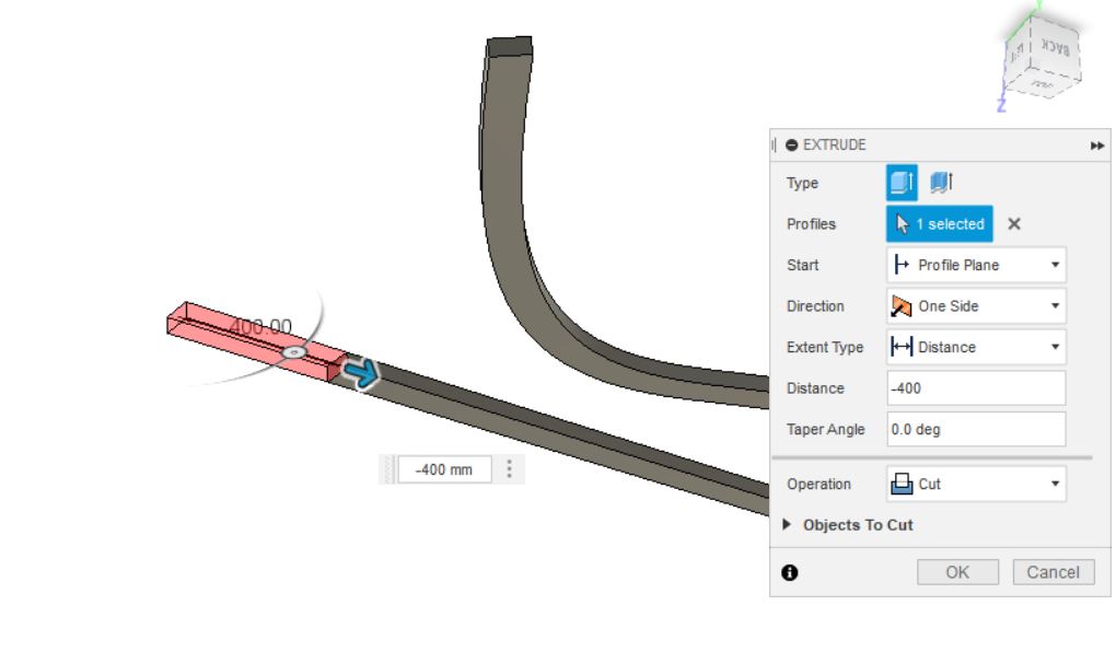
Next, let us shorten the ground support, again also by extruding.
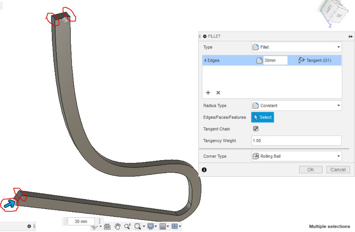
We are going to round off the square end to make it look sleeker. In Modify pane, click Select Fillet. Click on the 4 edges to be rounded and specify a radius of 30mm.
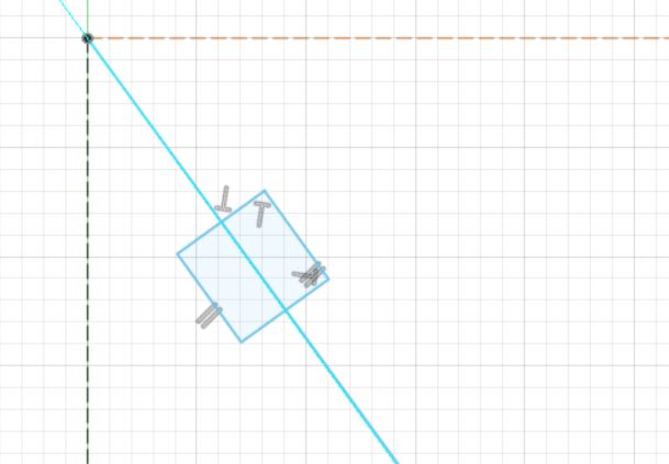
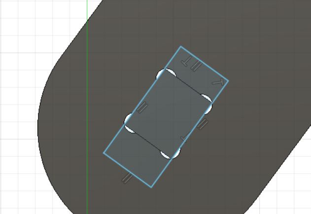
Add insert holes
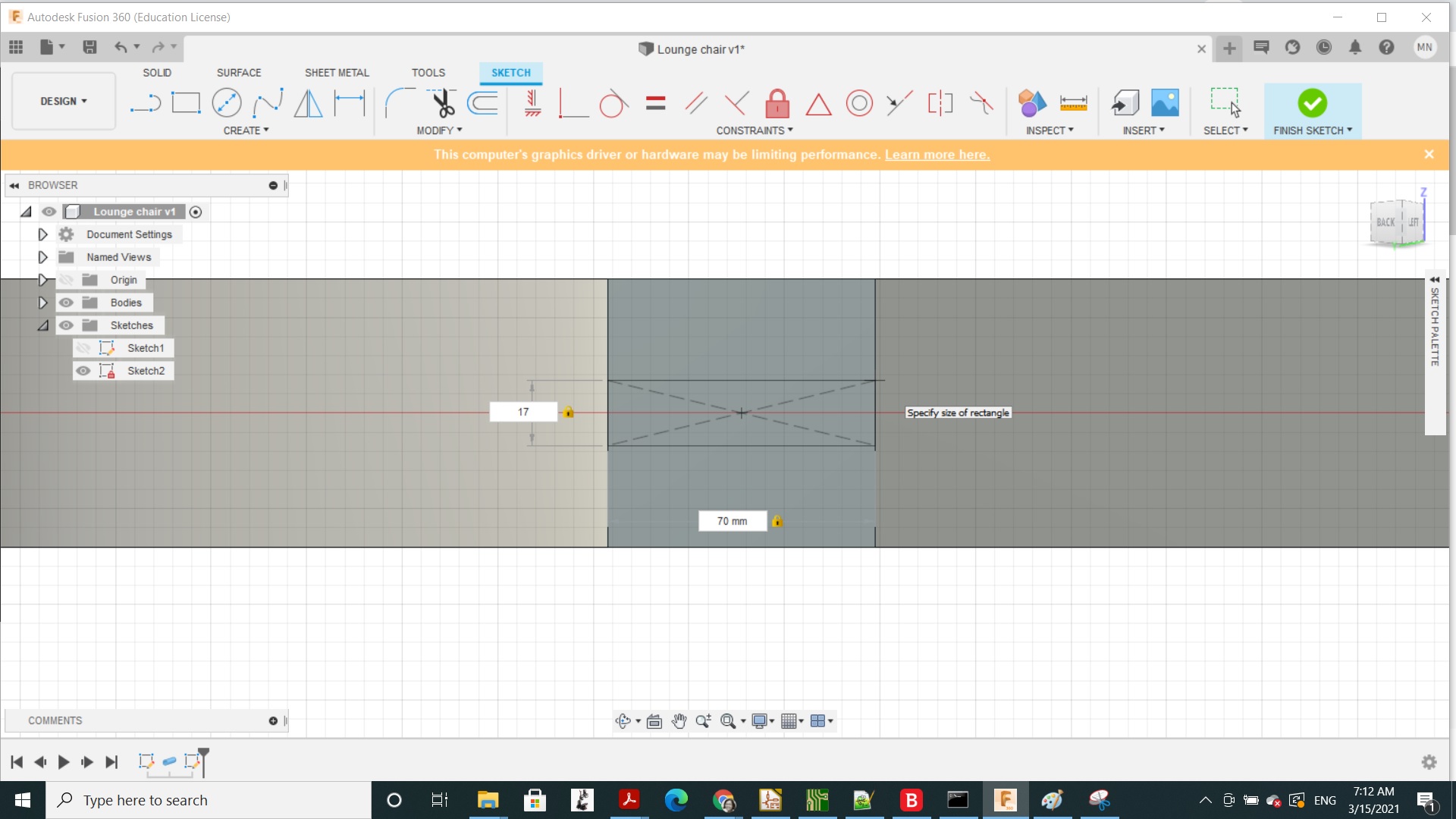
Next we will add holes where support bars that insert into into the two main frames.
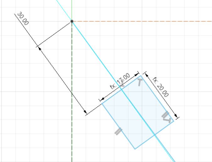
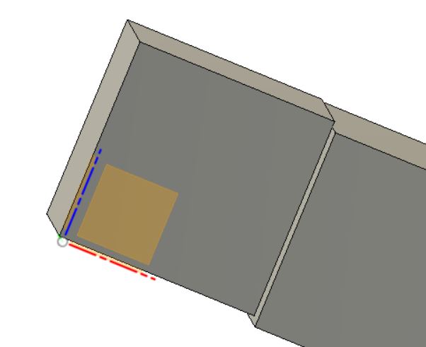
Click on the side bar surface and sketch a rectangle of size thickness. Make it more or less aligned with the spline drawn earlier.
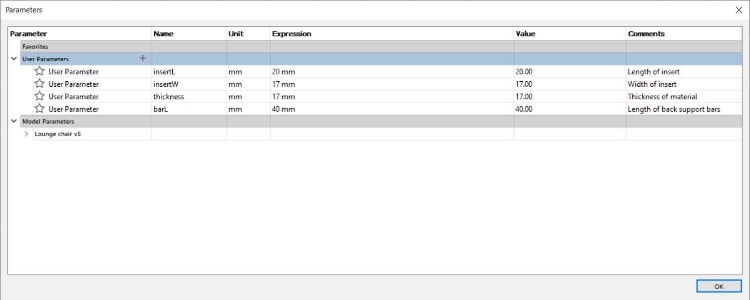
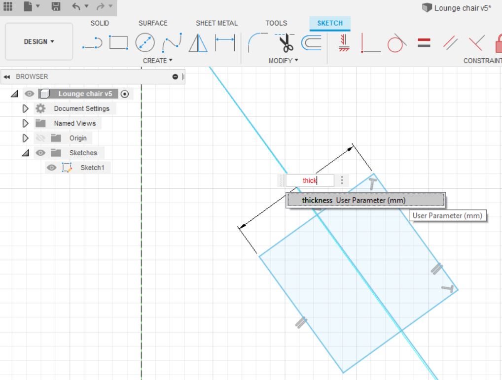
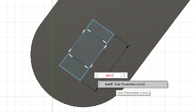
Let’s make some of the dimensions parametric

Proceeding to add dimensions, I start typing the name of a parameter defined in the previous step and click on Fusion360’s suggestion.

Add dogbones
In order for the parts to fit easily, I add dogbones to each hole. Before that, I defined an extra parameter for the diameter of the tool that will make the dogbones.

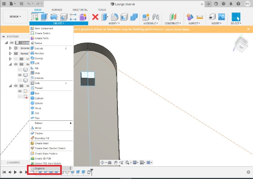
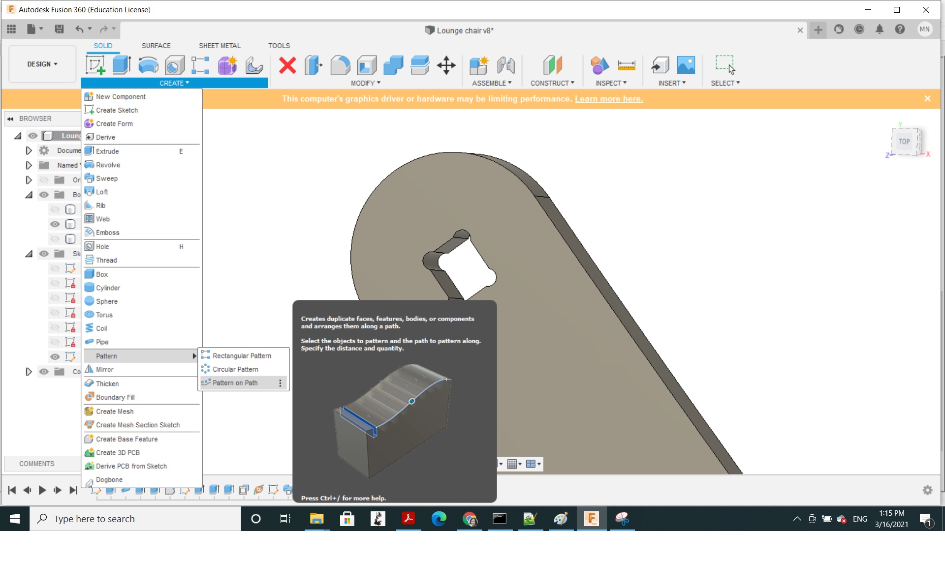
Let’s call the Dogbone add-in that was added earlier from Create menu. Scroll down to the bottom to select Dogbone.
In Dogbone window, select the hole surface and type in toold in Tool diameter.
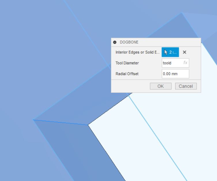
Dogbones are immediately generated but they come with an error message: “Failed to solve. Please revise dimensions or constraints.”
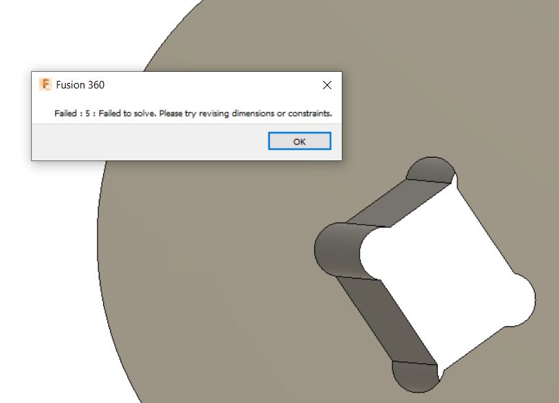
Click Ok ànd again Ok on the next messeage. Ignore the errors.
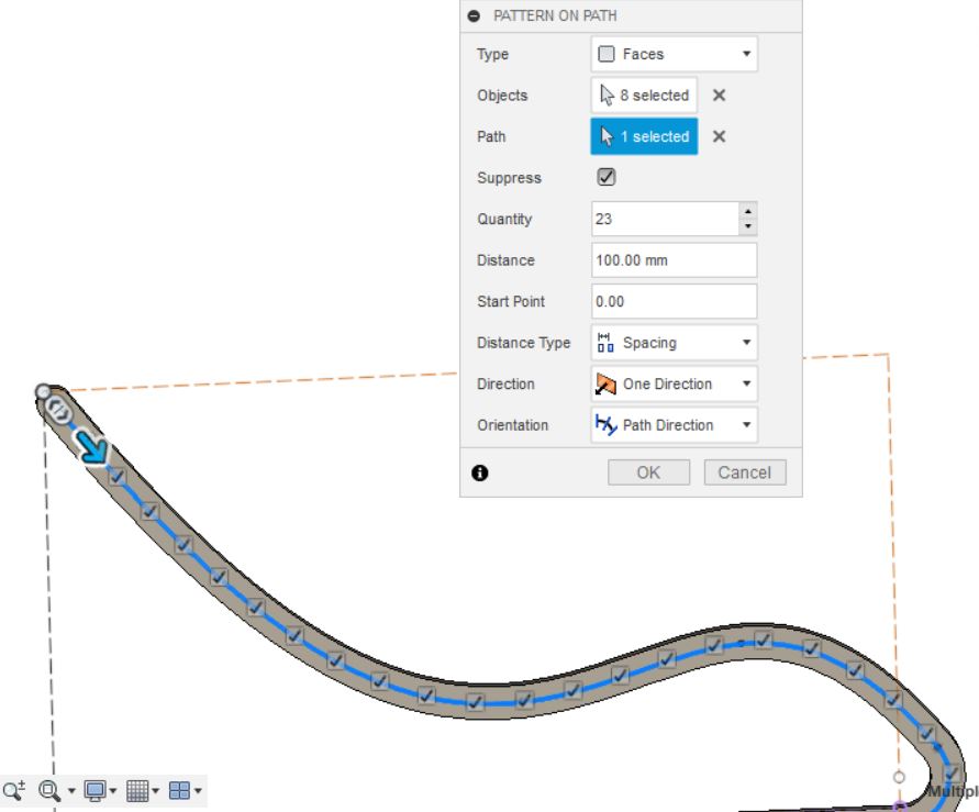
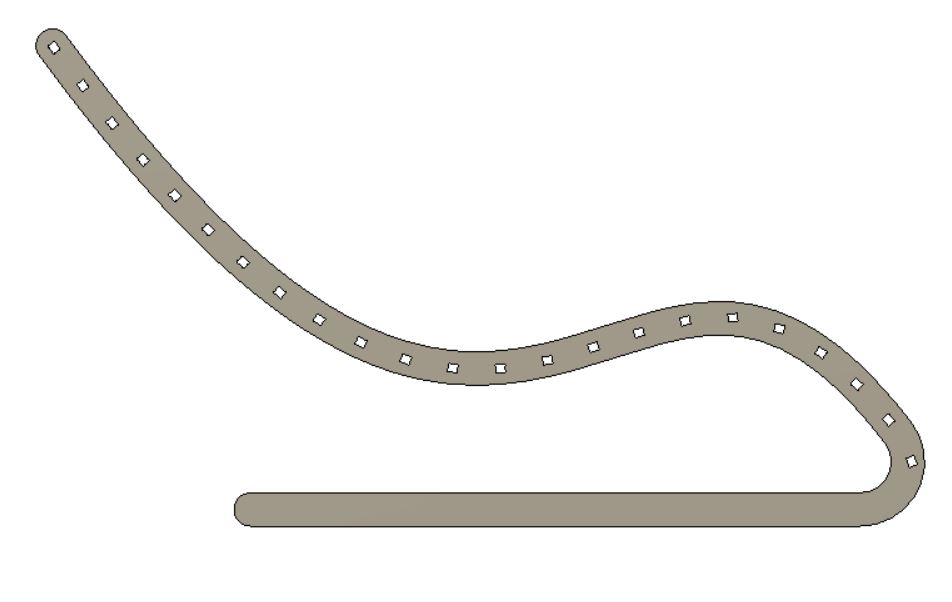
Let’s multiply the holes along the skeleton path by using Create pattern.
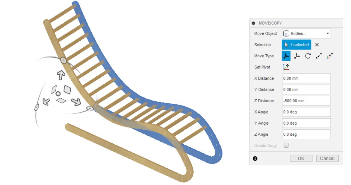
Add back-supporting bars
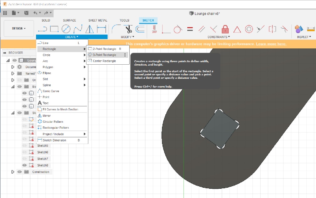
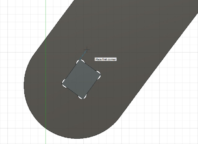
Next we can make back-supporting bars that plug into these holes. Select the inner face of the skeleton and create a 3-point rectangle sketch
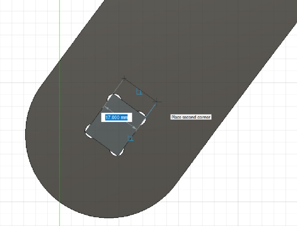
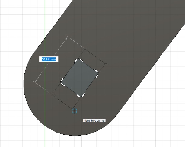
We need to define the dimensions of the rectangle. Add barW as a parameter for the width of the support bars.
The distance between the edges of the insert hole and the rectangle is (barW-insertL)/2
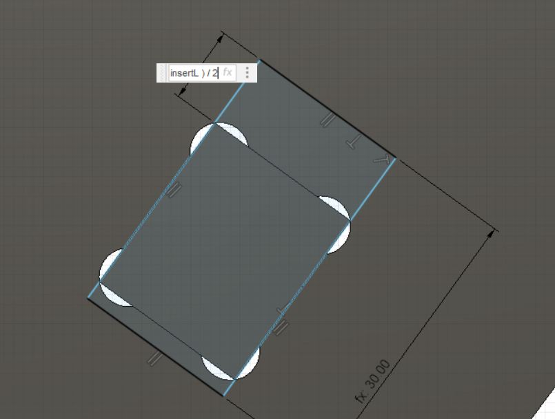
Our rectangle is now symmetrically positioned across the hole.

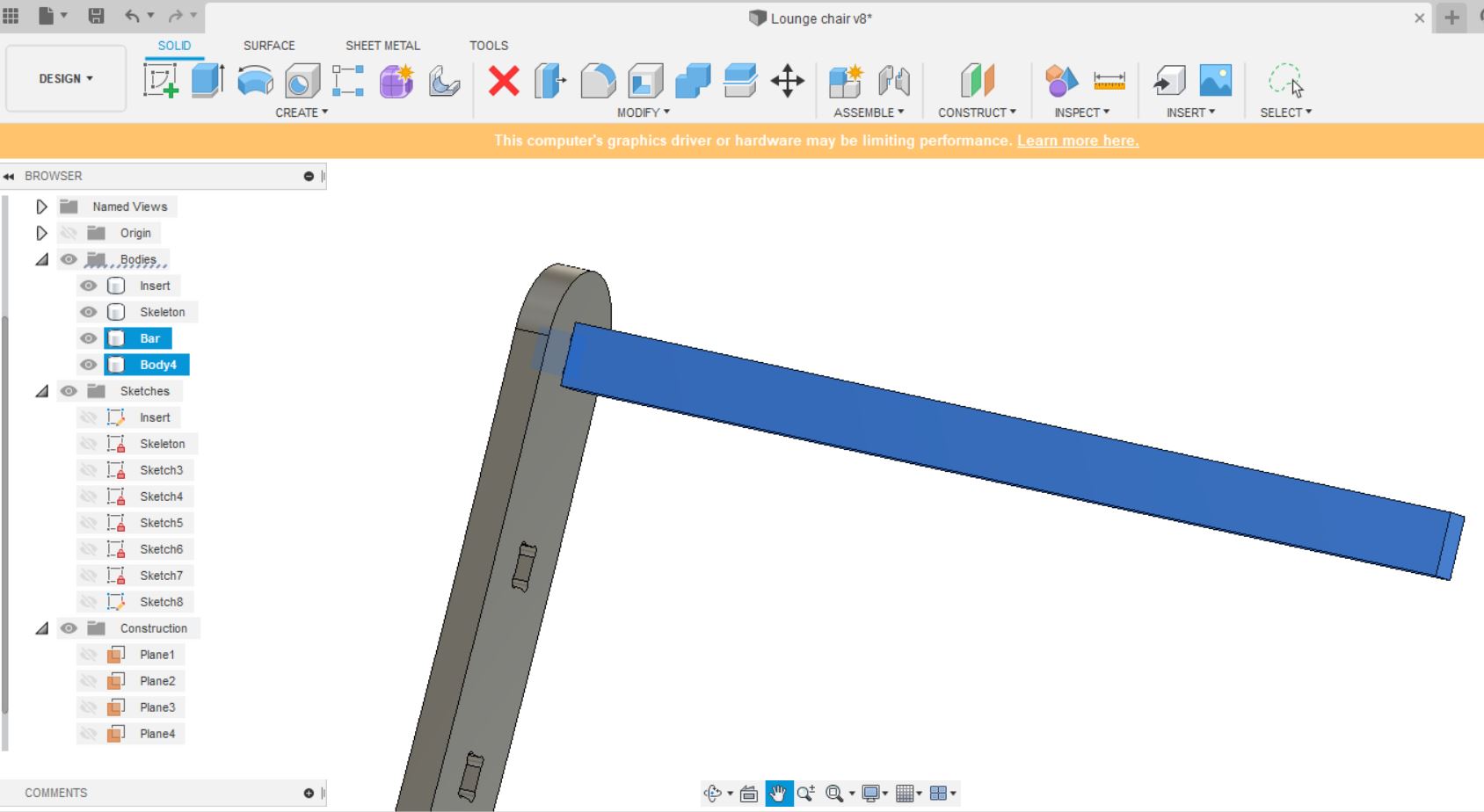
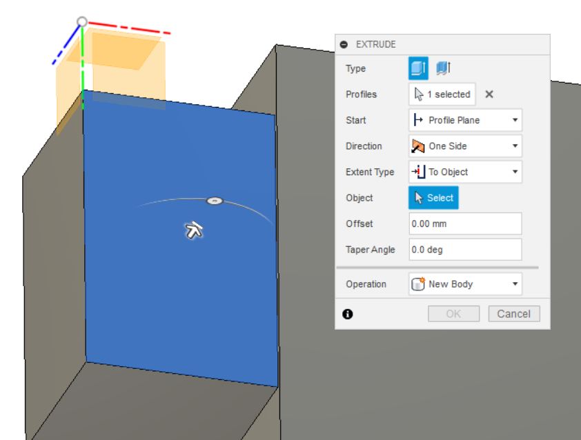
We will extrude the rectangle surface as a new body. Change the parameter for the length of the bar to 500mm.
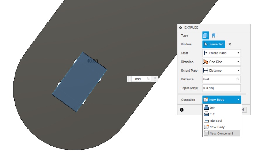
The result looks like this
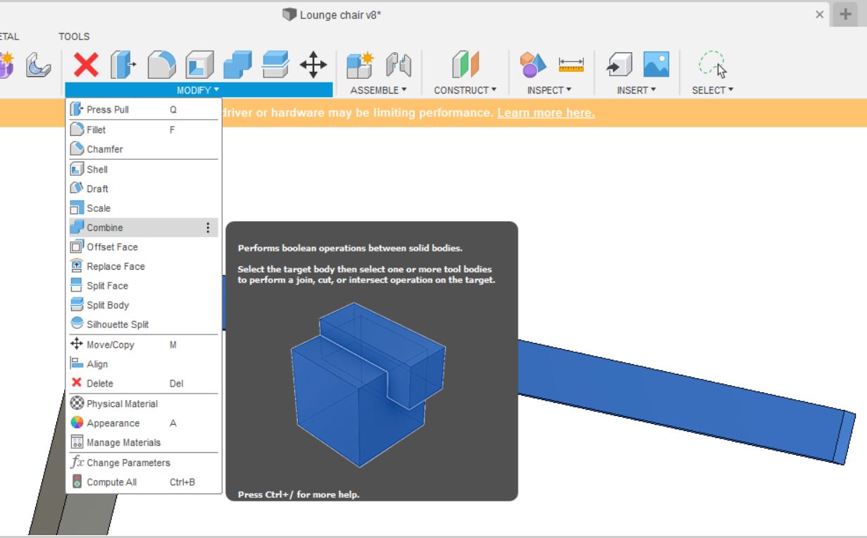
I then combine the insert and the newly extruded body to make a new component.
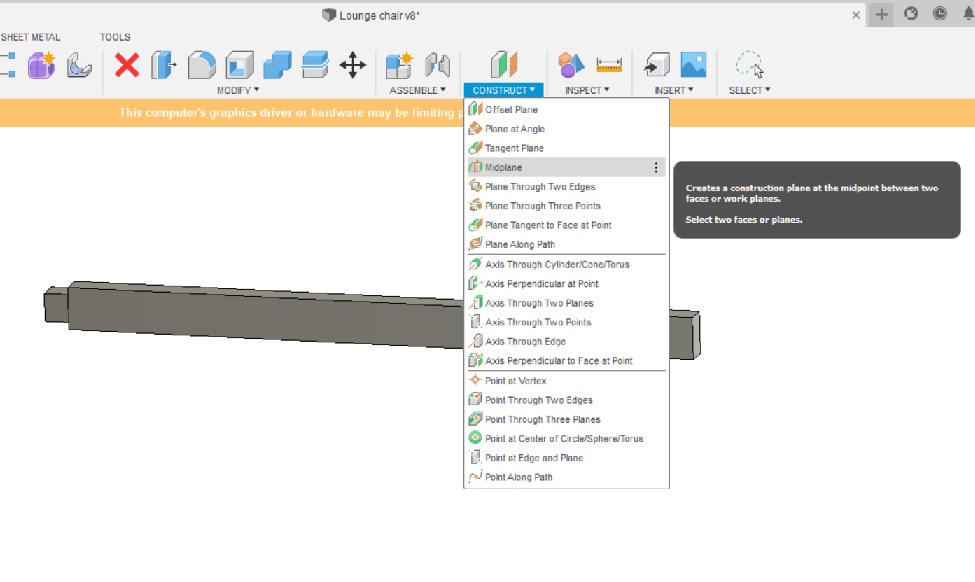
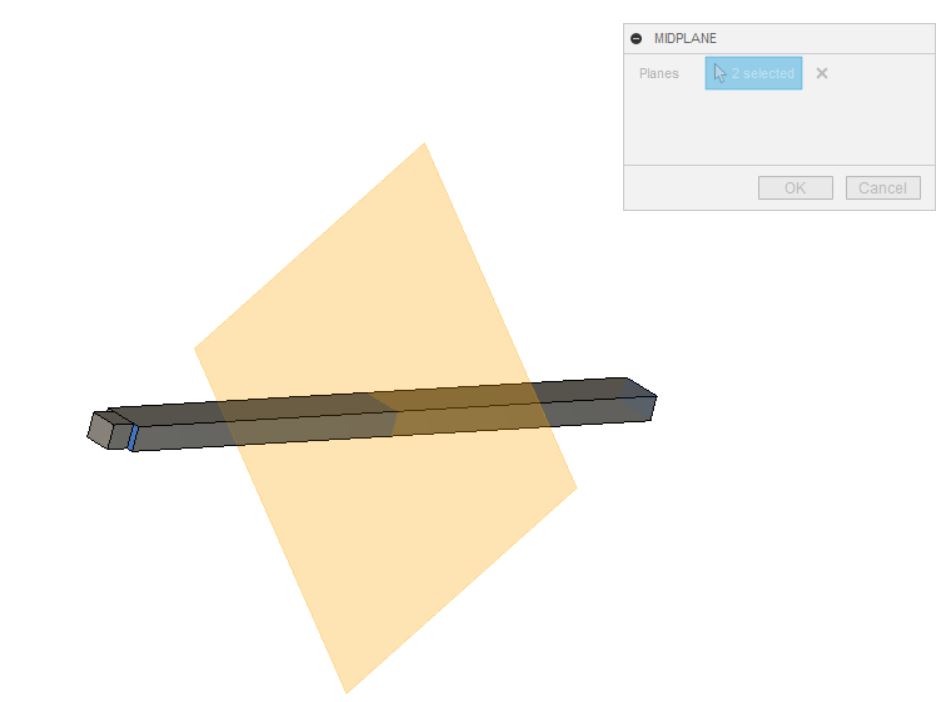
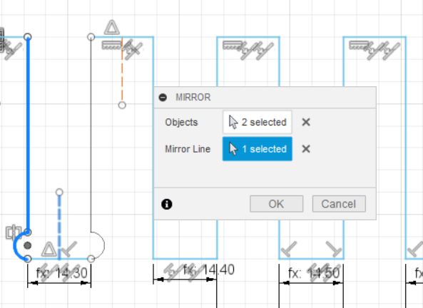
To add an insert body on the other side of the bar, we will do a mirror operation. But first, we have to add a mirror plane.
I performed a mirror operation.
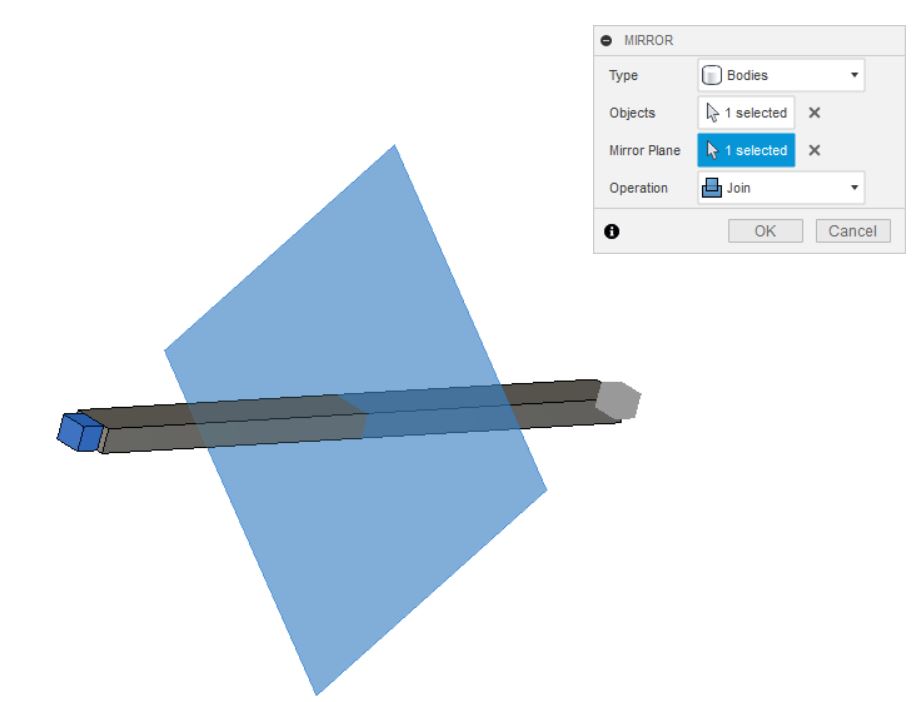
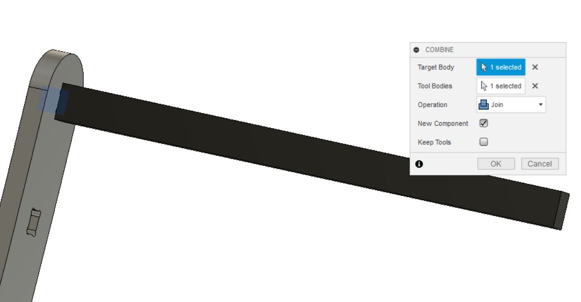
Finally I joined the mirrored body and the bar component.

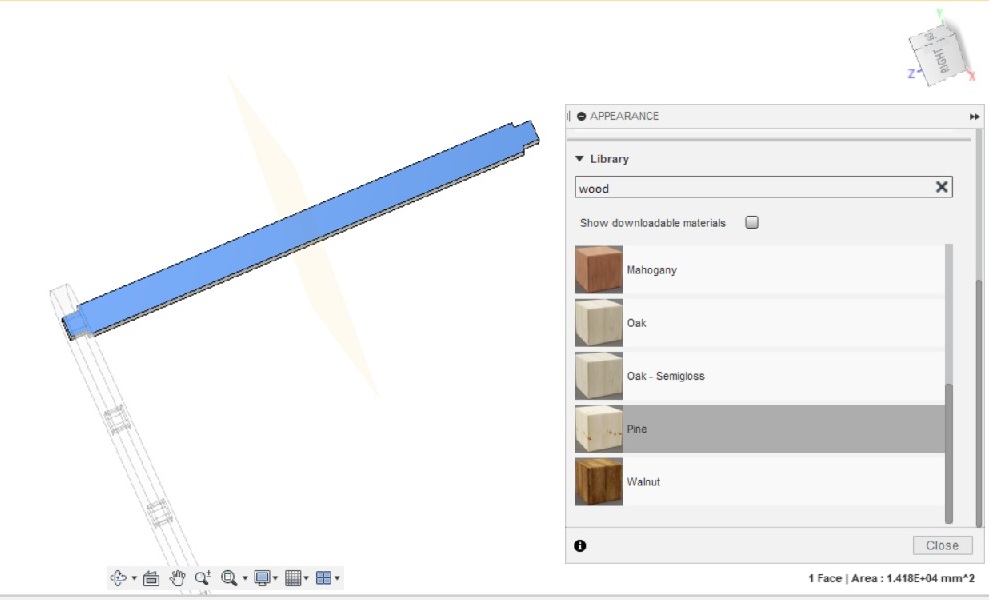
Before making multiple copies of the supporting bars, I changed its appearance to wood.
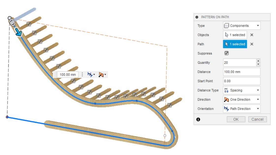
Similar to the dogbone operation, the bars can be added by creating a pattern on path.


Add opposite frame
Last but not least, the chair can only be completed by adding a copy of the skeletal frame on the other side.
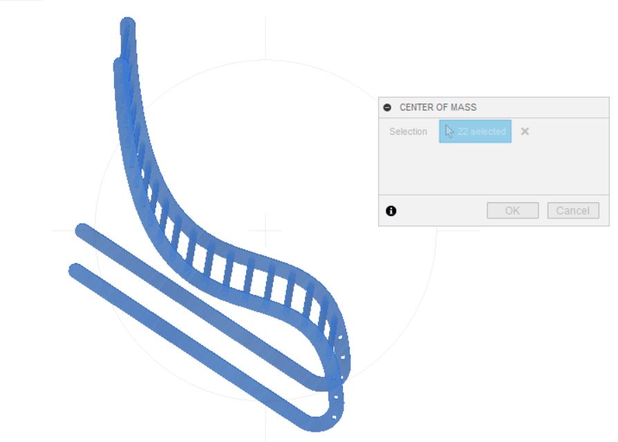
Center of gravity check
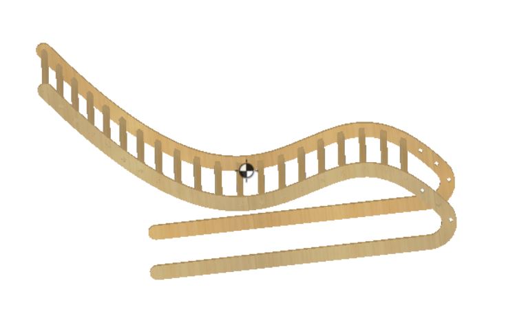
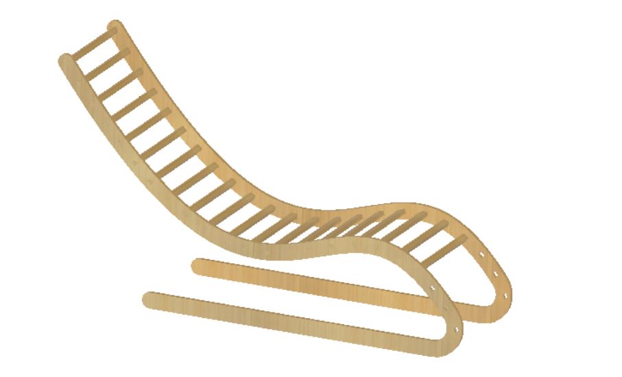
Final chair
The design is now complete and ready for machining.
Actually I think with the normal plywood I will be using, this chair may risk breaking off easily. It probably needs some diagonal support at the bottom to hold up the center of gravity.
Last minute re-design
Due to a miscommunication with the machine owner, the machine’s working area is smaller than initially thought. I had to downsize the chair to be able to fit in a work area of 900 x 1400mm. As a result, it is now less of a “relaxing” chair.
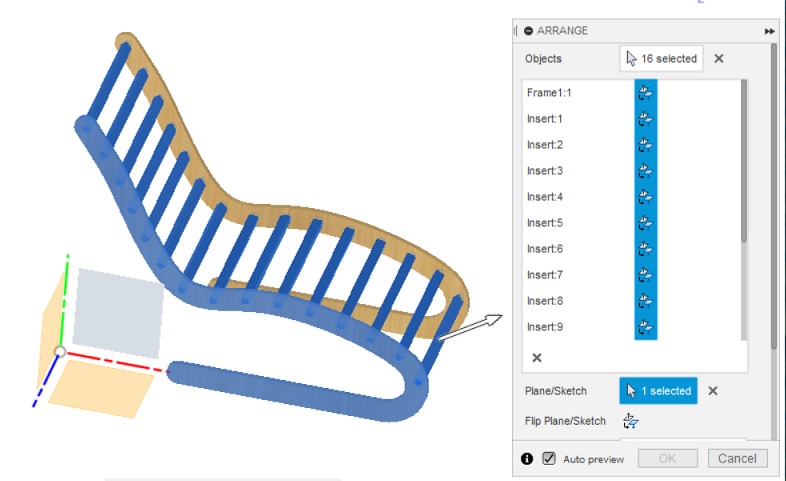
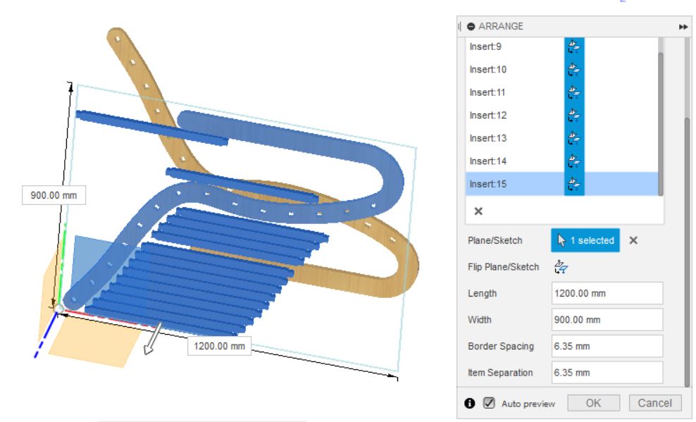
Arrange parts for machining
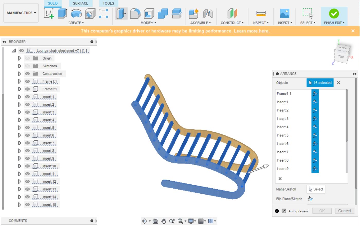
We want to optimize the use of material, which, in this case, is a flat plywood sheet. To do so, I made use of Fusion360’s Arrange feature in Manufacture menu.
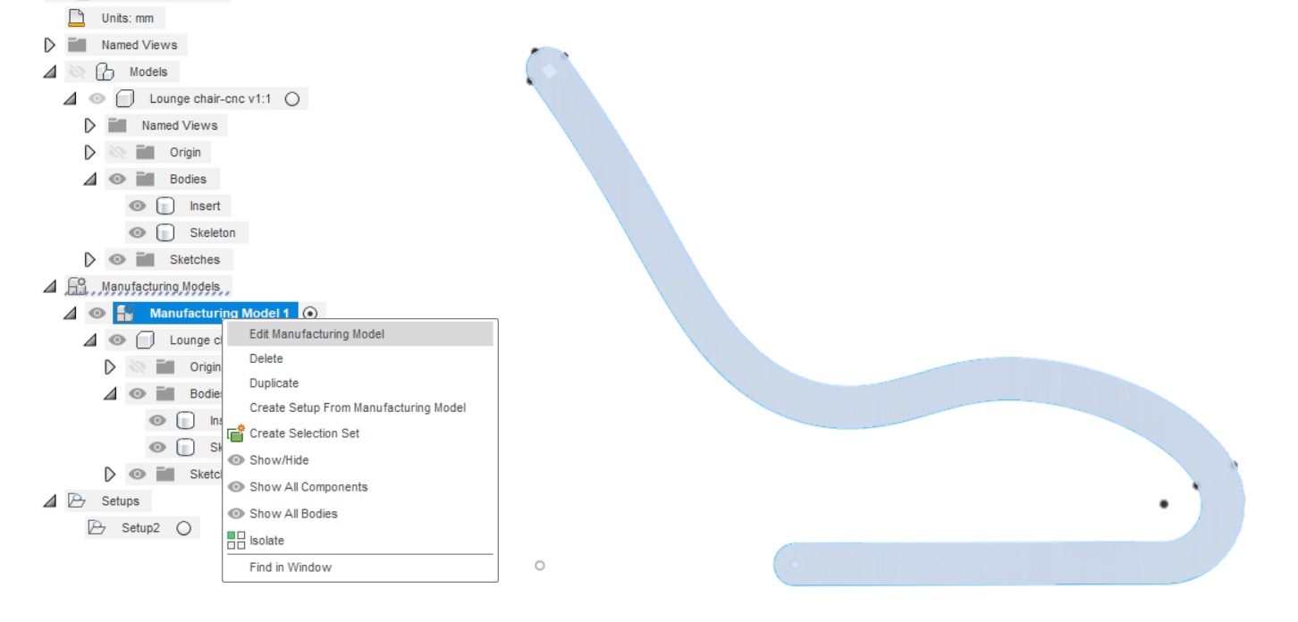
Create a manufacturing model
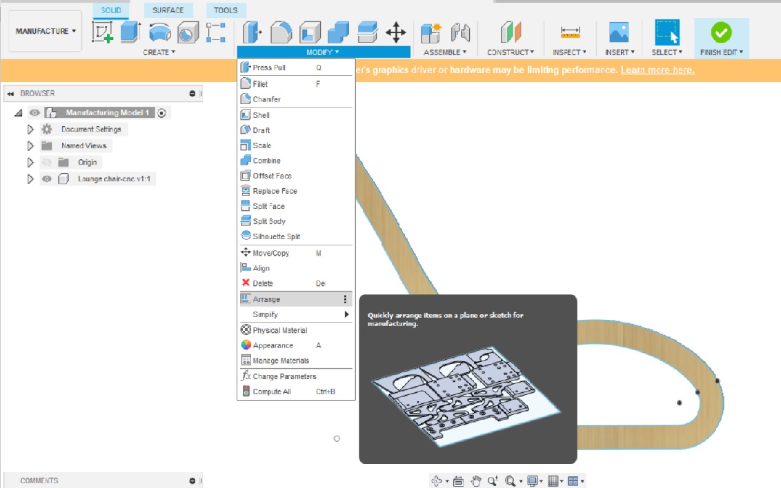
For this, we proceeded to the Manufacture workspace, and create a manufacturing model. Subsequently, I clicked the Arrange function under Modify pane.
![]()


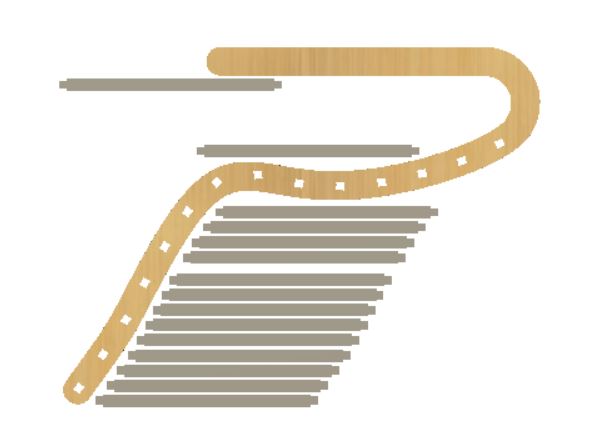
Explore nesting feature
To see if Fusion360 can arrange parts more tightly, I created a nesting study.
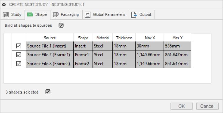
In the nesting suggestions, I was surprised to see that the two legs went missing. Having noticed a yellow exclamation mark next to the Nest Study, I hovered the mouse on it and saw that the two legs are too large to be included in the nest study.
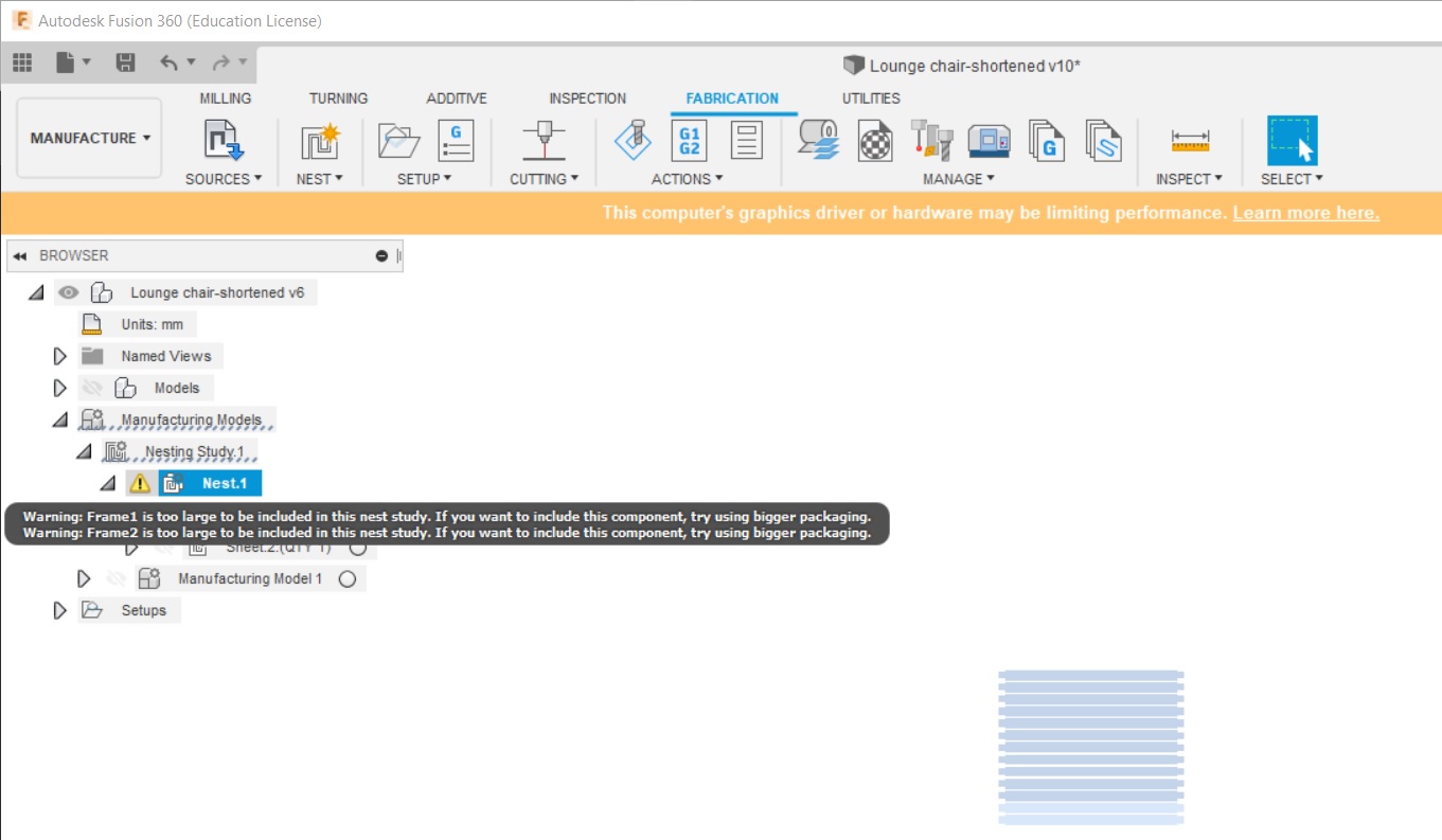
To resolved the said issue, we need to increase the packaging size. However, let’s save it for when more time is available.
Set up a milling operation
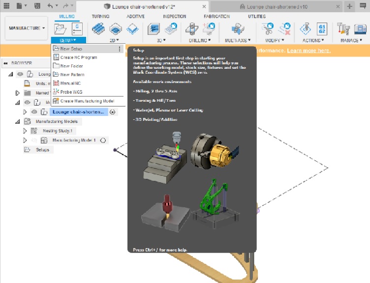
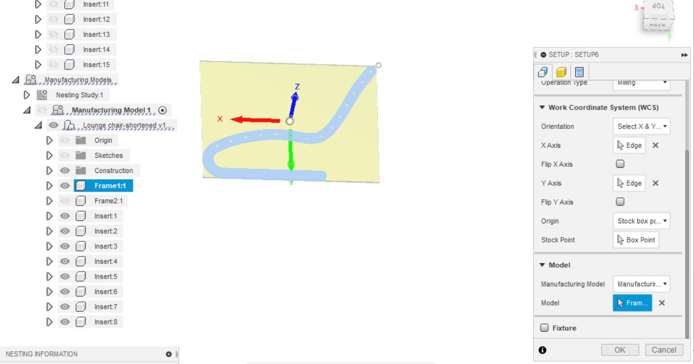
On Setup tab, I used the follow settings:
Work Coordinate System section
- Orientation: Select X&Y; Select edges that align with desired X and Y directions
- Origin: model origin;
- Stock point: box point;
Manufacturing section
- Manufacturing Model: Manufacturing Model 1 (i.e. the one arranged on a flat sheet)
- Model: Click and select a body under Manufacuring model
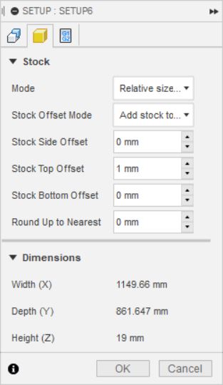
On Stock tab, I used the follow settings:
- Mode: Relative size box
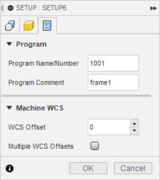
On Program tab, input the followings and press OK.
- Name your program
- Add comments if desired
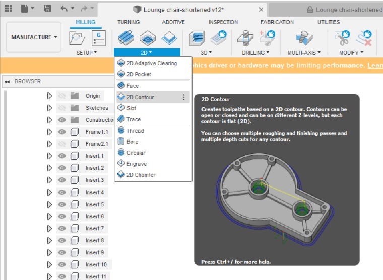
Next, click on 2D menu at the top and select 2D Adaptive Clearing
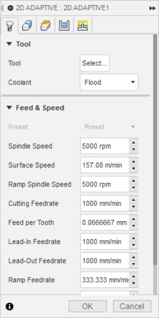
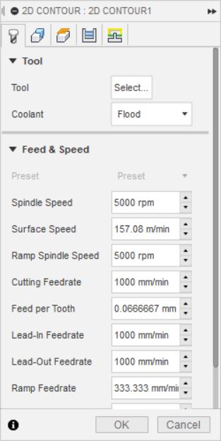
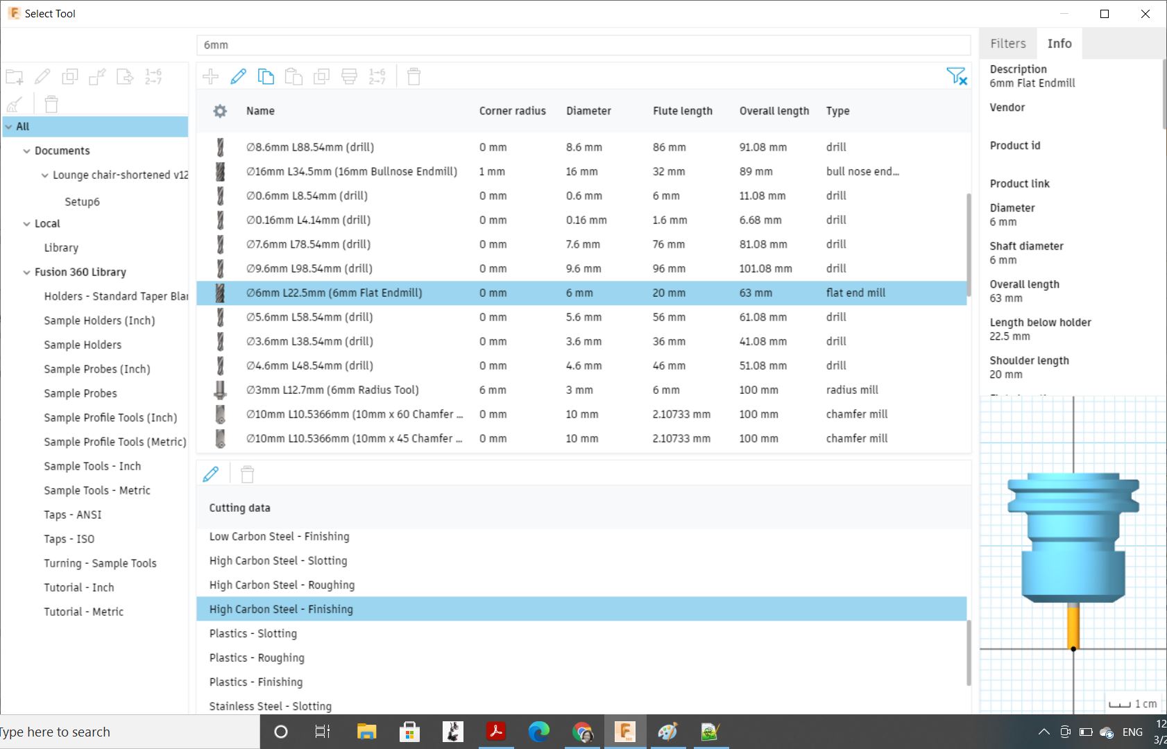
On the Tool tab, I clicked on Tool . The Select Tool dialogue opened.
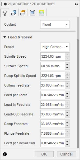
I typed in 6mm which is the diameter of the end mill I would be using. Fusion360 is smart enough to suggest tool presets with 6mm diameter. I selected an appropriate flat end mill type. For Cutting data, I selected High Carbon Steel - Finishing. Press Select.
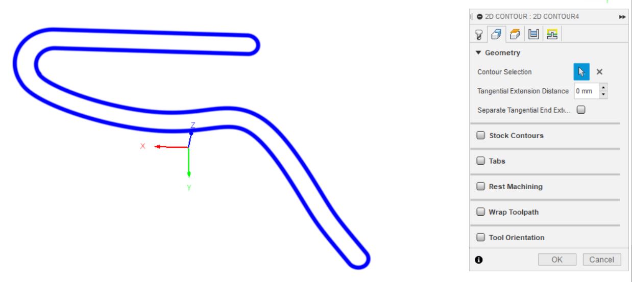
On the Geometry tab, I click on a sketch to select a contour.
I also configured tabs.
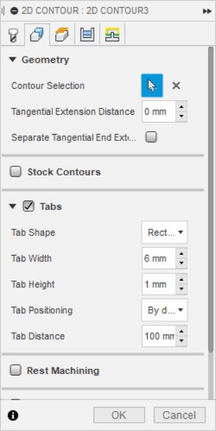
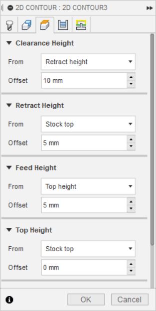
On the Height tab, I went with the default values.
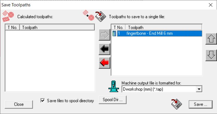
Export gcode
To export gcode from Fusion 360, I followed instructions from this tutorial.
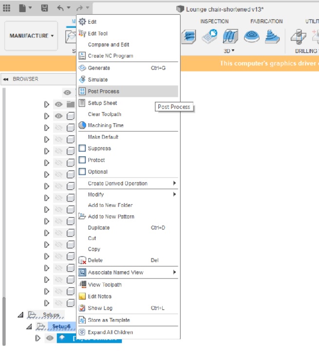
Right click on the 2D-contour operation, and select Post process.
A new dialogue window opened. Select where to save the .tap file.
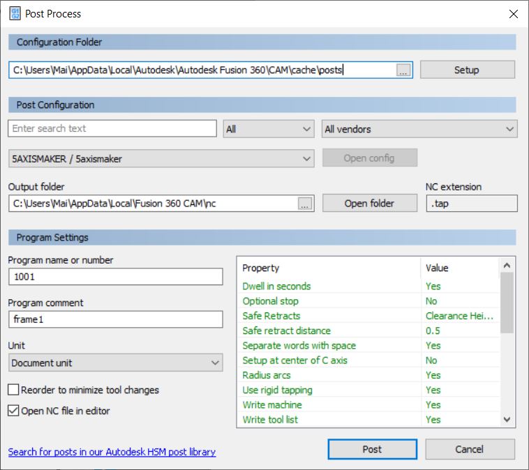
Detailed explanations about this dialogue box are provided by Autodesk here.
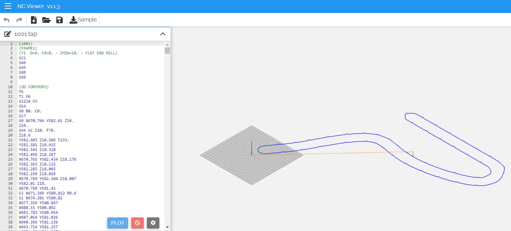
To visualize the saved .tap file, I used ncviewer.
Machining
I could not get access to a big milling machine until a week later than the assignment’s recommended due date. I will update soon.
The legs
Things have been so busy I only had a chance to come see the machine today 6 April.
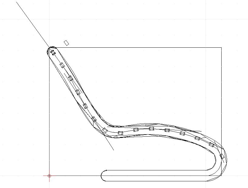
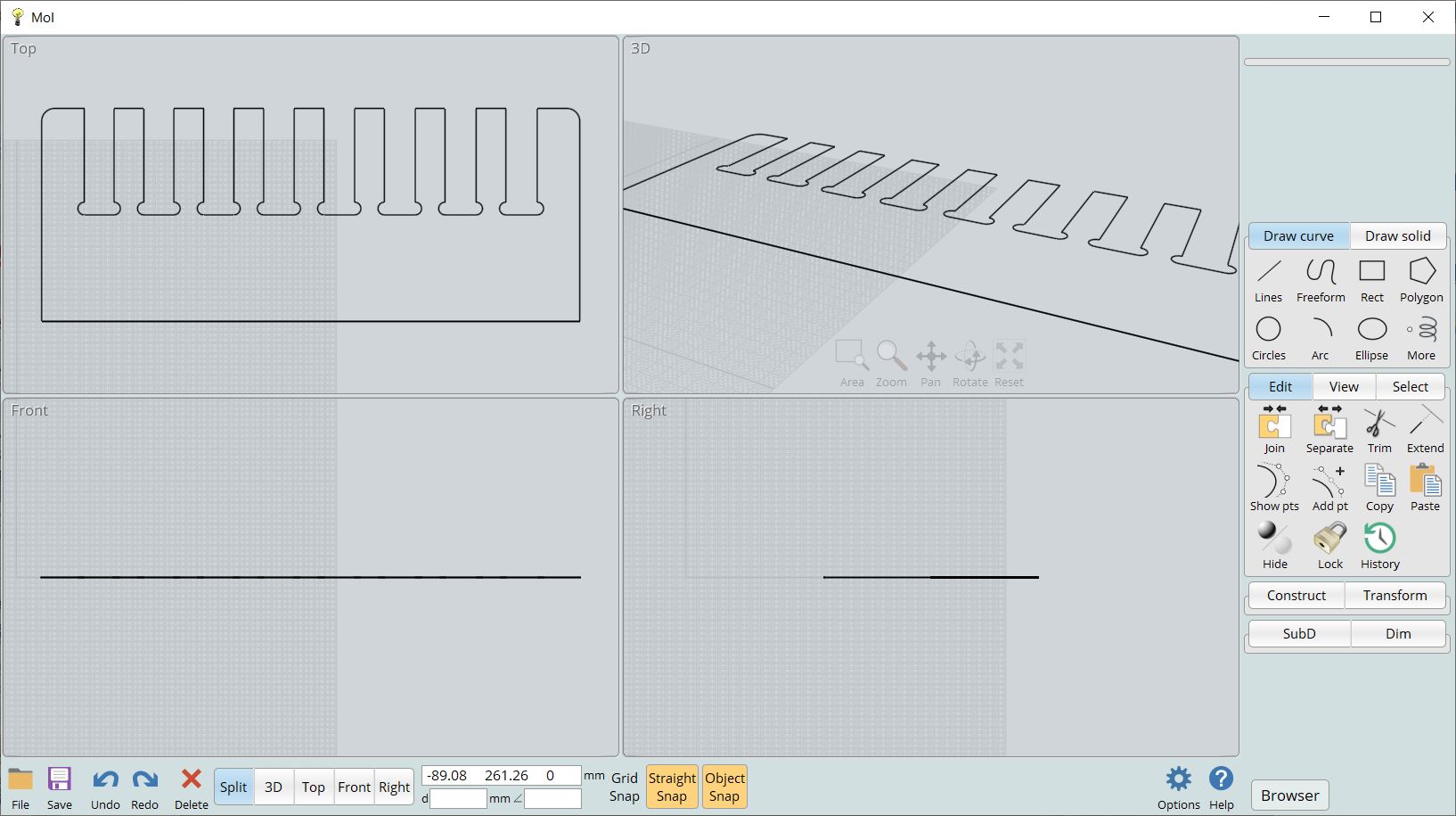
I was ready to open the dxf file exported from Fusion 360 earlier in ArtCAM and make a home run with it. Unfortunately, when I opened the .dxf sketch in QCAD, it looks like a complete mess.
Out of distress, I mentioned the messy dxf issue to my friend Duc who owns the CNC machine that I was about to borrow to mill my piece. He suggested an potential way out.
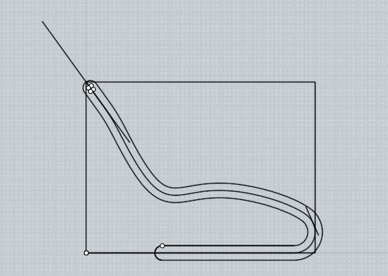
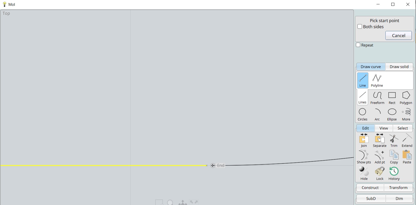
MoI (acronym for Moment of Inspiration) is a handy free software that I had never heard of until my friend told me it could help solve my disconnected vector issue. It is available for free here.

The crossbars
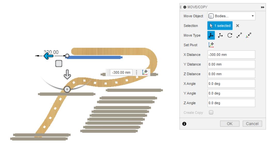
Issue #1: Wrong origin position and orientation
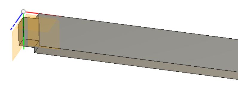
I was trying to export a bar for the first milling test when I discovered that its origin is somewhere far away, not to mention that it also turns on its own axis and not aligned with the coordinate surfaces. This seems to be a common issue but my google search failed to return any straightforward answer. It took me 2 hours to figure out a solution: Using the Align function under the Modify drop-down menu, I managed to align
- the bar’s long surface to the XY plane of the crossbar’s coordinate system
- a short edge and a long edge of the insert body to the X and Y axes of the body origin.
Issue #2: Unflushed surface
The next odd thing I discovered is that the end of the bar seems a little misaligned with the middle part, so I had to do a number of extrusions to make them all flush.

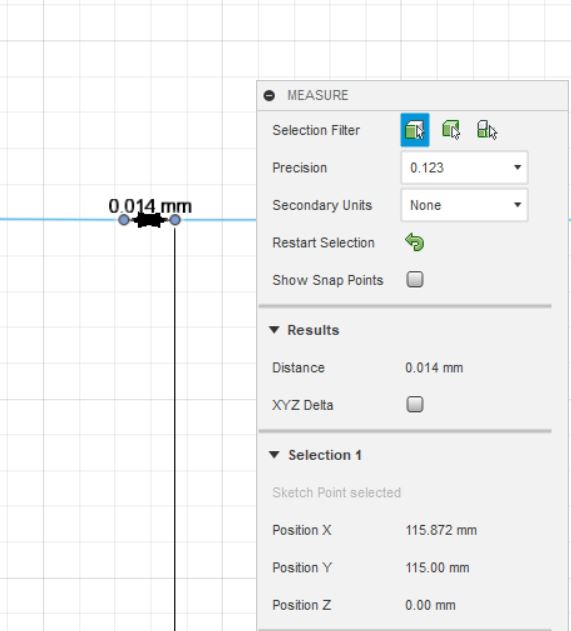
Issue #3: Milling holes

I added two 6mm-dogbone holes to the insert but the toolpath created in Artcam is the same as without the dogbones. To trick the software to mill those two holes, I extended the hole’s diameter to 6.01mm in Moi.
Group assignment
On 6 April, I was able to tackle this assignment.
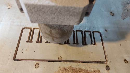
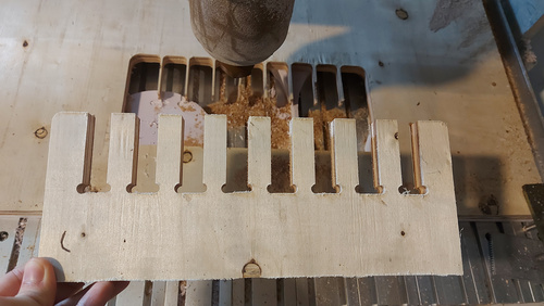
Fingerjoint test
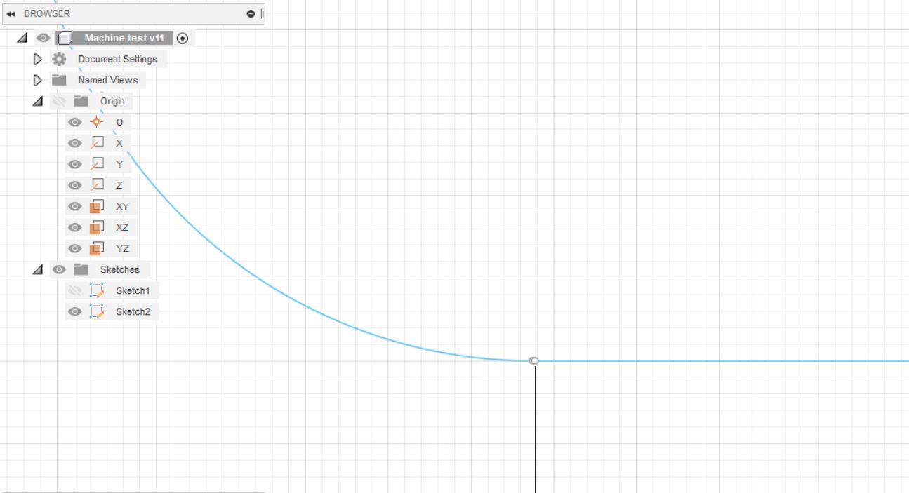
1. Designing in Fusion360
To prepare the cutting file, I created a sketch in Fusion 360 with the intention of porting the vector drawing to ArtCAM.

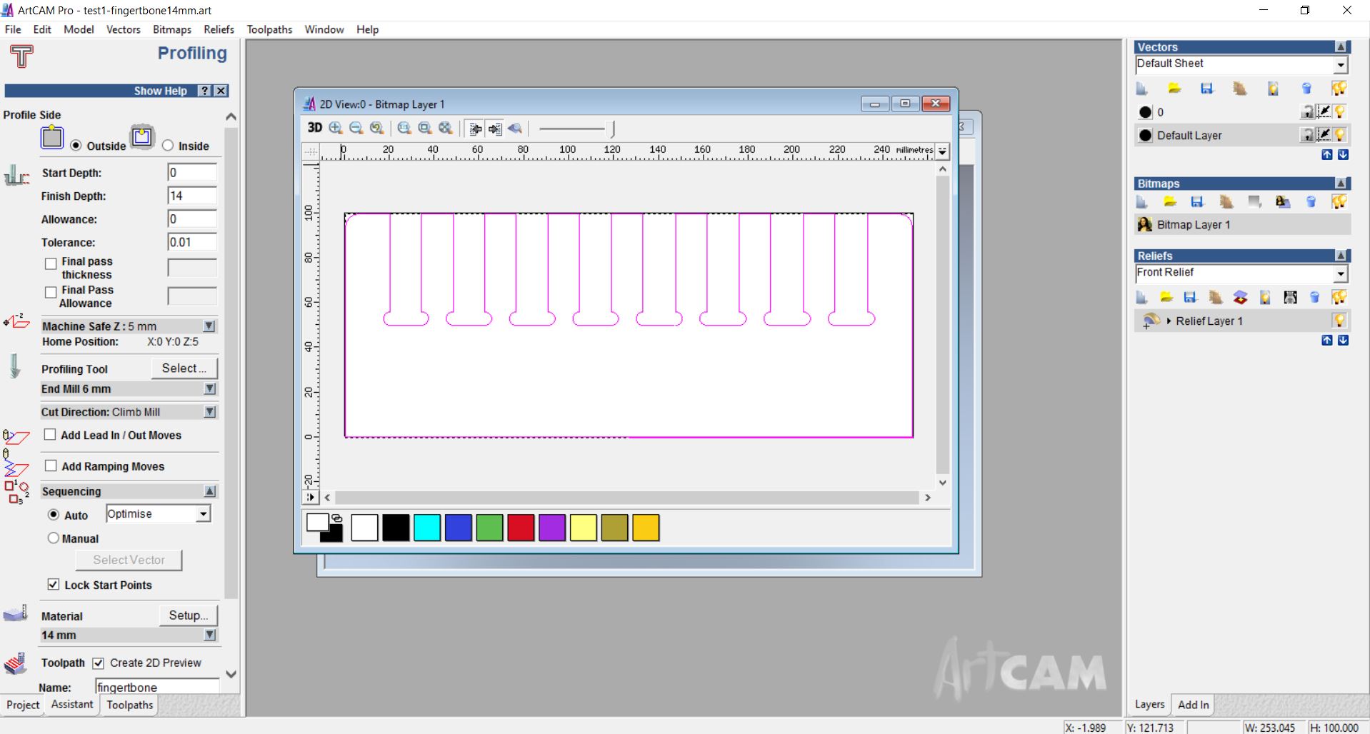
2. Creating a toolpath with ArtCAM
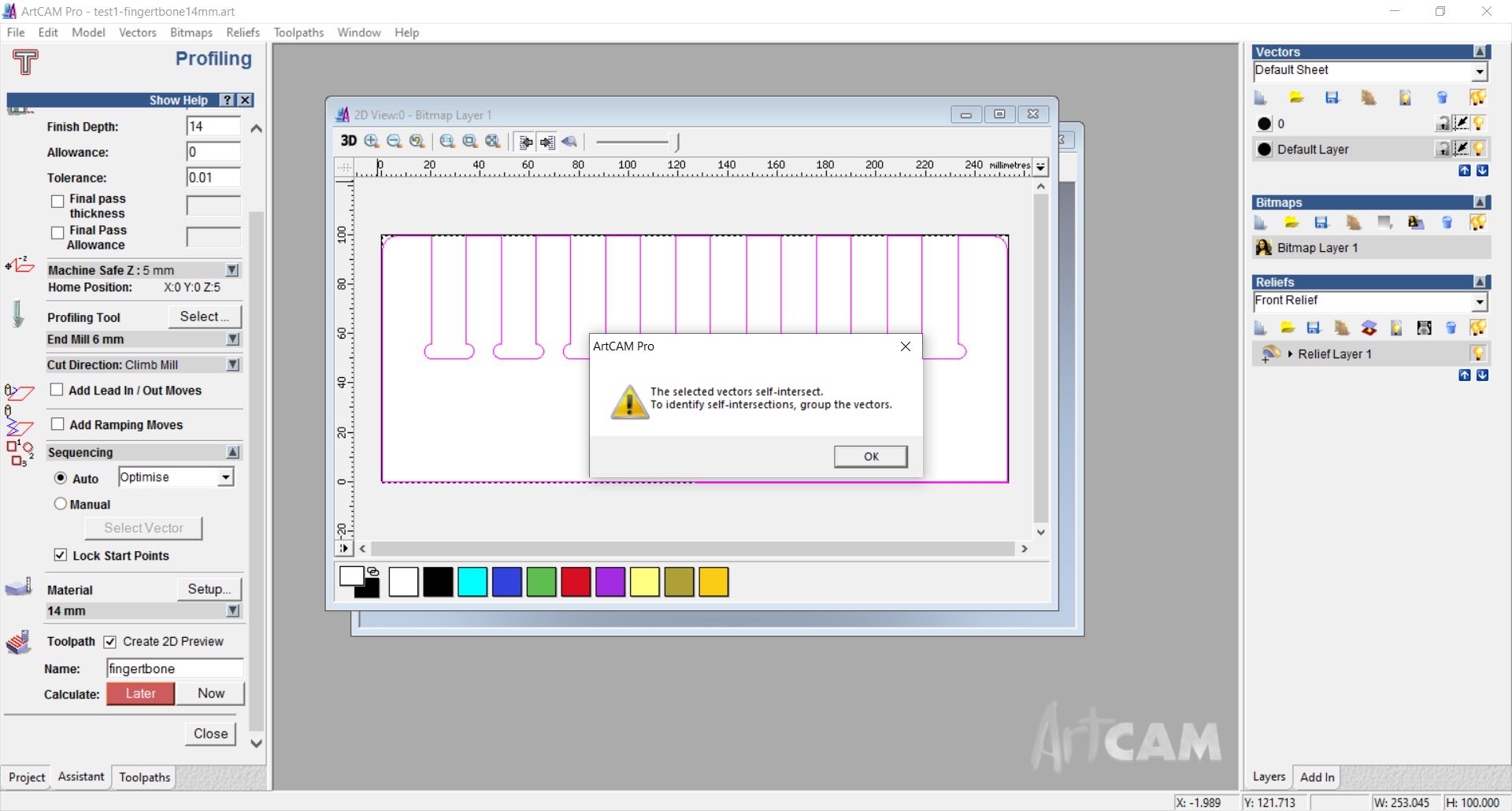
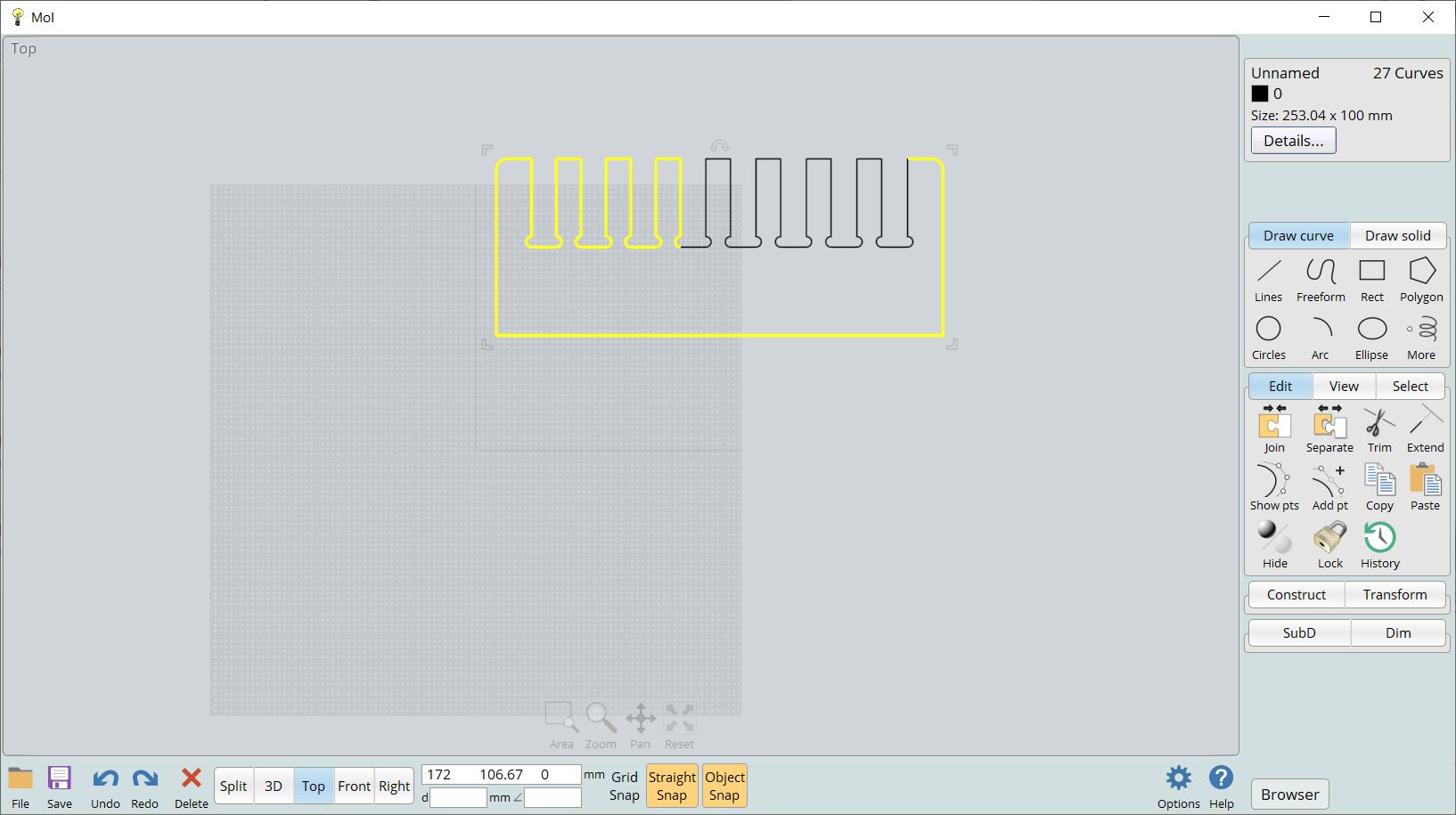
Since ArtCAM could not generate a toothpath, I quickly discovered a broken vector issue. The path exported by Fusion360 was split.
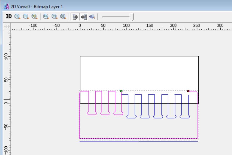
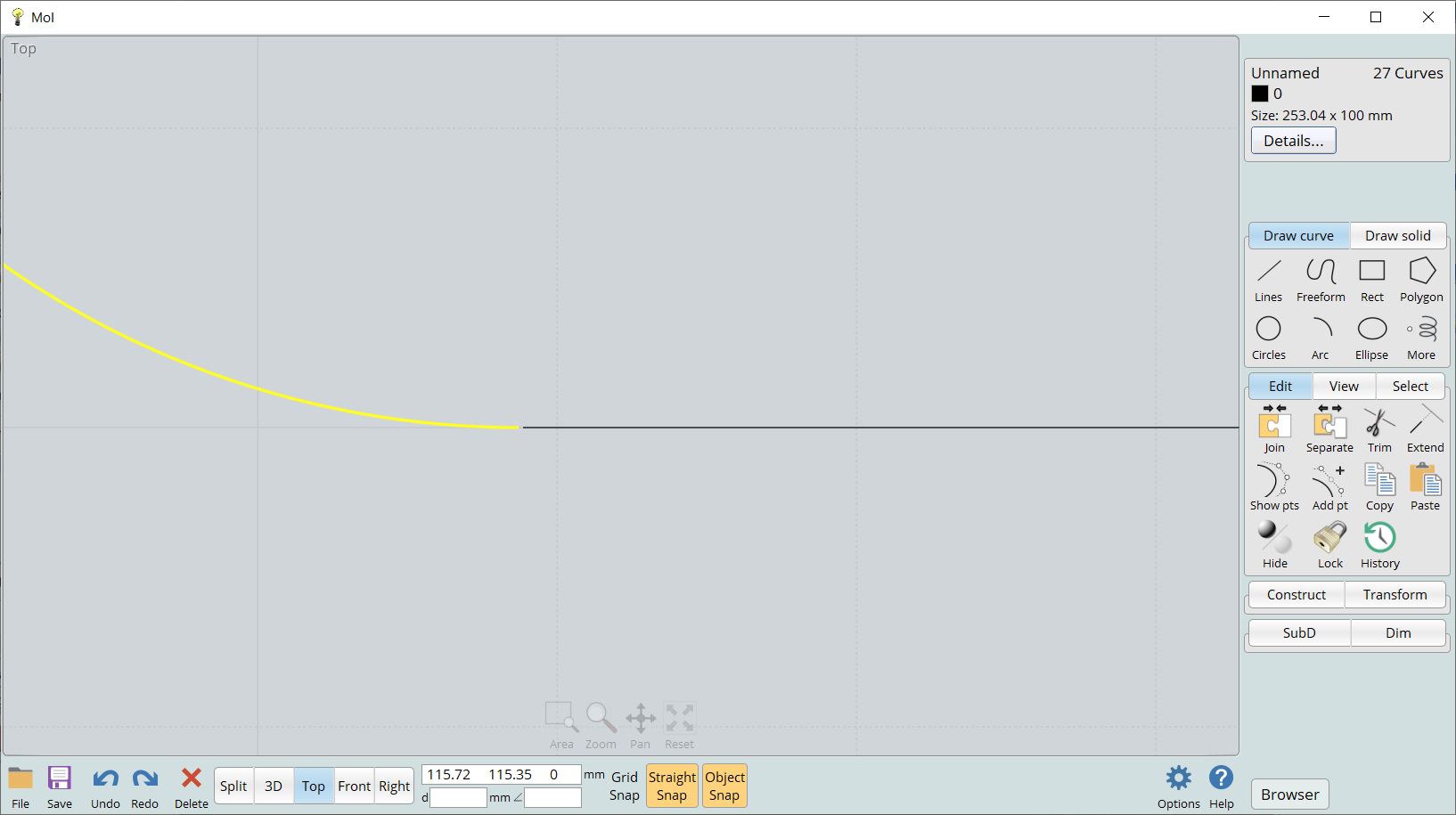
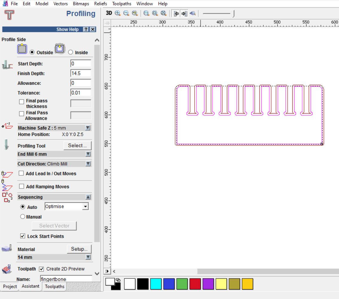
To fix this issue, I used MoI software to join the broken vector. Once done, I was able to obtain a toolpath in ArtCAM which can then be loaded in Mach3.
3. Machinining with Mach3
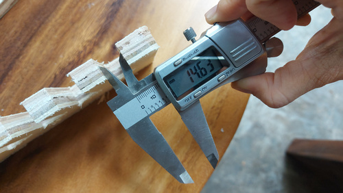
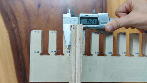
This initial test taught me that the actual thickness of the material is far from being consistent. Although labeled as 13-mm thick in the shop, the material ranges from anywhere between 12mm and 14.2mm. As a result of this, I designed the dogbone holes to be on the lower limit. This is because if the insert happens to be thicker than the hole, it can be easily sanded. On the other hand, if the insert is too thin for the hole, it is more complicated to add material in order to achieve a tight fit.

A summary of my learnings from this assignment
- It took me by surprise that Fusion 360 is terrible at exporting .dxf files, even 5 years after my first attempt to do so. But then MoI came in as a life-saver. It joins nodes so efficiently whereas Fusion 360 takes ages to do.
- Making something big is challenging yet not so difficult once the vector design is in order and the CAM software can interprete it.
- A good workflow from Fusion360 to ArtCAM is to export the 3D file in Fusion360 to .sat format, rather than .dxf, then further process it in MoI software (i.e. stitching disjoint paths), export .dxf and finally import to ArtCAM.
Useful links
- 50 Digital Wood Joints by Jochen Gros
- Dogbone Add-in for Fusion 360
- CAM Milling - 2.5D Fusion 360
- How to export G-code from Fusion 360