14. Output devices
Group assignment
- measure the power consumption of an output device
Individual assignment
- add an output device to a microcontroller board you’ve designed, and
- program it to do something
Hero shot of the week
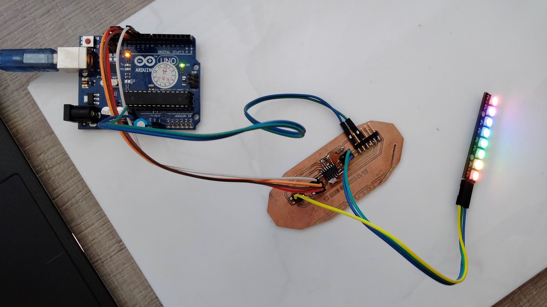
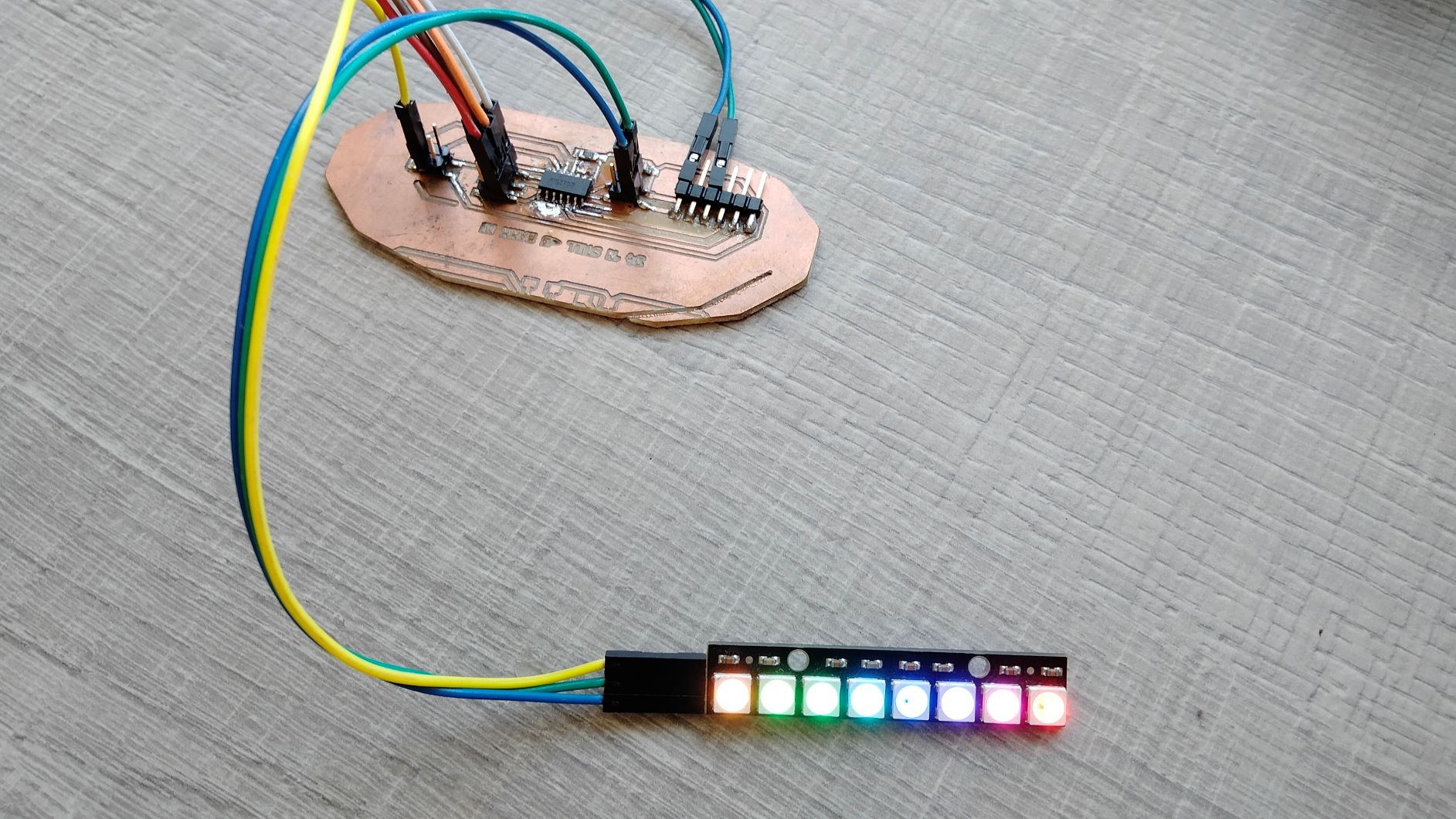 Creating a rainbow effect with LEDs controlled by a self-designed PCB
Group assignment
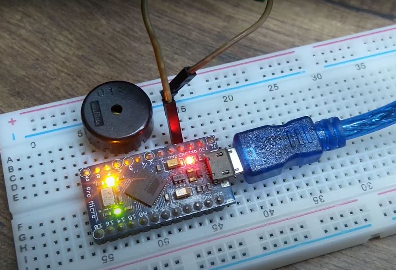
I made a circuit where a piezo-electric buzzer is controlled by an Arduino Micro to play Jingle bells tune.
To measure the power, we need to know voltage and current. Measuring a voltage is straightforward, but to measure current, the multimeter needs to be in series with the buzzer.
This is my circuit for measuring the current
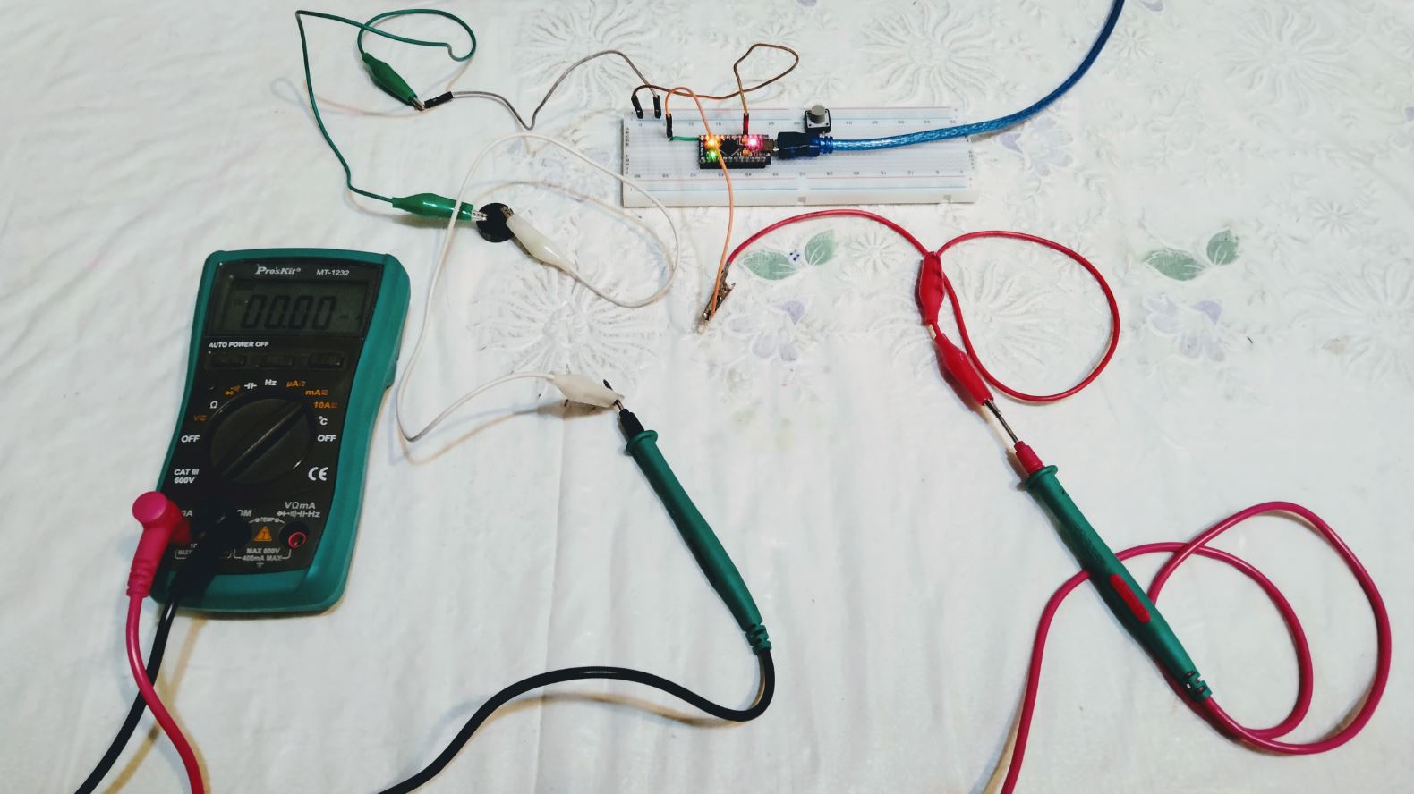
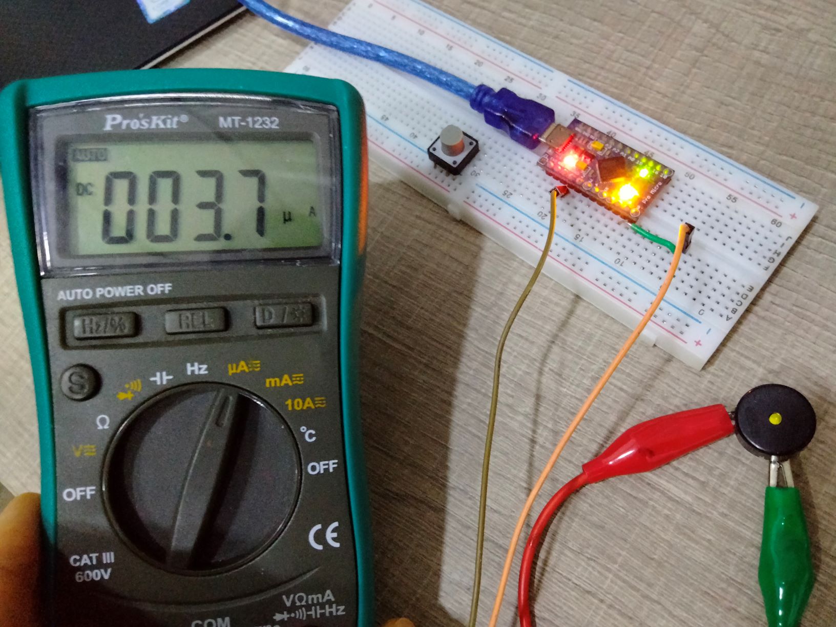
When the buzzer sounds continuously, the current fluctuates between 3.5 and 3.9 micro amps.
Take the average current value I to be 3.7 micro-amps (µA) and multiply it with V which we know to be 5V, and P = I*V = 18.5 micro-watts (µW). This is very little.
In case you are curious how a buzzer works, inside the buzzer is a piezo element, consisting of a central ceramic disc surrounded by a metal (often bronze)vibration disc. When a voltage is applied and varied, the current changes and the ceramic disc either expands or contract, causing vibration, and this vibration makes sounds.
Below is the code.
 // Buzzer plays Jingle bells
 #define  C     2100
 #define  D     1870
 #define  E     1670
 #define  f     1580
 #define  G     1400
 #define  R     0
 int spkOut = 8;
 int DEBUG = 1;
 void setup() {
   pinMode(spkOut, OUTPUT);
   if (DEBUG) {
     Serial.begin(9600);
   }
 }
 int melody[] = {E, E, E,R,
 E, E, E,R,
 E, G, C, D, E, R,
 f, f, f,f, f, E, E,E, E, D ,D,E, D, R, G ,R,
 E, E, E,R,
 E, E, E,R,
 E, G, C, D, E, R,
 f, f, f,f, f, E, E, E,  G,G, f, D, C,R };
 int MAX_COUNT = sizeof(melody) / 2;
 long tempo = 10000;
 int pause = 1000;
 int rest_count = 100;
 int tone_ = 0;
 int beat = 0;
 long duration  = 0;
 void playTone() {
   long elapsed_time = 0;
   if (tone_ > 0) {
     while (elapsed_time < duration) {
       digitalWrite(spkOut,HIGH);
       delayMicroseconds(tone_ / 2);
       digitalWrite(spkOut, LOW);
       delayMicroseconds(tone_ / 2);
       elapsed_time += (tone_);
     }
   }
   else {
     for (int j = 0; j < rest_count; j++) {
       delayMicroseconds(duration);
     }
   }
 }
 void loop() {
  for (int i=0; i<MAX_COUNT; i++) {
    tone_ = melody[i];
    beat = 50;

    duration = beat * tempo;
    playTone();
    delayMicroseconds(pause);
  }
}
Individual Assignment
Since I will use LED strips in the final project, my idea for this week is to program LEDs in such a way that they change colour according to a temperature sensor. For a first step, I will try to program the LED first. I am going to reuse the board that was made for inputs week. It has handy I/O headers to which a LED strip of 8 Neopixels can be easily connected.
Wiring
Fortunately, the LED strip available in our lab already comes with 3 female wire headers (VCC, GND and DIN), making it convenient for me to plug into the headers on my board with ease. To know which pin I should connect to, I referred to this handy pinout mapping from a Fab Academy tutorial.
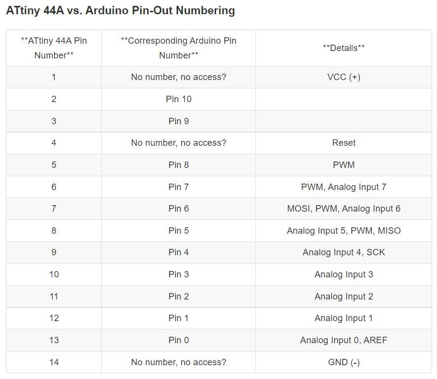
Given my existing PCB design, I have the options of connecting DIN to ATtiny pin 5 or 6 which have PWM to drive the LEDs. I chose pin 6.
Programming
Programming the LED strip requires the use of a library for Arduino IDE named Adafruit_NeoPixel.h. Here are some sample codes
Code by Fabacademy alumni Gleb Bulygin
Bulygin reported that the sketch was too big for ATtiny, I removed everything in the code, keeping only colorWipe function.
// NeoPixel test program showing use of the WHITE channel for RGBW
// pixels only (won't look correct on regular RGB NeoPixel strips).

#include <Adafruit_NeoPixel.h>
#ifdef __AVR__
 #include <avr/power.h> // Required for 16 MHz Adafruit Trinket
#endif

#define LED_PIN     8 //5pin on ATtiny44

// How many NeoPixels are attached to the Arduino?
#define LED_COUNT  15

// NeoPixel brightness, 0 (min) to 255 (max)
#define BRIGHTNESS 50
// Declare our NeoPixel strip object:
Adafruit_NeoPixel strip(LED_COUNT, LED_PIN, NEO_GRBW + NEO_KHZ800);
// Argument 1 = Number of pixels in NeoPixel strip
// Argument 2 = Arduino pin number (most are valid)
// Argument 3 = Pixel type flags, add together as needed:
//   NEO_KHZ800  800 KHz bitstream (most NeoPixel products w/WS2812 LEDs)
//   NEO_KHZ400  400 KHz (classic 'v1' (not v2) FLORA pixels, WS2811 drivers)
//   NEO_GRB     Pixels are wired for GRB bitstream (most NeoPixel products)
//   NEO_RGB     Pixels are wired for RGB bitstream (v1 FLORA pixels, not v2)
//   NEO_RGBW    Pixels are wired for RGBW bitstream (NeoPixel RGBW products)

void setup() {
   strip.begin();           // INITIALIZE NeoPixel strip object (REQUIRED)
  strip.show();            // Turn OFF all pixels ASAP
  strip.setBrightness(BRIGHTNESS); // Set BRIGHTNESS to about 1/5 (max = 255)
}

void loop() {
  // Fill along the length of the strip in various colors...
  colorWipe(strip.Color(255, 0, 0, 0)     , 50); // Red
  colorWipe(strip.Color(0, 255, 0, 0)     , 50); // Green
  colorWipe(strip.Color(0, 0, 255, 0)     , 50); // Blue
  colorWipe(strip.Color(0, 0, 0, 255), 50); // True white (not RGB white)
}

// Fill strip pixels one after another with a color. Strip is NOT cleared
// first; anything there will be covered pixel by pixel. Pass in color
// (as a single 'packed' 32-bit value, which you can get by calling
// strip.Color(red, green, blue) as shown in the loop() function above),
// and a delay time (in milliseconds) between pixels.
void colorWipe(uint32_t color, int wait) {
  for(int i=0; i<strip.numPixels(); i++) { // For each pixel in strip...
    strip.setPixelColor(i, color);         //  Set pixel's color (in RAM)
    strip.show();                          //  Update strip to match
    delay(wait);                           //  Pause for a moment
  }
}
Code by Adafruit
#include <Adafruit_NeoPixel.h>

#define LED_COUNT 8
#define LED_PIN   8

Adafruit_NeoPixel strip(LED_COUNT, LED_PIN, NEO_GRB + NEO_KHZ800);

void setup() {
  strip.begin();
  strip.show();
  strip.setBrightness(50);
}


void loop() {
  rainbow(10);
}

void rainbow(int wait) {
  for(long firstPixelHue = 0; firstPixelHue < 5*65536; firstPixelHue += 256) {
    for(int i=0; i<strip.numPixels(); i++) {
      int pixelHue = firstPixelHue + (i * 65536L / strip.numPixels());
      strip.setPixelColor(i, strip.gamma32(strip.ColorHSV(pixelHue)));
    }
    strip.show();
    delay(wait);
  }
}
To make things simple, I went with Adafruit’s program and made sure that the LED_PIN was changed to 7. Similar to Inputs week, using Arduino as ISP, I succesfully flashed it to the ATtiny.
![]()
![]()
Once flashed to my board, the LEDs did not light up at all, despite having a 5V voltage supply. I suspected that pin 7 needs specific configuration before it can perform the PWM function, since it can also be used as an analog input pin. Thankfully, I still had access to pin 8, which only has PWM function and nothing else. With LED_PIN changed to 8, it worked immediately!
In my final project, I will be controlling about 200+ LEDs so this small exercise is a good preparation for that. At the beginning, I wanted to make the LEDs change colour according to a temperature probe, for example, the LEDs will glow red when it’s hot and blue when it’s ice-cold. Unfortunately, time was running out and I could not test further.