13. Molding and casting
This week I worked on defining my final project idea and started to getting used to the documentation process.
Group assignment
- review the safety data sheets for each of your molding and casting materials,
- then make and compare test casts with each of them
Individual assignment
- design a mold around the stock and tooling that you’ll be using,
- mill it (rough cut + (at least) three-axis finish cut), and use it to cast parts
Hero shots
Group assignment
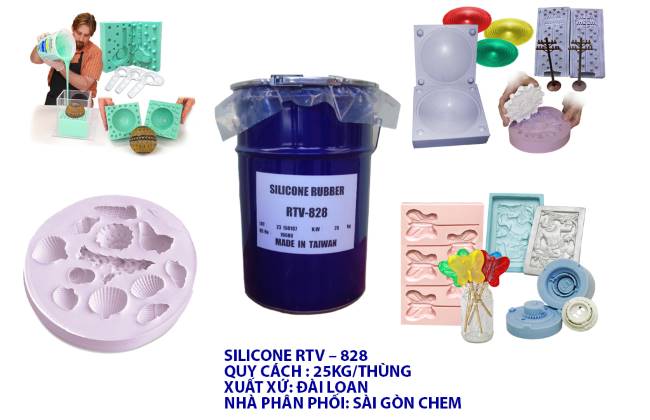
In Vietnam, Taiwanese silicons are most commonly available, and they go by the names of RTV-828 and RTV-528. Distributors hardly provide safety datasheets for them, and only share some specifications on the website.
Thinking of making a mold that can be used for either chocolate or ice-cubes, I ordered a clear and supposedly food-grade silicon rubber from Lazada. Unfortunately the seller did not respond on the day where they are supposed to deliver, so I had to cancel and order from another one which caused a delay.
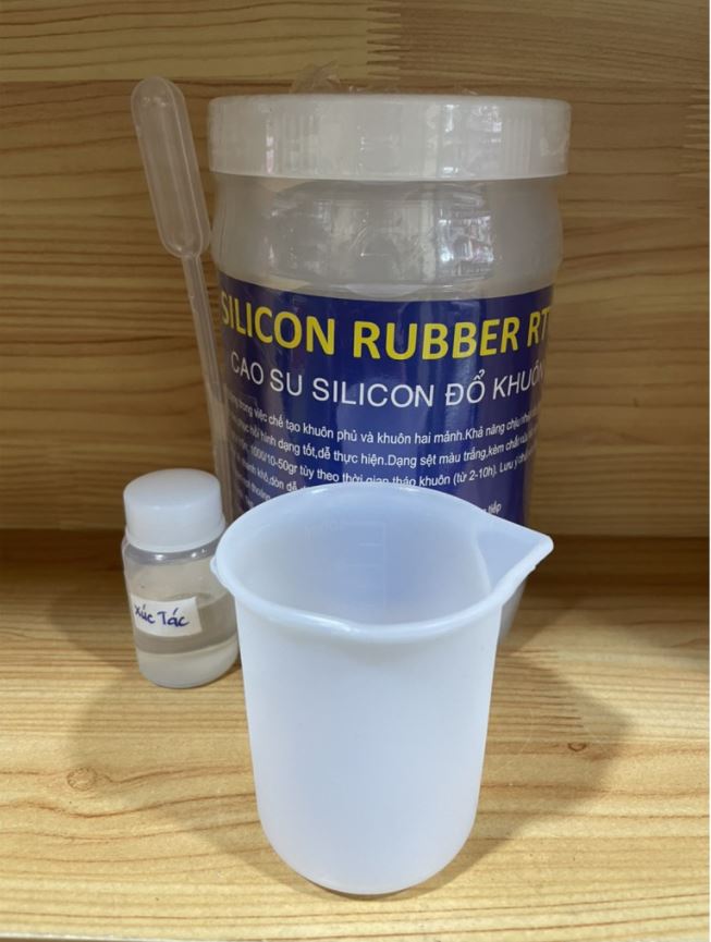

According to a seller’s description this RTV-828 silicon is suitable for making pacifiers and food molds.
Another casting material that I will test is Amazing Clear Cast Epoxy which I had obtained years ago for casting Google cardboard lens when it first came out.
As for the modeling wax, there was no retailer of File-A-Wax in Vietnam. Fortunately, I was able to purchase a couple of blocks from an artist who had originally bought them overseas for making jewellery.
Amazing Clear Cast Epoxy
Here are some key highlights from the MSDS - Use in a well-ventilated area - Wear gloves (butile or nitrite rubber) - Wear goggles - Avoid contact with skin and eyes. If skin contact occurs, remove with waterless hand cleaner or alcohol, and then soap and water. I - In case of eye contact, flush with water for 15 minutes and call a physician. In liquid form, this product is not to be used where food or body contact may occur.
The two resins A and B are to be mixed in 1:1 ratio by volume.
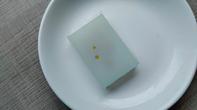
The manufacturer said its shelf life is 1 year. By now, I have kept them for 6 years. Their colours are a bit off, especially resin B which had turned brown. This is despite their original manufacturer’s seal. I mixed them up anyway and poured into a silicone mould sprinkled with a special ingredient - egg shell. Both the silicone mould and egg shell were meant for biomaterial experiments.
![]()
![]()
Their specs says:
- Open Time at 75 Degrees F (100 g mass) 30-40 minutes
- Demold Time at 75 Degrees F (100 g mass) 24-48 hours
- Full Cure Schedule 72 hours
Having poured the mixture into the moulds, it took me quite some time to gently pop or scooped away many of the bubbles. It was imposssible to remove all of them, only enough to make the pieces pretty much clear.
About 4 hours after being cast, the resin was already dry to the touch, but still flexible.
![]()
After 12 hours, I decided to demould it. It is quite dry, and flexible and came off the mould easily. I am quite happy with the result.
![]()
While cleaning up after casting, I did not pay attention and started washing off the resin residue on my hands with water which made them all sticky. I should have known better. Hand-washing soap failed me. I then used hand-cleaning alcohol but that did not work either. My hands were still sticky. I saw a tip from someone on the internet who said rubbing hands with coffee ground before washing with soap did it for him. I tried that too and it amazingly worked.
RTV-828 Silicone
- The seller was not able give me a datasheet for this material. However, from my research, it is an equivalent of Bluesil RTV-3428A silicone whose datasheet is provided in a link below.
- MSDS
- Technical datasheet
Here are some key highlights from the MSDS - Combustible hazard - In the event of contact with the eyes, rinse thoroughly with clean water. Continue to rinse for at least 15 minutes. - Use mechanical ventilation in case of handling which causes formation of vapors. Do not mix with Incompatible materials. - Storage instructions: Store in a cool, dry place with adequate ventilation. Keep away from incompatible materials, open flames, and high temperatures. Store in tightly closed original container. Suitable containers: polyethylene. Steel drums coated with epoxy-resin. During storage, this product may generate hydrogen gas. - Recommended PPEs: Safety glasses, and protective gloves made of: Nitrile. Polyvinyl chloride (PVC). Rubber or plastic.
Ferris File-A-Wax, Green colour
Here are some key highlights from the MSDS - Not a hazardous substance - Provide exhaust ventilation or other engineering controls to keep the airborne concentrations of mists and/or vapors below the recommended exposure limits (see below). An eye wash station and safety shower should be located near the workstation. - Use normal precautions when handling hot molten liquid solutions. Do not breathe fumes or vapor from heated material. Do not allow hot material to contact skin. Provide appropriate exhaust ventilation at places where dust is formed. Try to avoid creating dust. - Storage instructions: Store at ambient temperatures in closed containers. Avoid heat and open flames, as this material can catch fire if overheated. - Recommended PPEs: use safety glasses equipped with side shields, and disposable nitrile, neoprene or butyl rubber gloves with repeated or prolonged use. - Thermal oxidative decomposition can produce CO and CO2.
Individual assignment
Research
How to Create a Two-Part Mold in Fusion 360
Casting polyurethane resin into alginate
FabLab Kamakura’s Mold Making Tutorial in Fusion360
DIY Machinining Wax
To my dismay, I could not find a supplier of File-A-Wax in my country.
Recipe 1
Source: Leeds Hackspace
4 parts paraffin wax to 1 part plastic (LDPE)
This recipe originally came from Instructables.
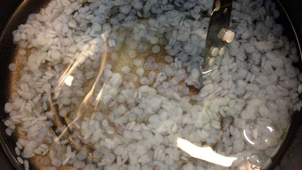 Image source: Leeds Hackspace
The resulting blocks look so nice that I wanted to try making it myself.
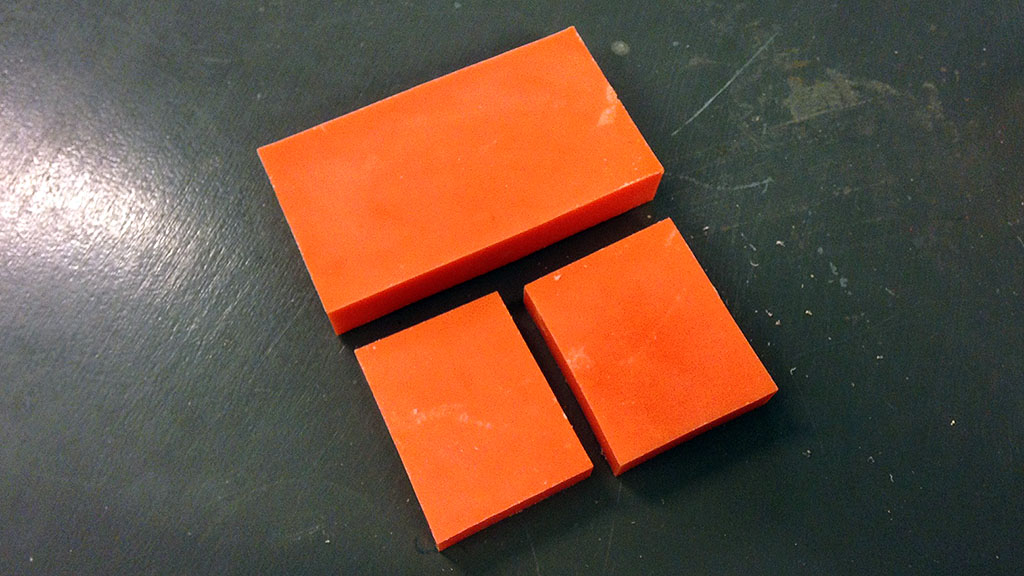 Image source: Leeds Hackspace
Recipe 2
Source: CNC Zone
Mix 7.5 parts paraffin candle wax with 1 part Polyethylene sheet For a bit harder wax try 8-8.5 parts wax with 1 part Polyethylene sheet
For a more flexible wax try 6-6.5 parts wax with 1 part Polyethylene sheet
For a durable wax that has less of a waxy feel, try 6.5 parts wax, 1 part polyetheylene sheet and 0.5-1 part low temp hot glue sticks (A.C. Moore Craft store brand melts at 230 degrees F and easily dissolves) the downside of this wax is it doesn’t hold an edge quite as well but would be great as a prototyping wax as its reusable and flexible to a degree. However I wouldn’t recommend burning this wax as a cande.
For even more flexibility (but less tensile strength) try the following: 7 parts wax, 1.5 part hot glue, 0 parts plastic. It produces a rather unique plastic thats extremely flexible.
Designing an object to be molded
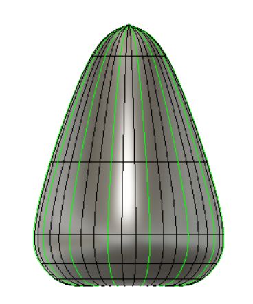
For this exercise, I want to make a model of a cashew fruit but not necessarily a realistic one.

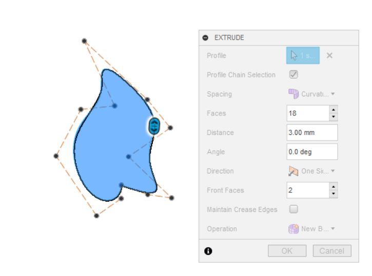
I created a sketch in Fusion 360 using T-spline.

Next, I selected Create form and moved to Sculpt mode. In the scroll-down menu under Create, I clicked Revolve.
The settings used in Revolve menu are - Spacing : curvature - Faces : 9 - Type : Full - Faces : 14 - Symmetry : Circular - Symmetry faces : 3 -
Edit form, and move the axis in by 1mm. This makes w12-f360-revolvedone-clearsymm.jpg
I thickened the shell to 3mm. Using the inspection function, you can see this
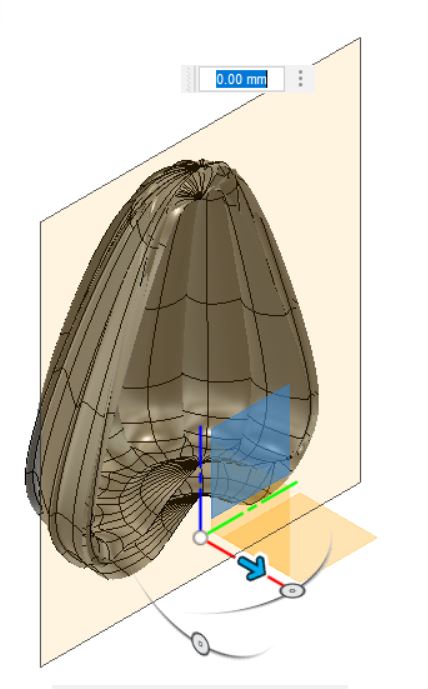
Unfortunately, I encountered an error when clicking on Finish form.

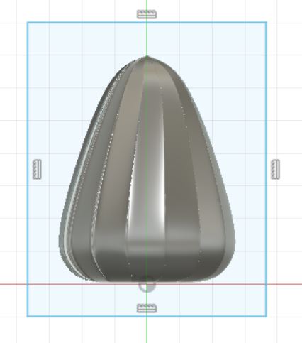
I decided to undo thickening and press on Finish Form. Fusion 360 allowed me to do so this time.
Designing molds
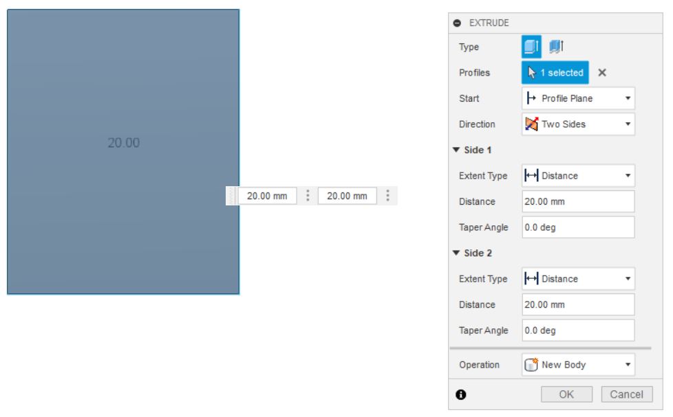
From here I would like to create a mold, so I sketched a rectangle and extruded it to both sides by 20mm to make a new body.
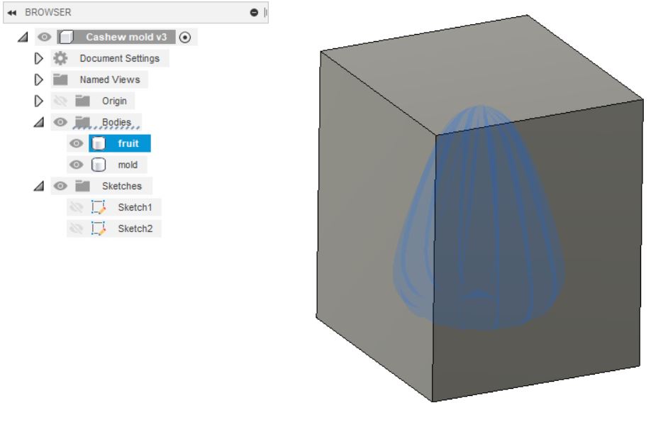
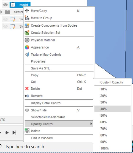
I renamed the bodies to ‘Fruit’ and’ Mold’, before clicking on Mold > Opacity Control > 40%
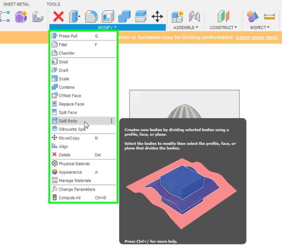
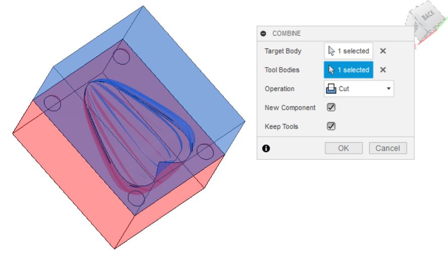
The next step is to subtract the object from the mold. Click Create and select Combine under the dropdown menu.
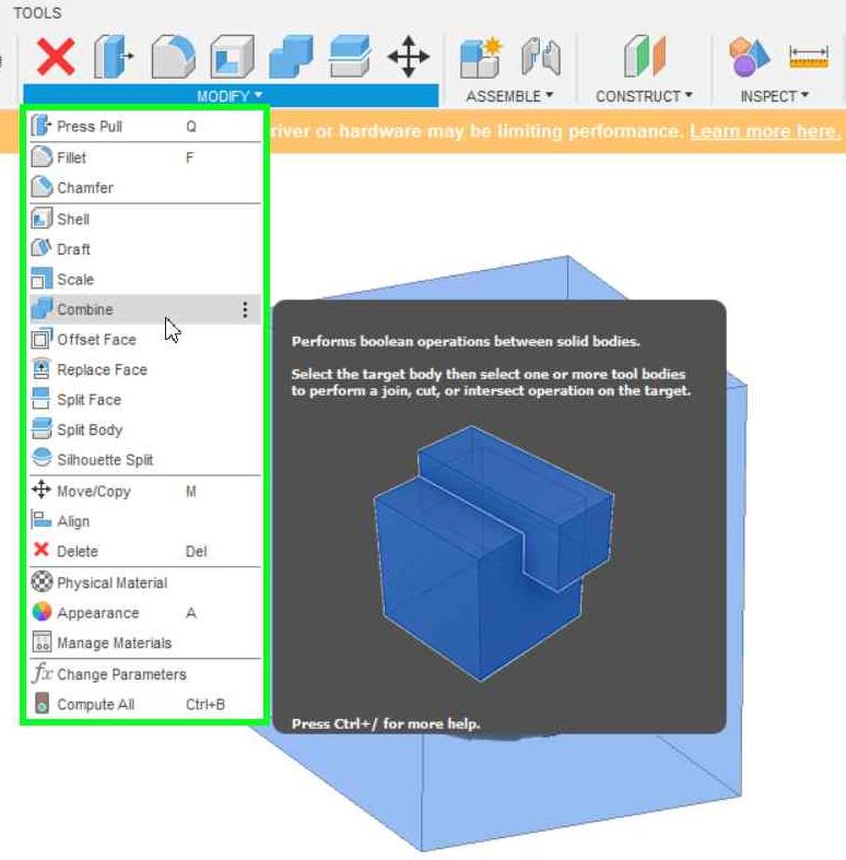
I selected Mold in ‘Target body’ and Fruit in ‘Tool bodies’, as well as Cut in Operation. ‘New body’ and ‘Keep tools’ are checked as well.

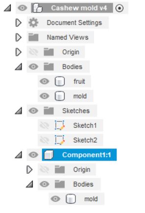
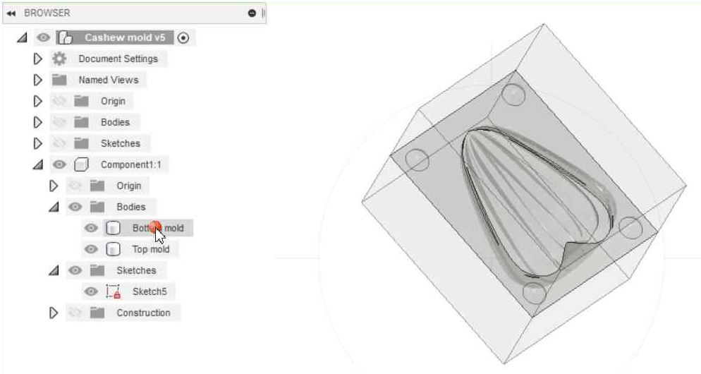
A new component has been created, namely Component 1. I switched off the original Fruit and Mold bodies to keep things simple.
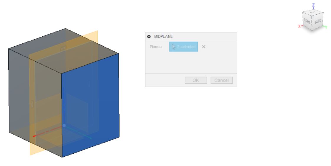
Next we want to split the mold into 2 parts. Before I could do so, I constructed a midplane to specify where the Fruit Mold body should be split apart.
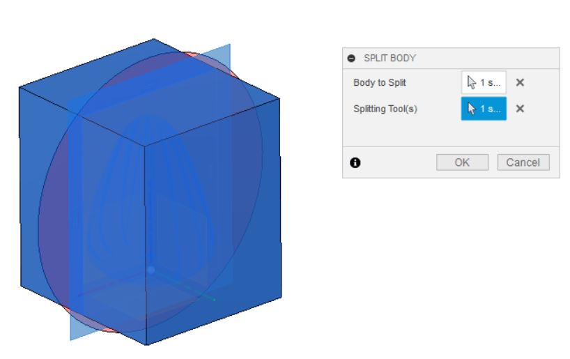
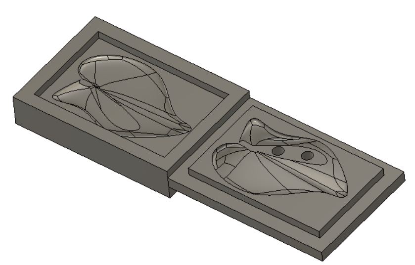
Once the split operation succeeded, Component 1 will have 2 new bodies. I renamed them as Top Mold and Bottom Mold.
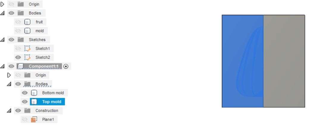
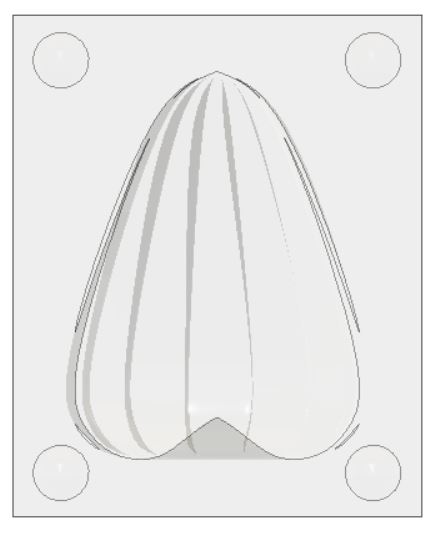
To see what the inside of the mold is like, I hide one of the two molds, which in this case is the bottom.
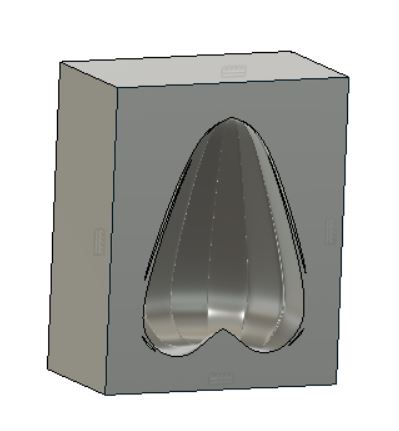
At this point, I realized that there are a couple of issues with the model, the biggest one being that the bottom of the fruit made it impossible for an endmill to get in. Even if I split the fruit horizontally instead of lengthwise, I will still run into the same issue of the endmill not being to get to certain parts.
Making registration marks
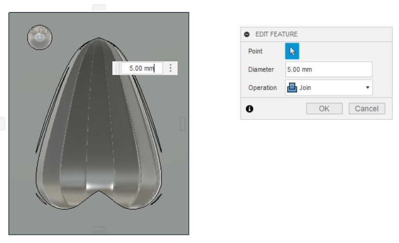
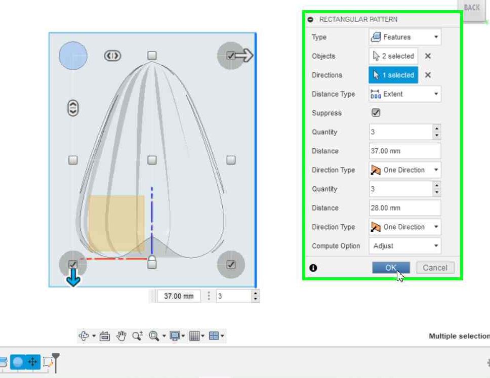
Using Sphere feature from the Create drop-down menu, I created a hemispherical registration mark with a 4mm diameter on the top mold.
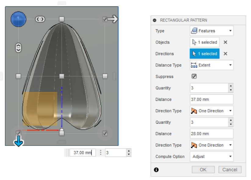
Using pattern feature, I then replicated the marks at the other corners
Now we should subtract these features from the top mold. Using Combine function once again, select the bottom mold as ‘Target body’ and top mold as ‘Tool body’.
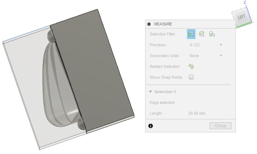
Using measurement tool, I saw that the mold is thicker than necessary and would like to reduce the thickness to save material. For that, I went back the Extrude step and clicked Edit extrude before reducing the distance from 20mm to 16mm.
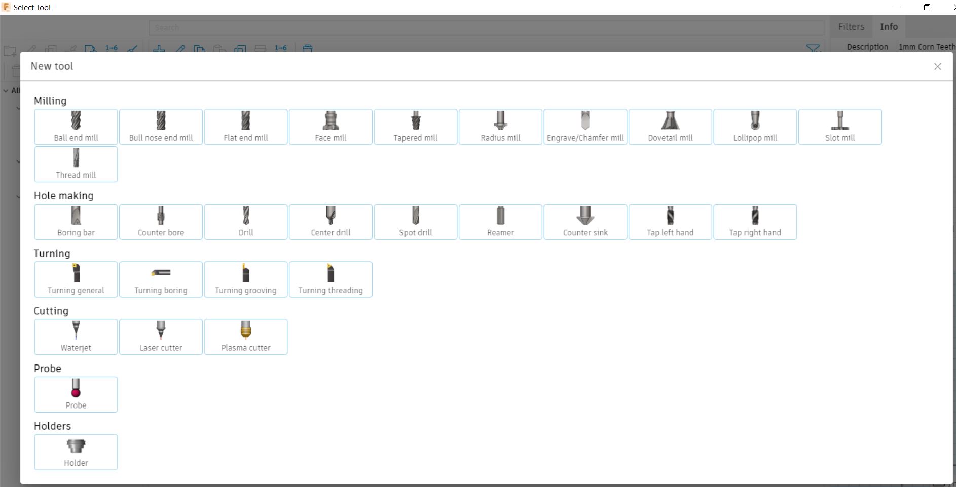
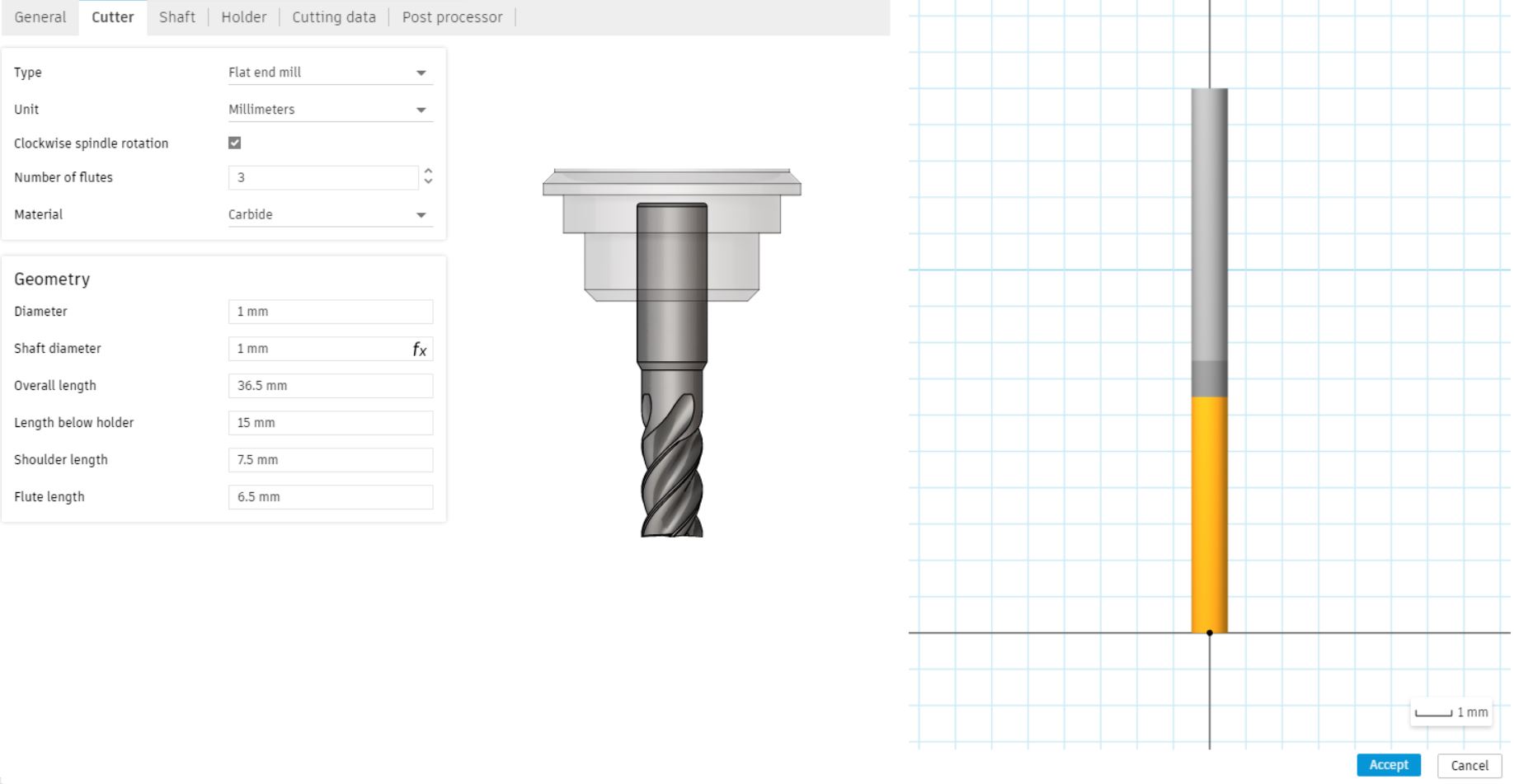
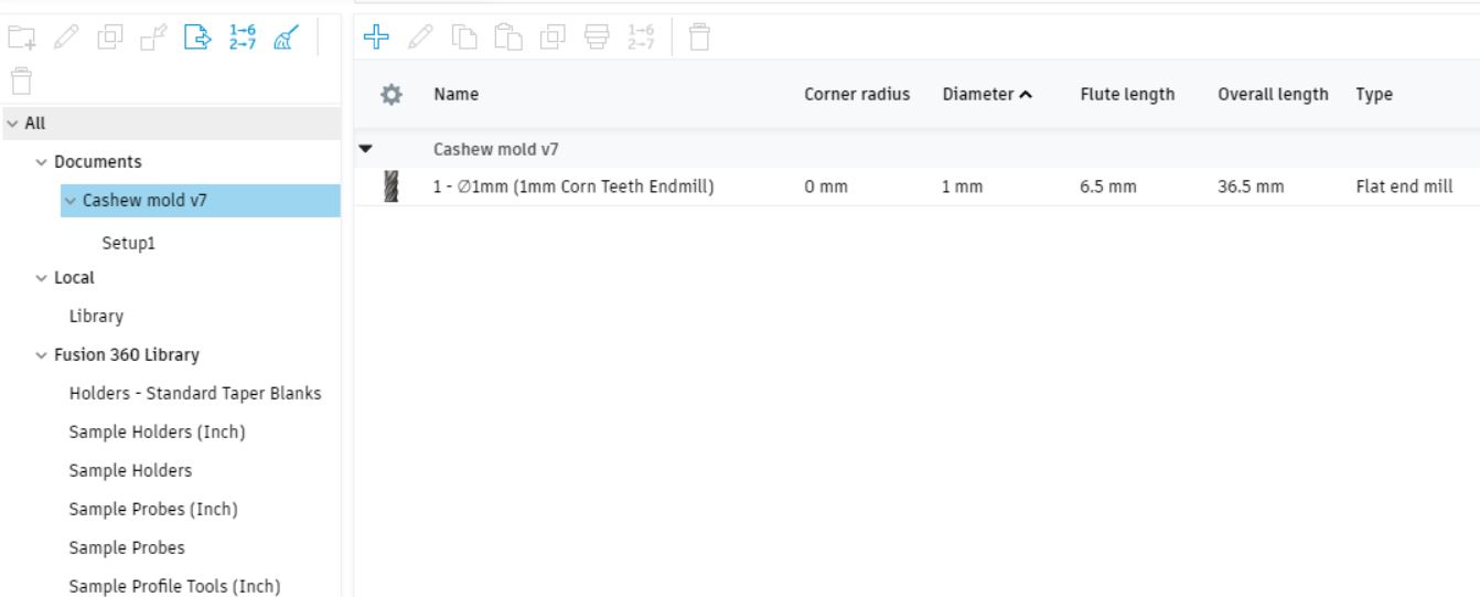
Milling in Fusion360
![]()
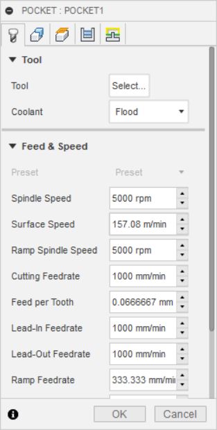
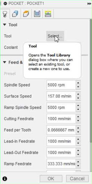
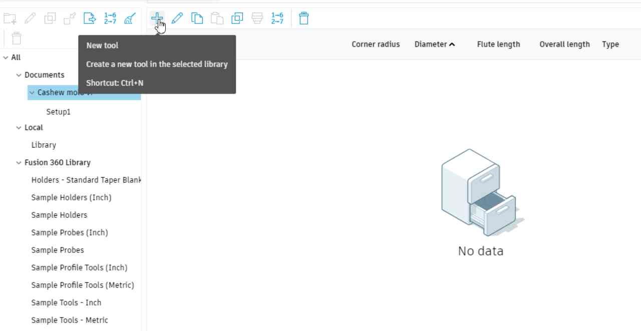
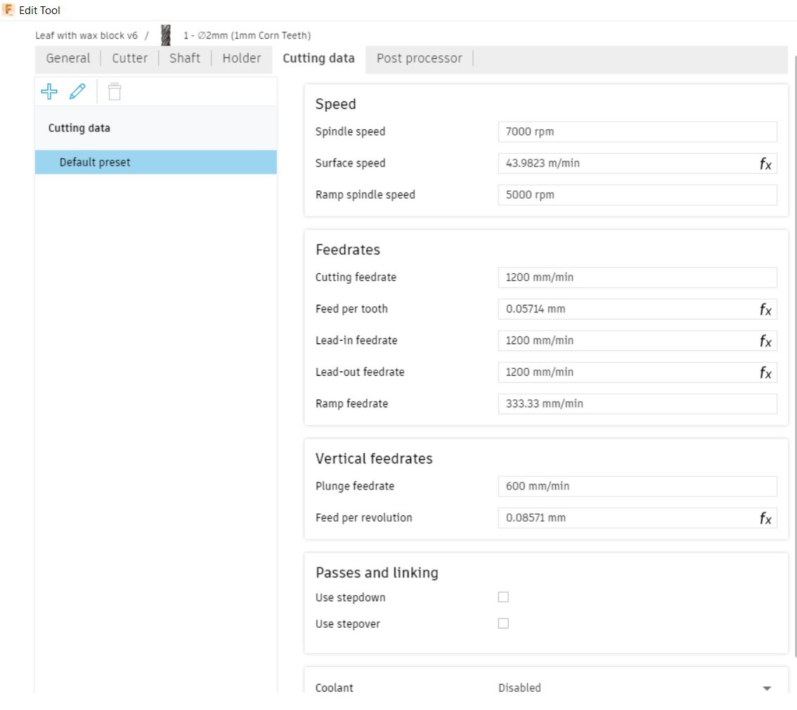
I defined the cutter that I would be using. It is a 1mm corn teeth endmill.
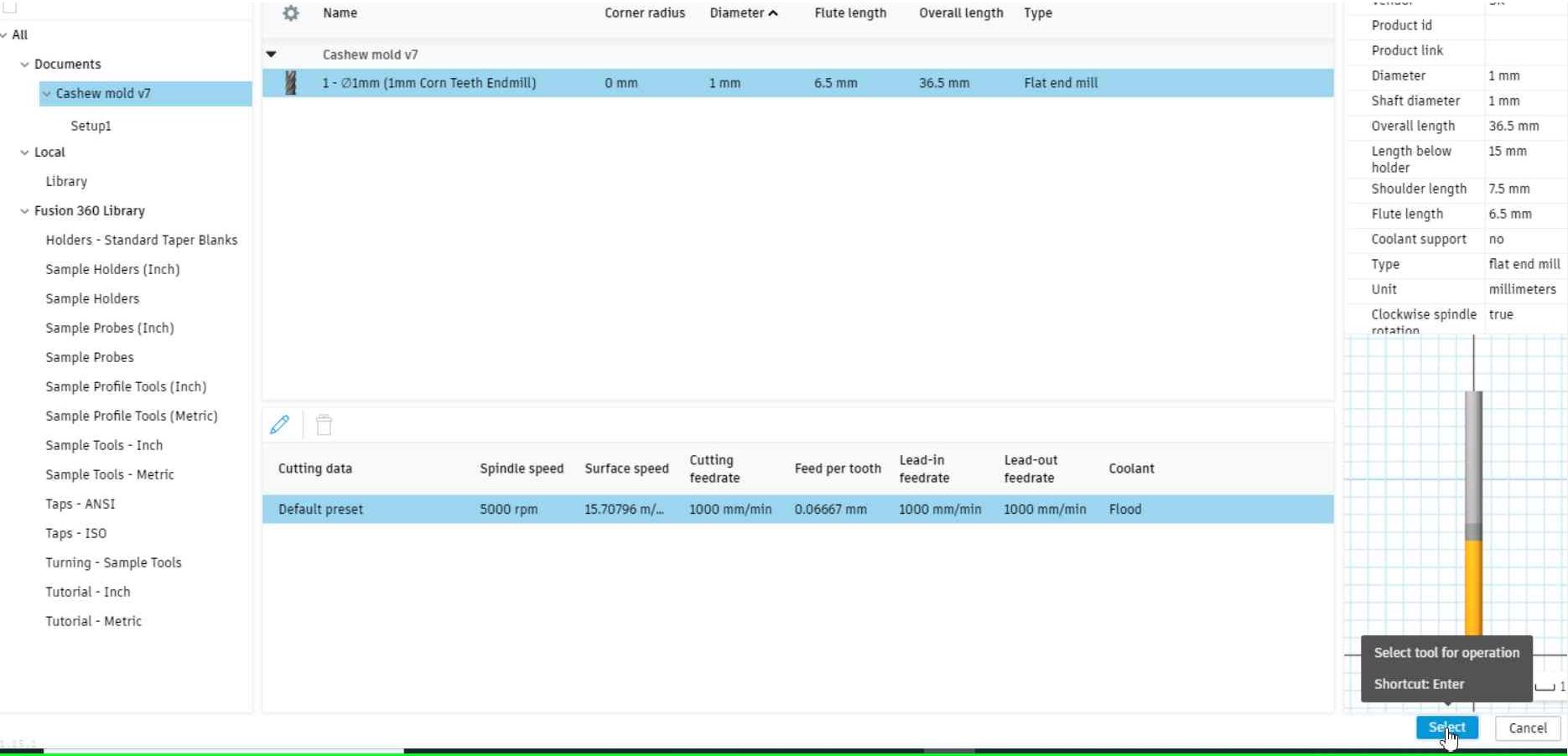

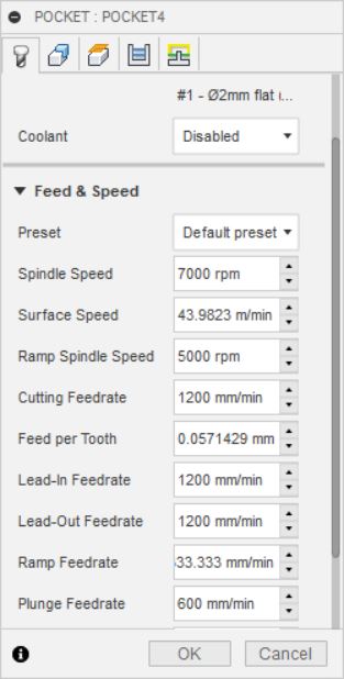
Once the tool parameters were set, we could go back and select it in the Pocket dialogue.
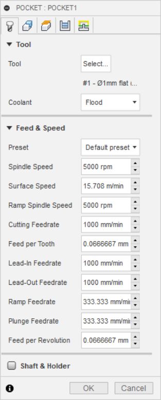
I changed the cooling option from Flood to Disabled and reduce the feed rate to 500mm/min.
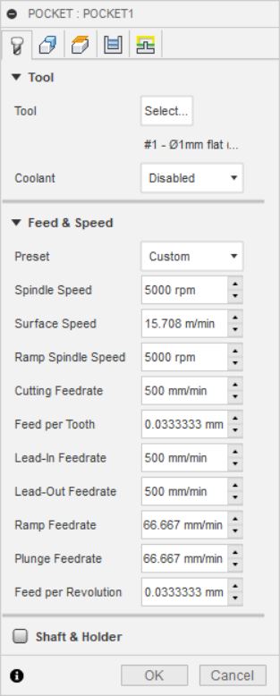
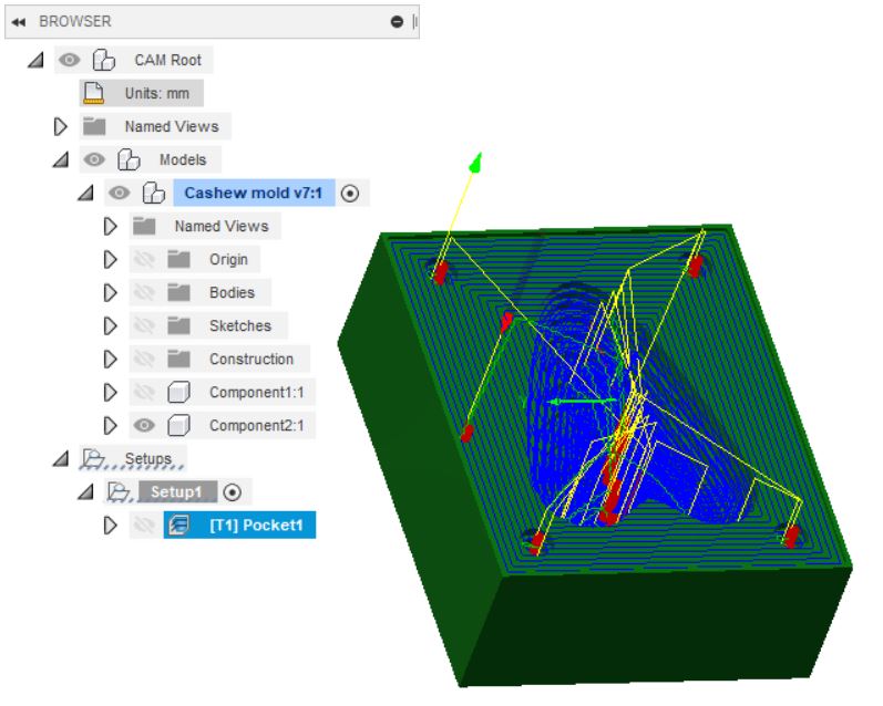
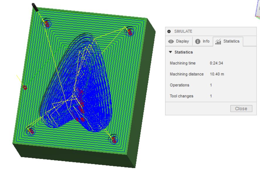
Once I clicked OK, the toolpath immediately became visible.
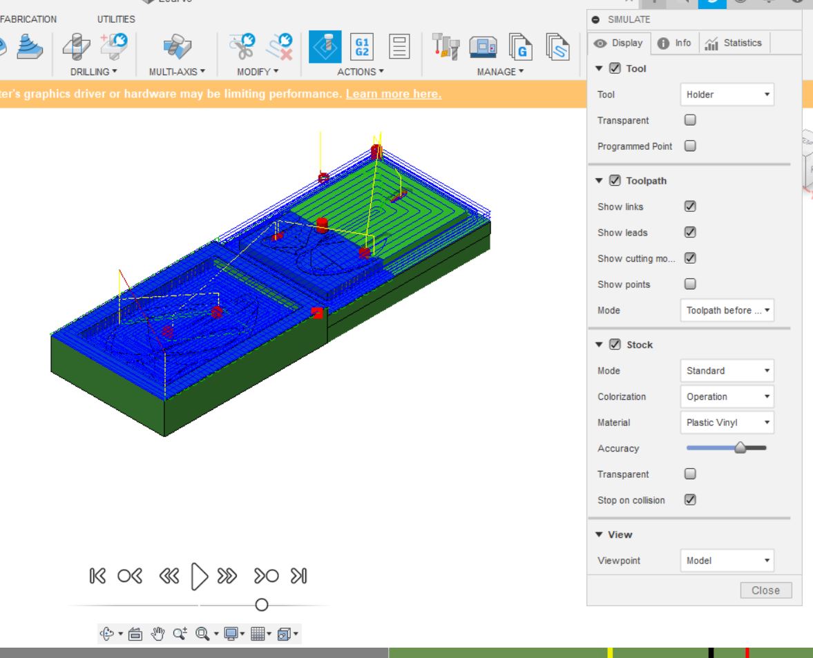
To simulate the tool path, I clicked Simulate. A dialogue popped up and I clicked Play button.
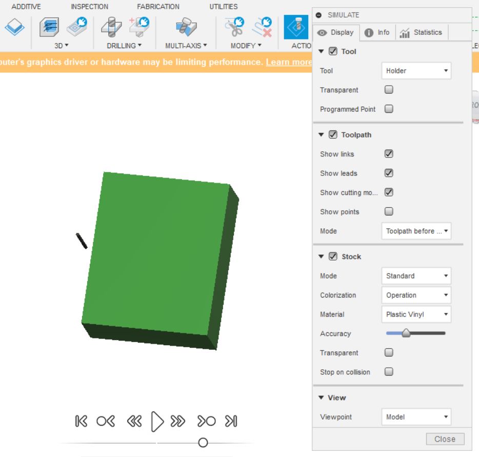
The Statistics tab provides a handy estimate of the milling duration.
To export the toolpath, I clicked on Actions drop-down menu and selected Post process.
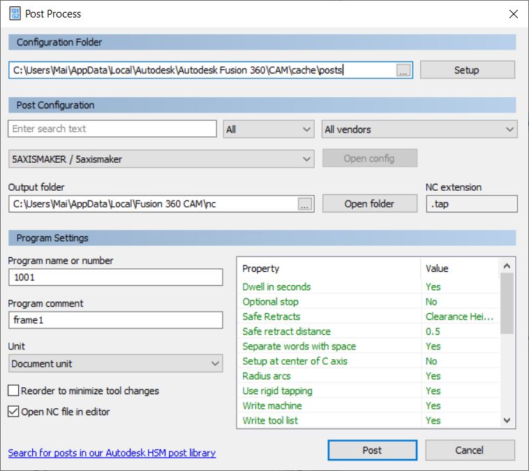
Having selected GRBL in the Post Configuration, I clicked OK.
Fusion360 then asked to Download Visual Studio Code for viewing post processed results but I clicked Cancel, thinking I don’t need that yet.
Immediately, a text file appeared, stating Error: Milling toolpath is not supported by the post configuration.
Failed while processing onOpen().
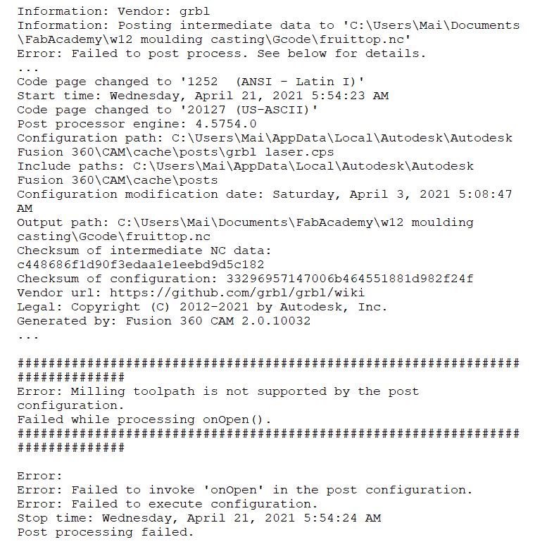
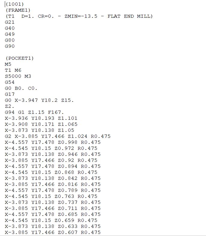
I went back to Post process step, this time selecting 5axismaker in the vendor list. The .tap file is successfully processed. This confirms that we need a 5-axis machine to do this job.
Modeling a leaf
Following a similar procedure to the previous step, I decided to design something flatter for easier milling.
I started with a sketch, and created form before extruding it.
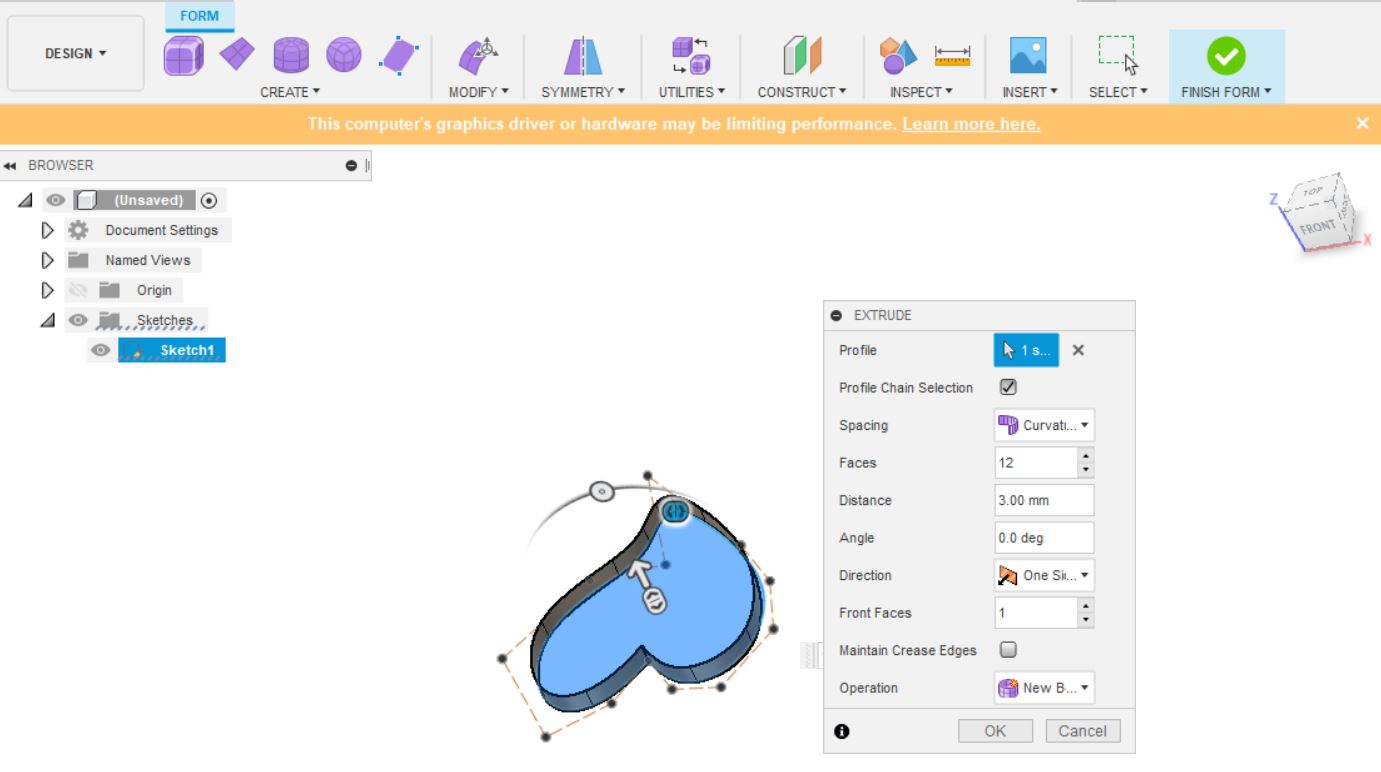
This time I made a complete wall for registration.
My molds are ready for processing by a CAM software .
Processing in a CAM software
Moving on to Fusion360 Manufacture workspace, I generated 2 milling operations: a pocket and a parralel one, the former for roughing purpose and the latter for finishing.
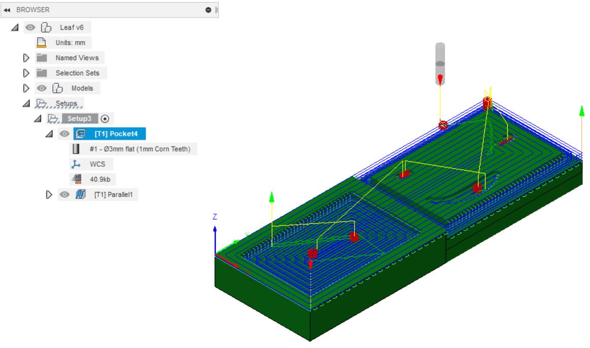 Pocket toolpath
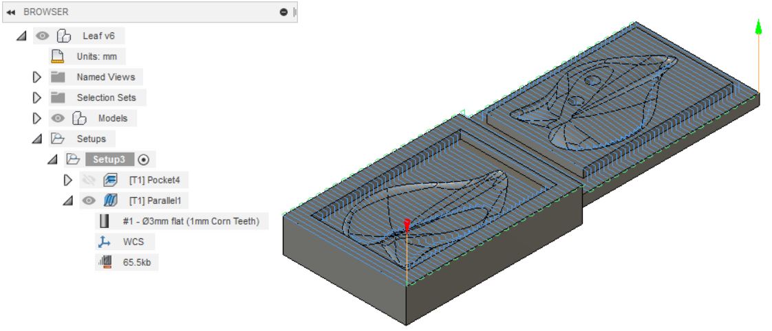 Parallel toolpath
Subsequently, the toolpaths are post-processed to a grbl format that can later be imported to our Mach3-controlled CNC machine in the lab.
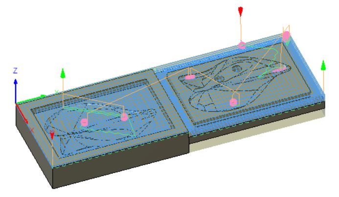
Fusion 360 has a handy feature simulating the toolpaths.
[Note to self: include recorded simulation]
Issues encountered
-
While setting up the stock in Fusion360 Manufacture, my stock is twice as big as what it should be. I made sure there was zero offsets in any direction on top of relative stock size. It took me 2 hours to figure out that it is because I had selected the whole Leaf model which has parts that are not meant to be milled. Eventually, I found out that I could select only the top and bottom mold bodies, and that’s when the stock wrapped tightly around the molds as it should be.
-
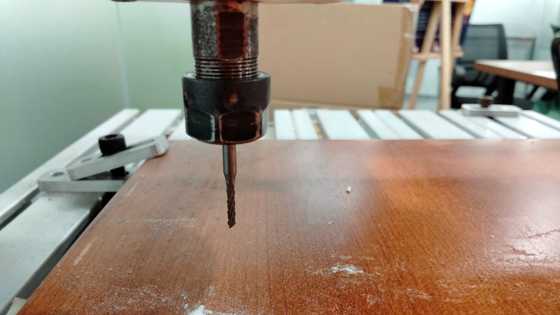
When I started this job in my machine, the spindle always tried to plunge deep below zero point - where the top surface of the block lies. It is such a puzzling move.
-
Collision between shaft and stock
Since I checked the ‘Stop on collision’, the simulation stopped where a collision was detected. The cause was ‘shaft collides with stock’.
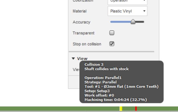
My first hunch is that the end mill that was configured in ‘Tool’ might be too short. True to my suspicion, the depth of the hole is 8mm, whereas the length below shoulder was 7.5mm. The difference is very little so I just changed the length below shoulder to 8mm. The software was happy and able to simulate the whole sequence without stopping.
- Finally, I realized that I had been milling the wrong thing. There is still a step missing after the molds have been created, which is making a mold of the mold. As a result, I went back to the modeling stage.
Making a mold of the mold
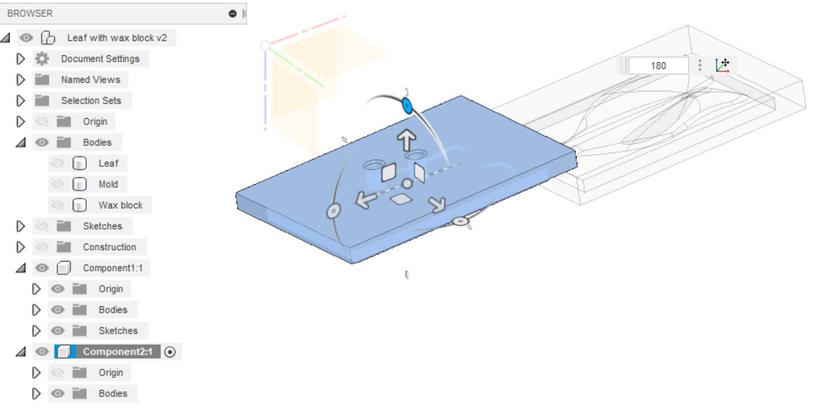
In Fusion360, I extruded the thinner mold of the two created earlier so that they have equal thickness.
Modeling: When the position is satisfactory, run the ‘Combine/Cut’ command similar to Step 3…choosing the ‘Wax Block’ as the ‘Target Body’ and the 2 ‘Soft Molds’ as the ‘Tool Bodies’, making sure again that the ‘Keep Tools’ checkbox is checked.

Next, I flipped them in the z direction. Now both molds were facing down.
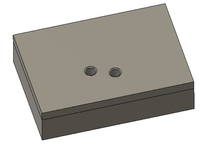
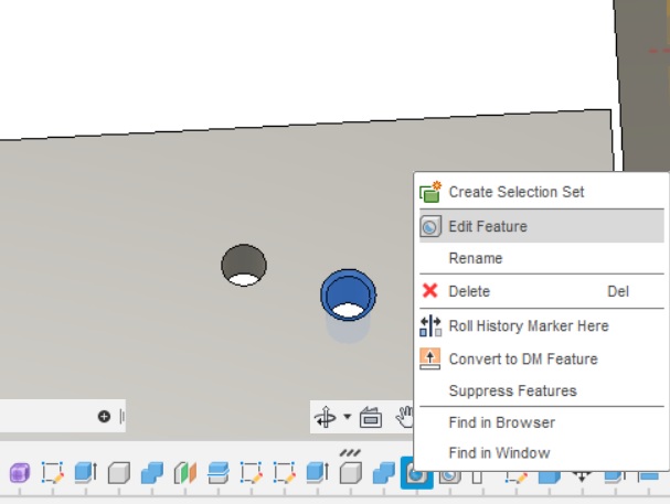
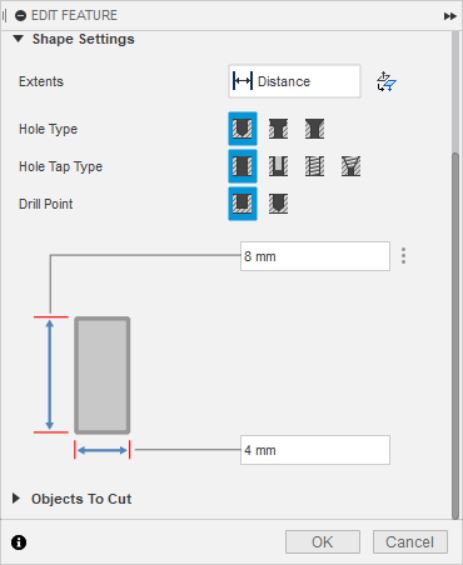
Having done that, I realized that the countersunk holes specified earlier on cannot be milled in this orientation, so I edited them to make a simple, straight-type hole.
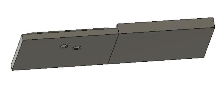
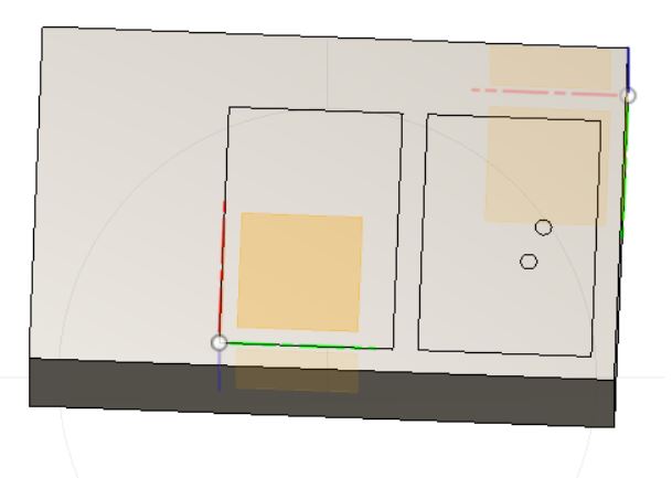
Using Move and Align commands, I positioned the molds inside the wax block such that their top surfaces are flushed and the molds are 6mm from the edge of the wax block.
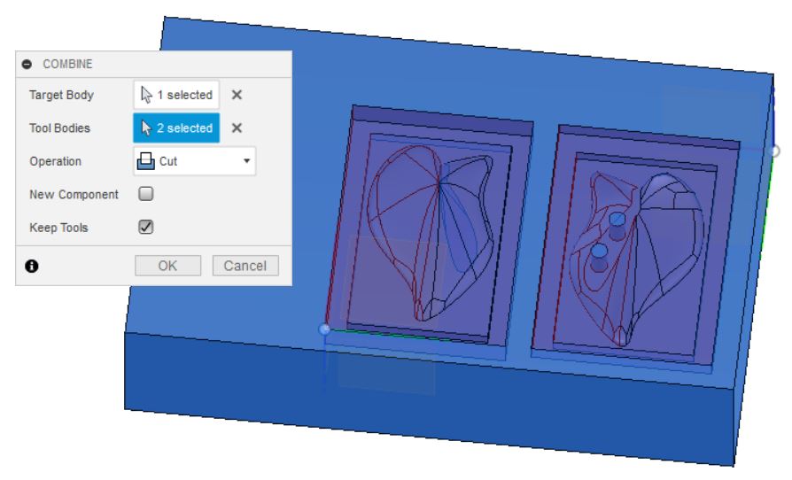
When the position was satisfactory, I ran the ‘Combine/Cut’ command selecting the Wax block as the ‘Target Body’ and the two molds as the ‘Tool Bodies’. I also checked ‘Keep Tools’.
The result is finally suitable for milling.

Milling
Without access to File-a-wax, I plan to mill the mold out of wood and floral foam. I will update when I have the results, sometimes before 25 April.
To my luck, a local jewellery artist wanted to sell his casting materials before moving out of Vietnam. I bought two File-a-wax blocks from him. They are green in colour, meaning that they are the hardest type manufactured by File-a-wax, and come in 93mm x 142mm x 36mm size.
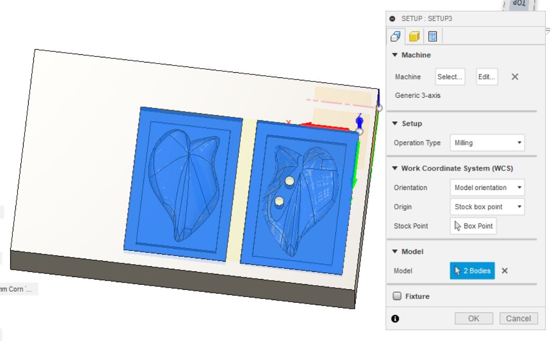
Moving to Manufacte workspace, I edited the setup created earlier, re-selected the two molds in ‘Model’ and specified a new model origin.
Create a setup, select model origin and select Bodies.
This time round, I planned to use a 2mm corn-end bit to speed up the miling process, hence updating the tool parameters.

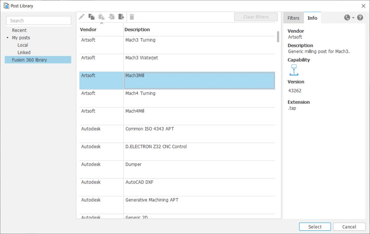
Having updated the tool, I chose Mach3Mill as the post-processor.
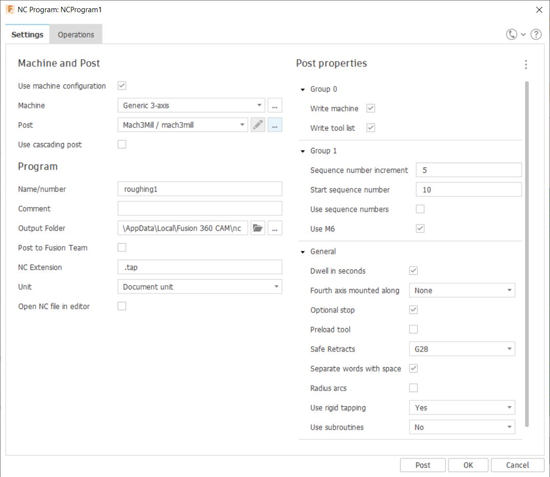
I proceeded to load the gcode file in Mach3 - the CNC machine’s software. In the path preview panel, I noticed some odd momevements where the spindle would go quite deep down below the starting surface. Looking into the Gcode generated by Fusion 360, I found that the odd momevement is caused by this line in the code - G59 P50.
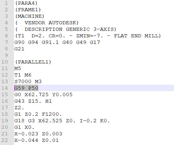
This means that the machine was using a coordinate system namely G59 instead of G54 - the active one.


I deleted the above line and the visualized path now made more sense.
Here is the result at the end of the roughing pass,
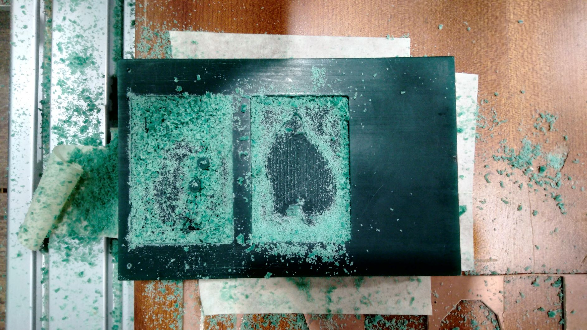
and at the end of the parallel pass.

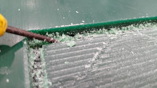
At this stage, the mold looked surprisingly quite rough so I ran a morphed spiral to make better finishing. It did improve things quite a bit, especially around the upper edges. This made me question whether I should be using a different bit to achieve a cleaner cut. Again, time was too short for another milling attempt so I picked up a small flat-headed screw driver, and started chiseling away the extra bits of wax that stuck to various surfaces.
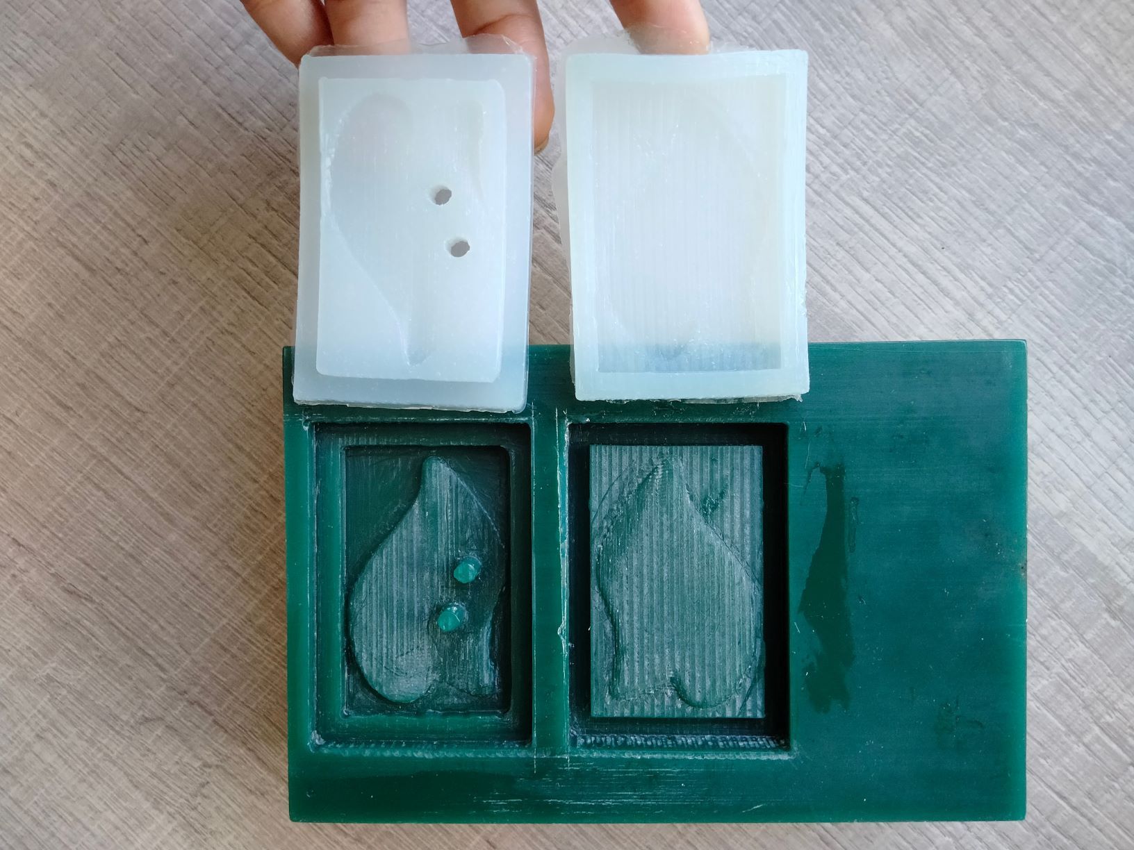
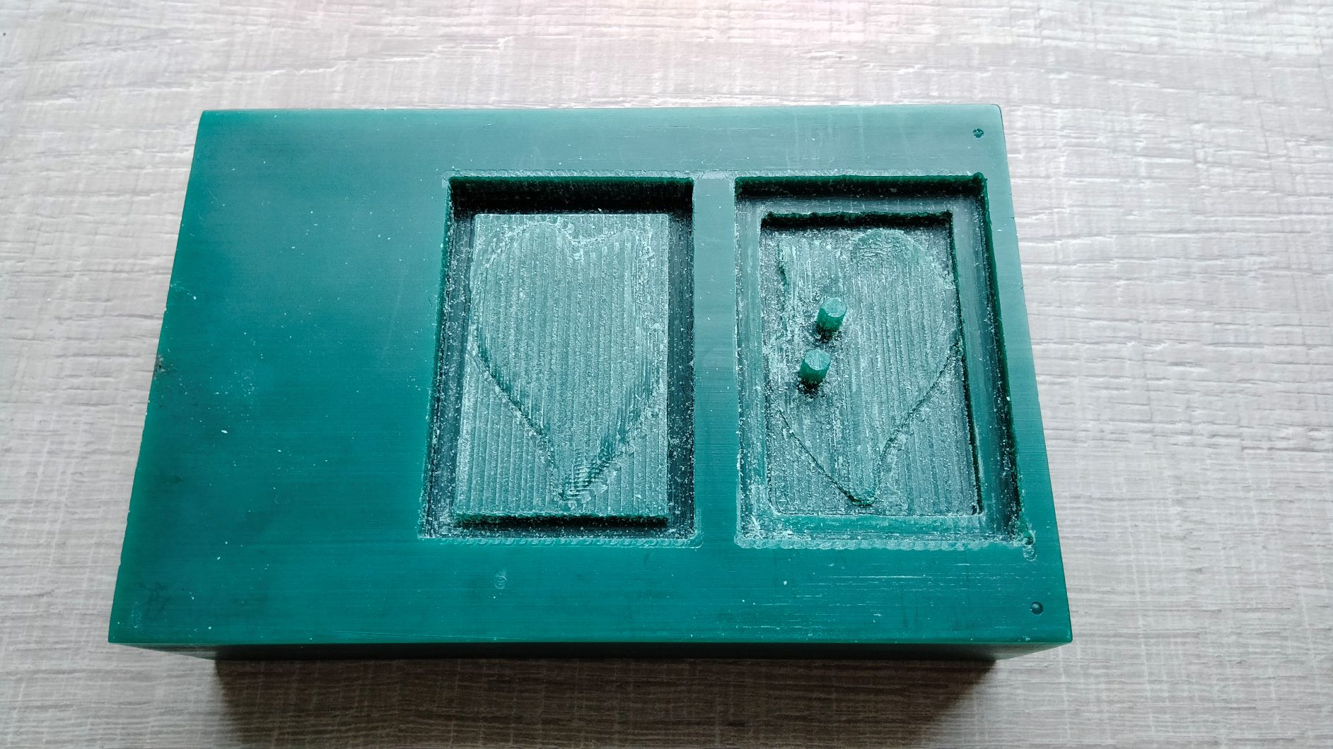
Finally I ended up with this mold.
Casting
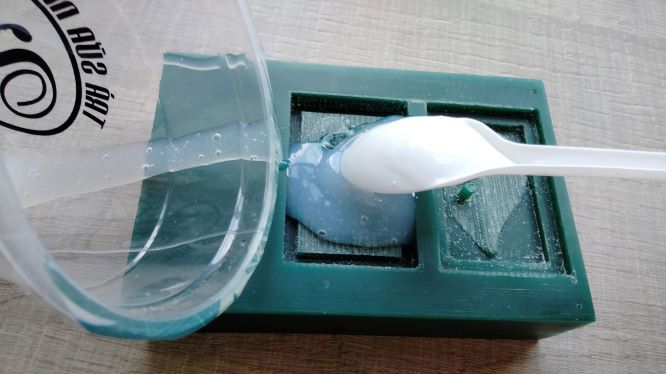
Now comes the exciting part of the assignment. I measured 40g of silicon and 0.4g of the setting catalyst (10:1 ratio) and used a spoon to mix well for about 30 seconds before pouring it to the mold. After about 3 minutes, the mixture became to thick to remove from the cup.
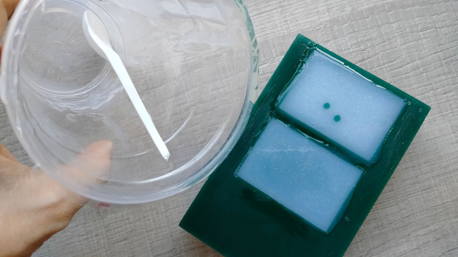
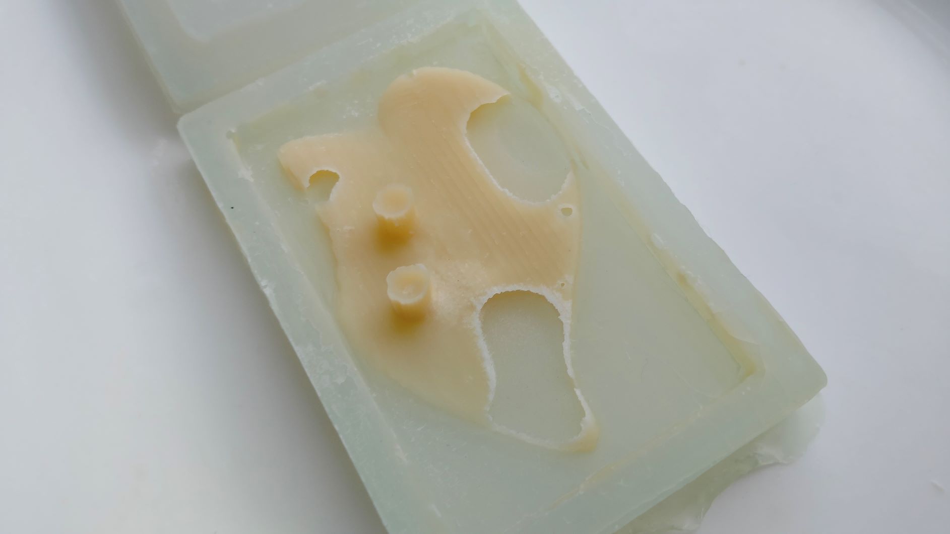
Sixteen hours later, I demolded the cast. It was softer than I had expected but it came off quite easily.
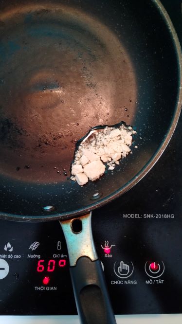
I melted some cacao butter in a frying pan on low heat before pouring it into a hole with a spoon.
With the cacao butter all in, I put the mold inside the fridge, holding my excitement.
Half an hour later, I demolded the butter and to my surprise, it was less than perfect, having suffered from 3 big bubbles.
Although I had fulfilled the assignment requirements, I would be thinking about how to tackle the bubble challenge in order to achieve a completely casted cocoa butter leaf.