Final Project
slide
video
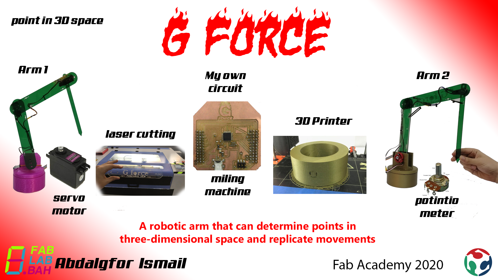
What does it do?
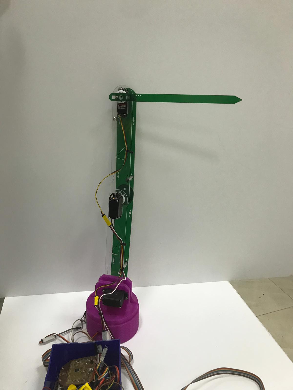
It is an robotic arm that can determine points in three-dimensional space in order to convert these points into a three-dimensional model I will have to take some measurments which will be automatically taken by my robotic arm this is can be done when I have potintiometers in my arm then using forward kinimatics calculation I can determine my 3d position the x position and y position and z position this can be possible if I used four potitiometers.
2D and 3D design
I designed the arms using Fusion360 “2D” and two bases for them

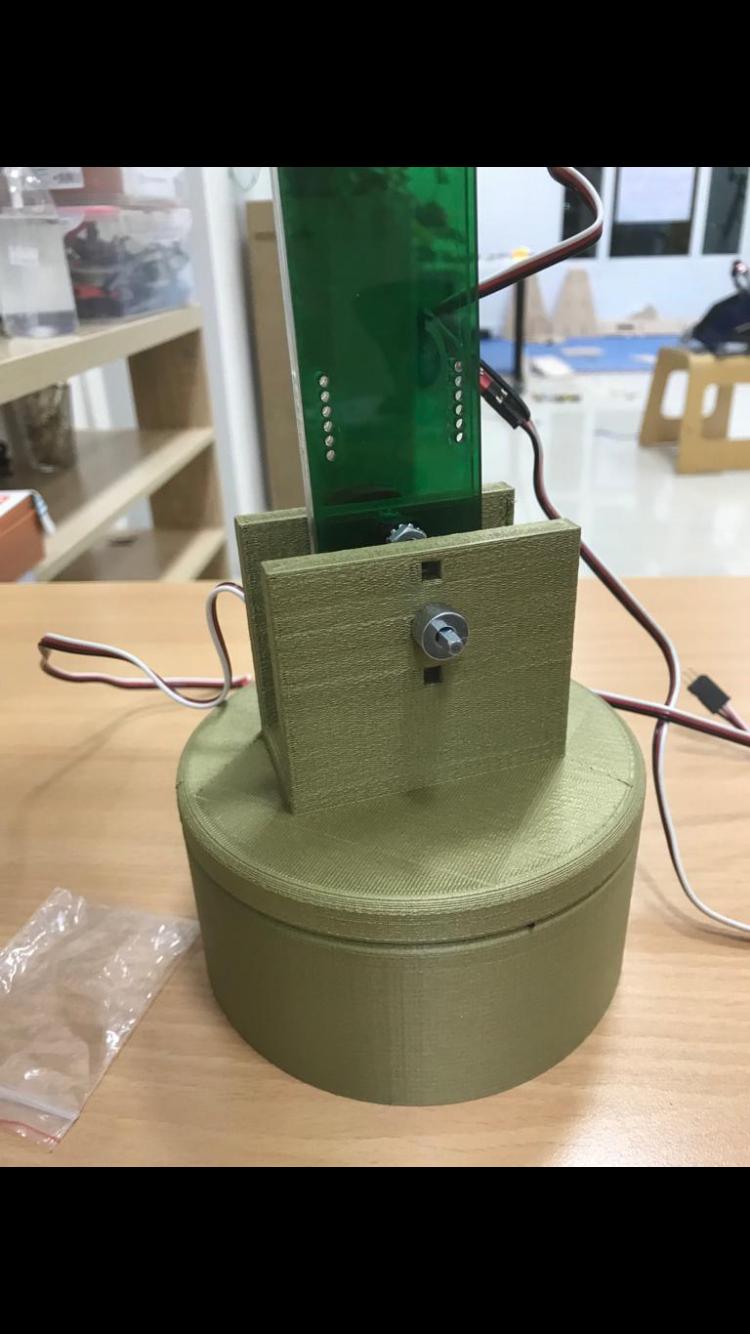
3D printing
I 3d printed my 3D designs which was the two arm bases
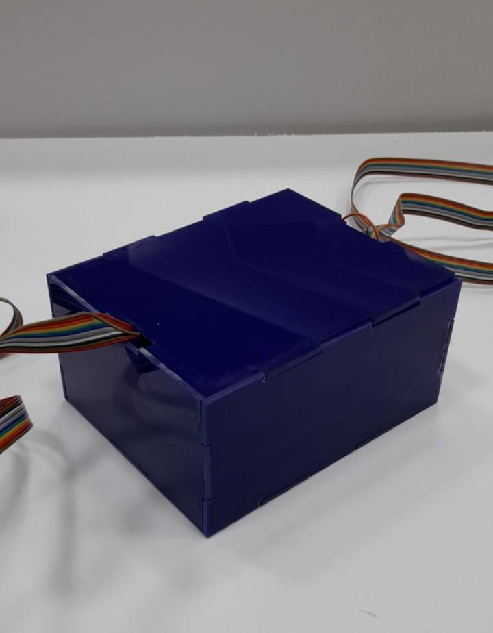
Laser cutting
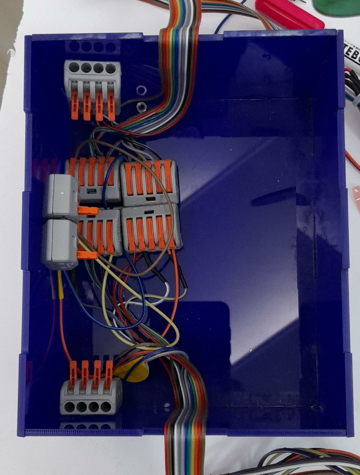
I laser cut my two arms structure and a connection box to hide all my wiring

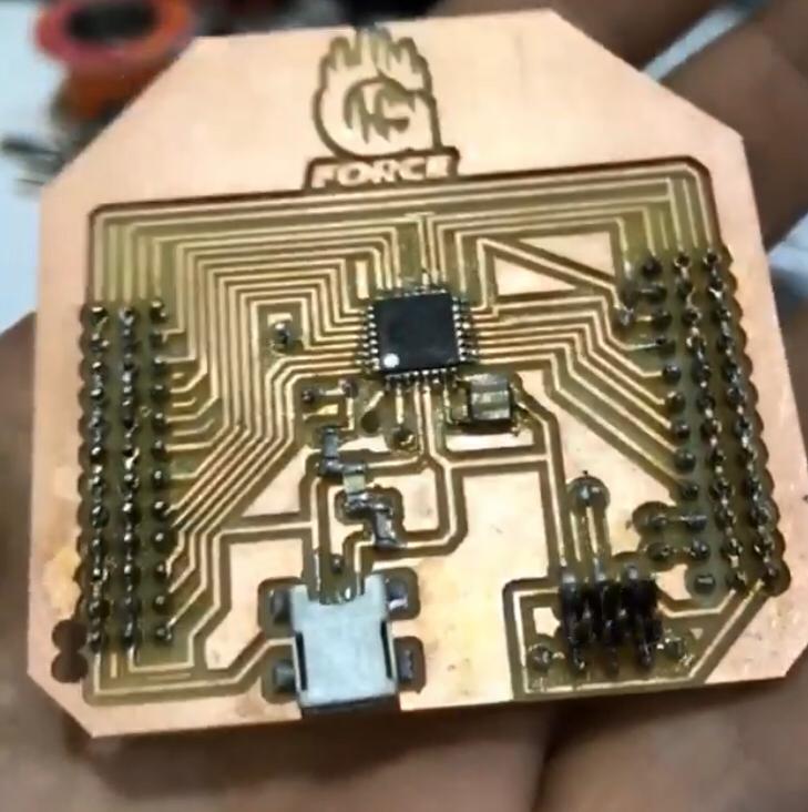
Electronics
I used the circuit which I designed and milled in week 7 and connected it with Inputs which were the potintiometers in the input arm and Outputs which were the servo motors in the moving output arm
Input arm
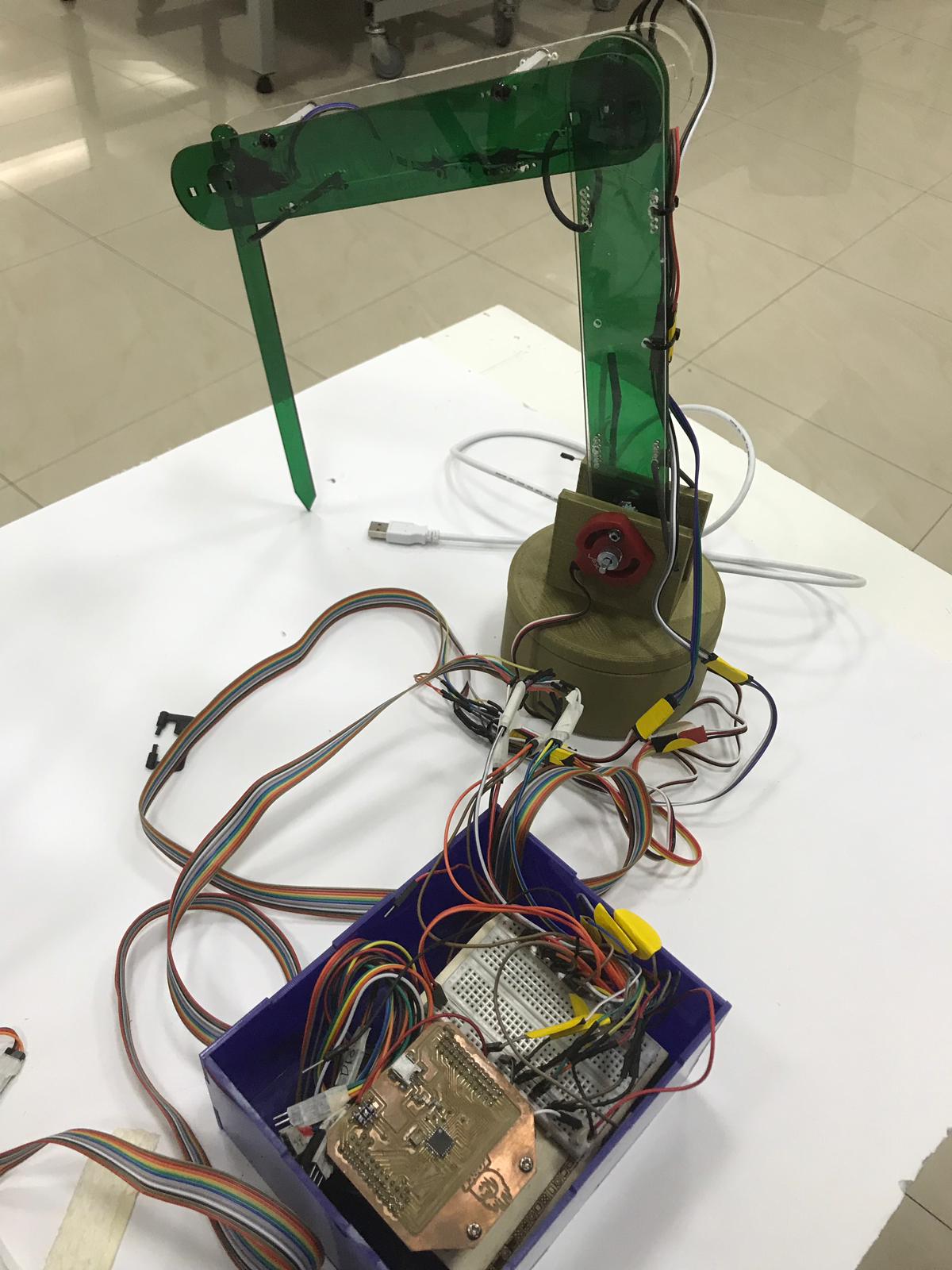
Output arm
common VCC ,GNG
I improved my wirring using these termenal blocks it worked good my project wirring is now more clean
Interface
I used grasshopper to interface and do the calculation I needed to process the data from the potintiometers to the servo motors
How much did they cost ,where they will come from ,components used
| Qty | Description | Price | Link | Notes |
|---|---|---|---|---|
| 4 | variable resistance | 8.000 BD | https://www.instagram.com/elec360.bh/ | |
| 1 | Wires | 2.000 BD | https://www.instagram.com/elec360.bh/ | |
| 1 | Microcontroller | 6.000BD | https://www.instagram.com/elec360.bh/ | |
| 1 | Acyrilc sheet(thickness:10mm) 30x60 cm | 7.000BD | https://www.instagram.com/elec360.bh/ | |
| 1 | power supply | 5.000BD | https://www.instagram.com/elec360.bh/ | |
| 1 | Screws | 4.000BD | https://www.instagram.com/elec360.bh/ | |
| 4 | Servo motor | 14.000BD | https://www.instagram.com/elec360.bh/ | |
| 1 | Pla filmant | 5.000BD | https://www.instagram.com/elec360.bh/ | |
| 2 | Swich | 3.000BD | https://www.instagram.com/elec360.bh/ |
what will happen when? “Time and work managment”
| Name | Description | Time needed |
|---|---|---|
| 6. 3D Scanning and printing | I 3D printed the base of the final project and some potentiometer attachments | 1 weeks |
| 7. Electronics design | I will build my circuit that will do the processing and ingrate it with output and input weeks | 3 weeks |
| 10. Input Devices | Integrate my input which is the 4 potentiometers | 2 weeks |
| 12. Output Devices | Integrate my outputs which are the servo motors | 2 weeks |
| 13. Interface and application | programming I will do a interface so I can do my calculations and display After that I will integrate every week to shape my final project | 3 weeks |
How was it evaluated?
In the interface week I was able to transform a 3d point into X,Y,z values using my input arm then and in the Outputs as an extra effort I was abl
Who’s done what beforehand?
What questions were answered?
The forward kinamatics calculation … I was able to implement it and also add an extra feture which is the output arm
What worked?
converting a 3d location point in space to a X,Y,z value in the computure -transforming the motion from the input arm to the output arm
What are the implications?
I now able to implent math in grasshopper to do a useful thing for example for this project i am able to scan object more acurate than cameras.
What needs to be improved?
- stabilize the structure more and making it stronger by adding a rear beam this will improve the performance of the arm so when the servo motors work they give us a more precise values
- I also think that I can use deferent material which is heavier so that it barely vibrate when moving. Moreover can change the coupling and make it stronger to give stability to the structure
code
//
// hello.arduino.at44.blink.c
//
// test blinking LED
//
// Neil Gershenfeld
// 10/21/13
//

#include <avr/io.h>
#include <util/delay.h>


// DEFINE INPUTS AND OUTPUTS
#define output(directions,pin) (directions |= pin) // set port direction for output
#define input(directions,pin) (directions &= (~pin)) // set port direction for input

// STUFF THAT DOESNT CHANGE
#define set(port,pin) (port |= pin) // set port pin
#define clear(port,pin) (port &= (~pin)) // clear port pin
#define pin_test(pins,pin) (pins & pin) // test for port pin
#define bit_test(byte,bit) (byte & (1 << bit)) // test for bit set

// stuff for communication? baud rate?
#define bit_delay_time 102 // bit delay for 9600 with overhead
#define bit_delay() _delay_us(bit_delay_time) // RS232 bit delay
#define half_bit_delay() _delay_us(bit_delay_time/2) // RS232 half bit delay

//LED STUFF
#define led_delay() _delay_ms(100) // LED delay
#define led_port PORTA
#define led_direction DDRA
#define led_pin (1 << PA7)

//BUTTON STUFF
#define input_port PORTA
#define input_direction DDRA
#define input_pin (1 << PA3)
// I suppose I add this line cause this is the pin I am "listening" with the serial port
#define input_pins PINA


//SERIAL PORT
#define serial_port PORTA
#define serial_direction DDRA
#define serial_pin_out (1 << PA1)

//VOID TO COLLECT DATA completely added
void put_char(volatile unsigned char *port, unsigned char pin, char txchar) {
   //
   // send character in txchar on port pin
   //    assumes line driver (inverts bits)
   //
   // start bit
   //
   clear(*port,pin);
   bit_delay();
   //
   // unrolled loop to write data bits
   //
   if bit_test(txchar,0)
      set(*port,pin);
   else
      clear(*port,pin);
   bit_delay();
   if bit_test(txchar,1)
      set(*port,pin);
   else
      clear(*port,pin);
   bit_delay();
   if bit_test(txchar,2)
      set(*port,pin);
   else
      clear(*port,pin);
   bit_delay();
   if bit_test(txchar,3)
      set(*port,pin);
   else
      clear(*port,pin);
   bit_delay();
   if bit_test(txchar,4)
      set(*port,pin);
   else
      clear(*port,pin);
   bit_delay();
   if bit_test(txchar,5)
      set(*port,pin);
   else
      clear(*port,pin);
   bit_delay();
   if bit_test(txchar,6)
      set(*port,pin);
   else
      clear(*port,pin);
   bit_delay();
   if bit_test(txchar,7)
      set(*port,pin);
   else
      clear(*port,pin);
   bit_delay();
   //
   // stop bit
   //
   set(*port,pin);
   bit_delay();
   //
   // char delay
   //
   bit_delay();
   }


int main(void) {
   //
   // main
   //
   // set clock divider to /1
   //
   CLKPR = (1 << CLKPCE);
   CLKPR = (0 << CLKPS3) | (0 << CLKPS2) | (0 << CLKPS1) | (0 << CLKPS0);
   //
   // initialize pins serial and button
   //
   set(serial_port, serial_pin_out);
   output(serial_direction, serial_pin_out);
   set(input_port, input_pin); // turn on pull-up
   input(input_direction, input_pin);

   //initiate led
   clear(led_port, led_pin);
   output(led_direction, led_pin);


   //
   // main loop
   //
   while (1) {

      //
      // wait for button down
      // I SUPPOSE THIS IS LIKE IF BUTTON DOWN
      while (0 != pin_test(input_pins,input_pin))
         ;
      put_char(&serial_port, serial_pin_out, '1');
      //LED ON
      set(led_port, led_pin);
      led_delay();

      //
      // wait for button up
      // I SUPPOSE THIS IS LIKE IF BUTTON UP
      while (0 == pin_test(input_pins,input_pin))
         ;
      put_char(&serial_port, serial_pin_out, '0');

      //LED OFF
      clear(led_port, led_pin);
      led_delay();
      }
   }
// Variables
#include <Servo.h>
 //#include <SoftwareSerial.h>
//SoftwareSerial mySerial(0, 1); // RX, TX

// Variables
int b1, b2, b3, b4 = 0;

// Moving Time Interval
unsigned long time_space_reading  = 0;
unsigned long time_space_motor    = 0;

#define   B1              A0
#define   B1_MIN_VALUE    750       // Min Position AnalogRead Value
#define   B1_MAX_VALUE    0         // Max Position AnalogRead Value
#define   B1_MIN_MAP      0
#define   B1_MAX_MAP      180
#define   readB1          constrain(map(readAnalog(B1, 10), B1_MIN_VALUE, B1_MAX_VALUE, B1_MIN_MAP, B1_MAX_MAP), B1_MIN_MAP, B1_MAX_MAP)
Servo     B1_MOTOR;

#define   B2              A1
#define   B2_MIN_VALUE    0
#define   B2_MAX_VALUE    466
#define   B2_MIN_MAP      0
#define   B2_MAX_MAP      180
#define   readB2          constrain(map(readAnalog(B2, 10), B2_MIN_VALUE, B2_MAX_VALUE, B2_MIN_MAP, B2_MAX_MAP), B2_MIN_MAP, B2_MAX_MAP)
Servo     B2_MOTOR;

#define   B3              A2
#define   B3_MIN_VALUE    0
#define   B3_MAX_VALUE    335
#define   B3_MIN_MAP      0
#define   B3_MAX_MAP      180
#define   readB3          constrain(map(readAnalog(B3, 10), B3_MIN_VALUE, B3_MAX_VALUE, B3_MIN_MAP, B3_MAX_MAP), B3_MIN_MAP, B3_MAX_MAP)
Servo     B3_MOTOR;

#define   B4              A3
#define   B4_MIN_VALUE    0
#define   B4_MAX_VALUE    590
#define   B4_MIN_MAP      0
#define   B4_MAX_MAP      180
#define   readB4          constrain(map(readAnalog(B4, 10), B4_MIN_VALUE, B4_MAX_VALUE, B4_MIN_MAP, B4_MAX_MAP), B4_MIN_MAP, B4_MAX_MAP)
Servo     B4_MOTOR;

void setup() {
  Serial.begin(9600);
  B1_MOTOR.attach(5);
  B2_MOTOR.attach(6);
  B3_MOTOR.attach(7);
  B4_MOTOR.attach(9);
//mySerial.begin(9600);
//mySerial.println("Hello, world?");
}

void loop() {
  // Serial Monitor
  Serial.println(String(b1) + " " + String(b2) + " " + String(b3) + " " + String(b4));
//mySerial.println(String(b1) + " " + String(b2) + " " + String(b3) + " " + String(b4));

  // Interval for Reading Values
  if(millis() - time_space_reading >= 10) {
    b1 = readB1;
    b2 = readB2;
    b3 = readB3;
    b4 = readB4;
    time_space_reading = millis();
  }

  // Interval for Writing To Motors
  if(millis() - time_space_motor >= 10) {
    B1_MOTOR.write(b1);
    B2_MOTOR.write(b2);
    B3_MOTOR.write(b3);
    B4_MOTOR.write(b4);
    time_space_motor = millis();
  }
}

int readAnalog(uint8_t Pin, uint8_t Readings) {
  int result = 0;
  for(int i=0; i<Readings; i++) {
    result += analogRead(Pin);
  }
  return result/Readings;
}
Download files
Important note : To download the files you have to right click on them then click save as
Design files

This work is licensed under a Creative Commons Attribution-NonCommercial 4.0 International License.