15. networking and communications
Group Assignment Page
Main idea
The idea in this assignment is to use a networking and communications method to communicate between two or more circuits. What I did was to communicate between four circuits one which I made and fabricate in this week and three others made by the students in the lab. The communication way was using serial the main thing that was happening is that when I send a 1 for example circuit ones LED will turn ON ONLY and if I send 1 again it will turn OFF this is also applied to other circuits so when I send 2 circuit 2 ONLY LED will turn ON also if I send 3 and 4.
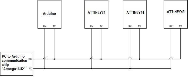
The four cicuits were Arduino ,ATTINEY84,ATTINEY44,ATTINEY45 each one of them was defined by a adderes
The videos below show the idea in action
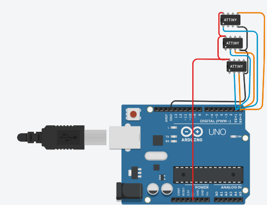
I was able to do all this br connecting the Arduino using the usb cable to communicate between the Arduino and PC directly then I connected all TX,RX pins in all four circuits together TX is the transmitter and RX is the receiver so when I send a value of 1 for example all the circuits will recive the same value but only the one that have the if statement for 1 will work and so on so when I also send 3 all the cicuits will receive it but only the one with if condition will work so By this method I can control switching ON and OFF in all the circuits
What is UART
For the theory and explanation of how UART works I read this webpage Click Here
The UART protocol allows for two devices to communicate with each other. The protocol requires two wires between the devices that are communicating; one for each direction of communication. Each device has an independent transmit and receive module. These modules do not have to be in time with each other Click Here
This link Click Here gave a general understanding of UART and had a simple example in communicating with Arduino.
This link Click Here has more information about the serial communication It had some fun examples which I tried this enabled me be more familiar with serial output communication. And this video explains how to implement the UART Click Here
Circuit fabrication With ATTINEY84
I decided to build the circuit with a simpler micro controller that is solder able to me and easy to find faults, the foot print is a bit larger and also the pin spacing is doable for me. below is the pinout diagram of the ATTINEY84 micro controller
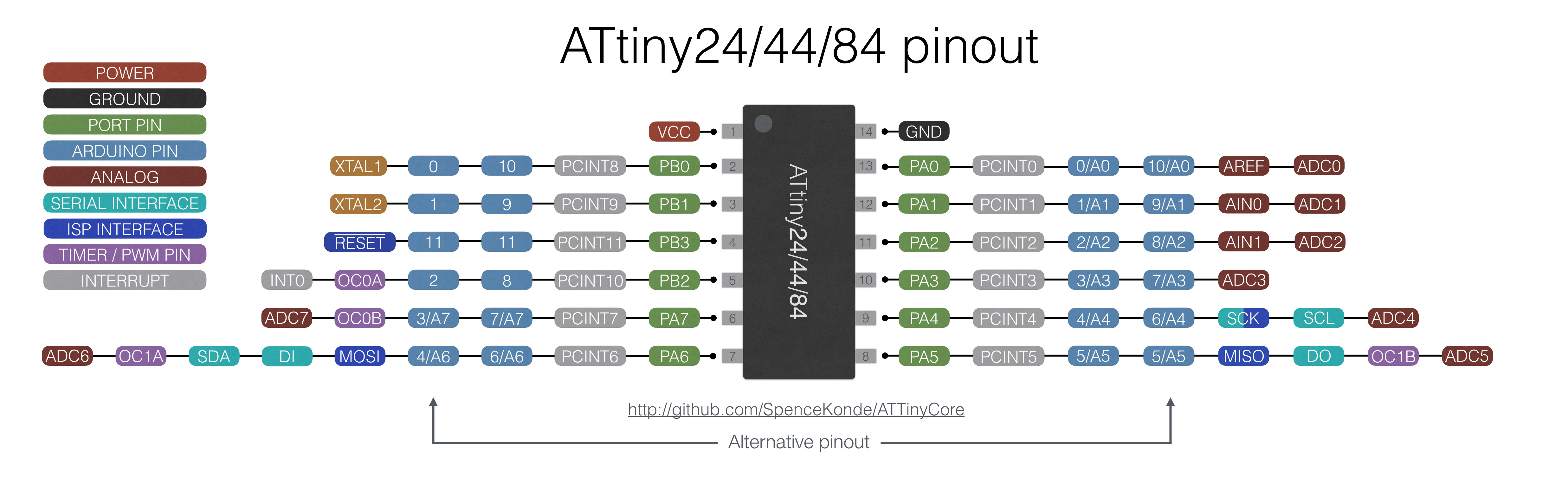
-for further information Data sheet ATTINEY84
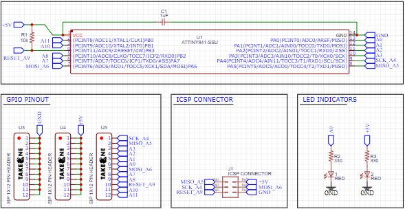
Drawing The Schematic
I put ATTINY84 with (2) led and (2) resistor, (1) capacitor with pin header
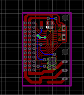
Drawing The PCB
I arranged the pieces
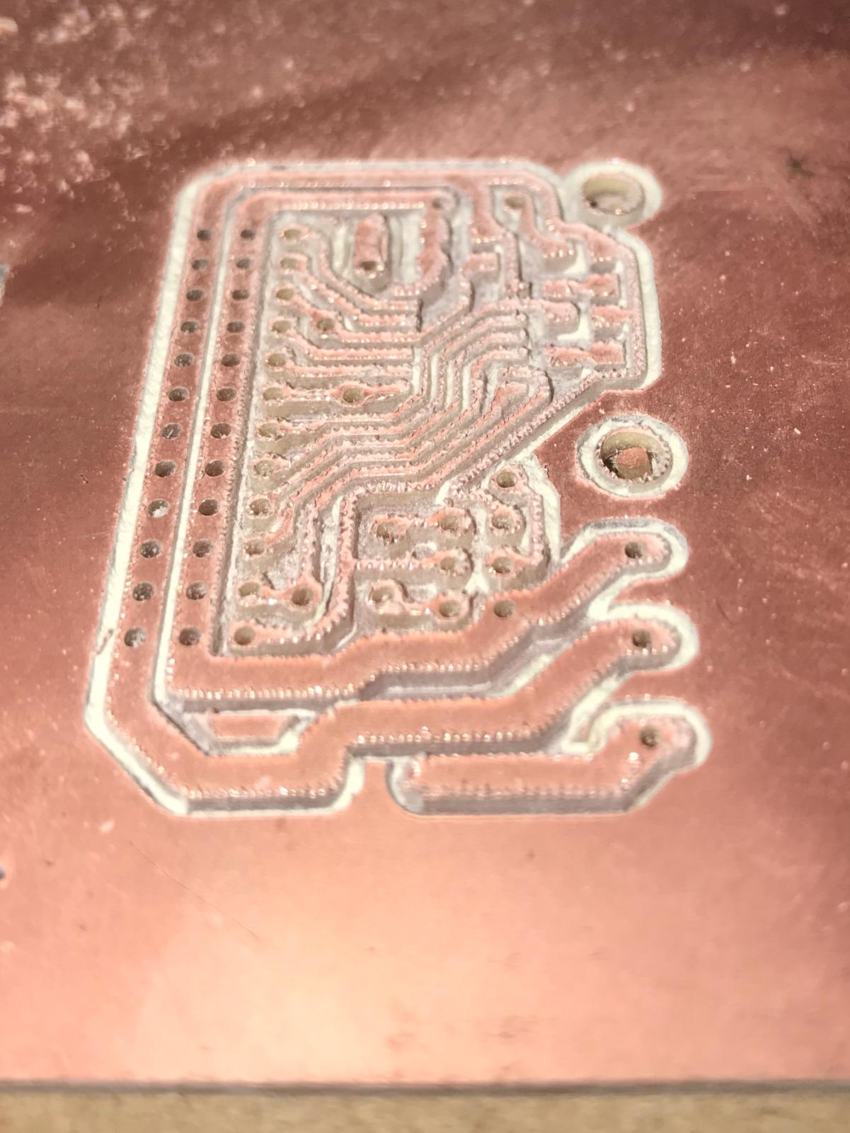
Milling & Soldering
I used a 1/64 mill bit
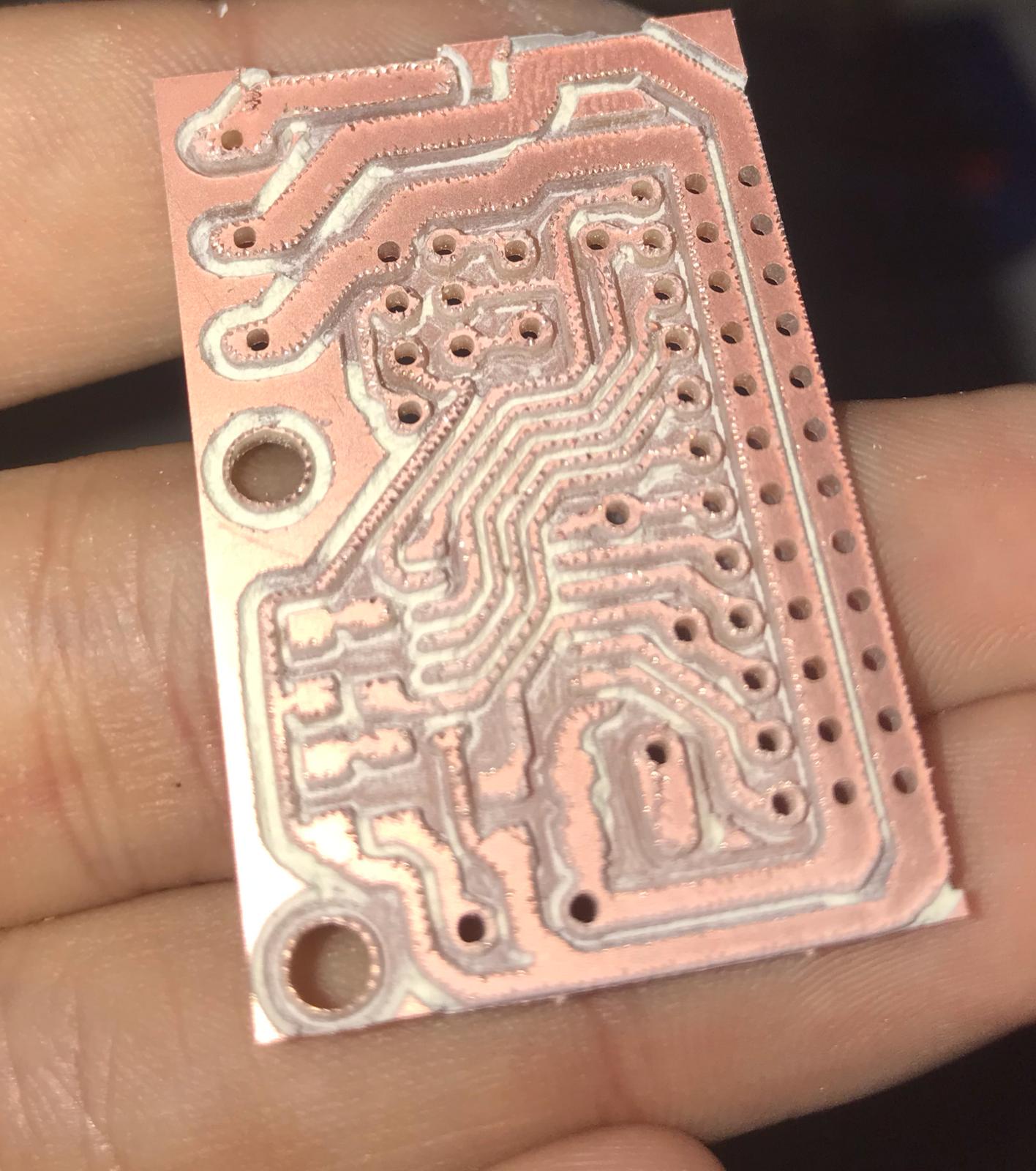
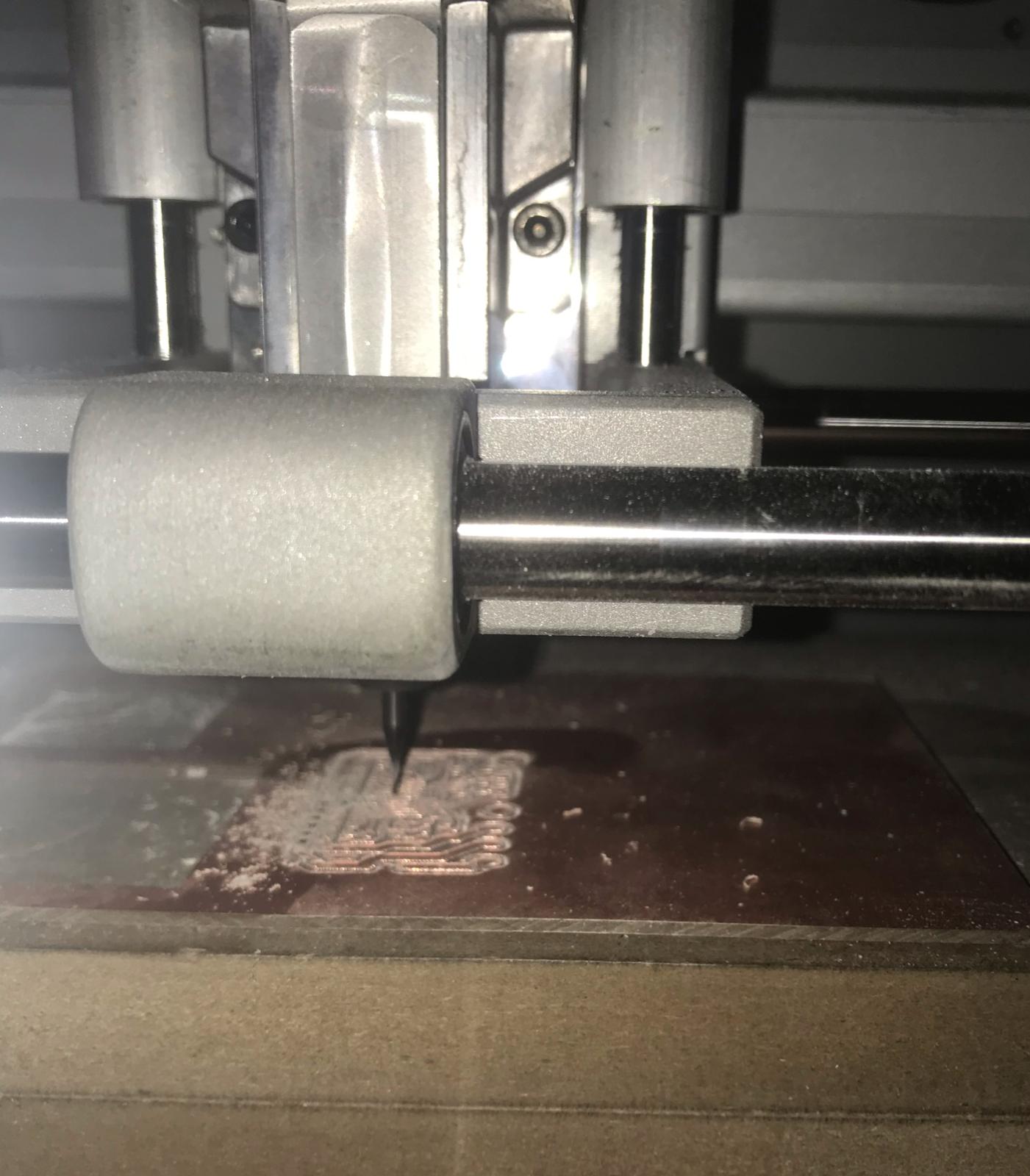 Result after digging the circuit and now I’m going to put in a 1/32 mil bit to cut out line .
After digging the circuit I cleaned the circuit from impurities
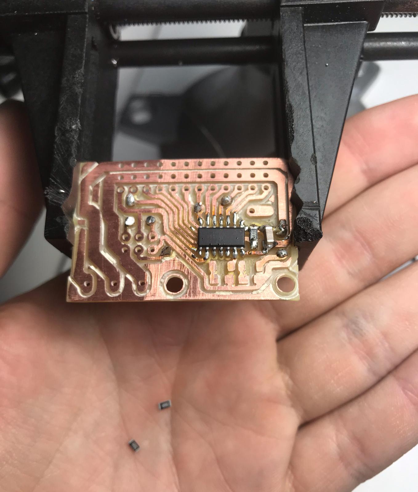
Here, I am doing a soldering for the microcontroller and the LED
- I did the same previous steps drilling the circuit and soldering the circuit
- You can check out this week to learn how you can do a Circuit Click Here
Testing my new circuit
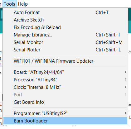
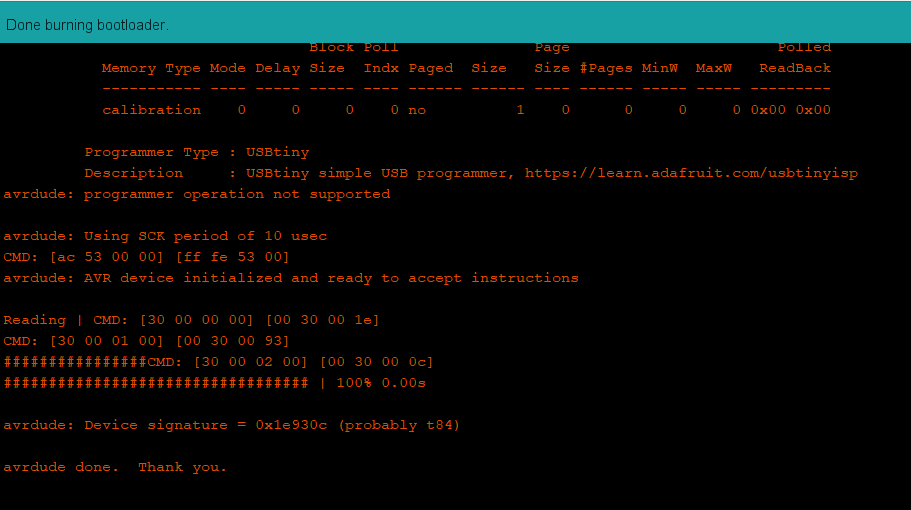
This is the result of a blink test code this means that my new board is working ,I had to burn the bootloader first

Wireing
For the wiring I had to connect the USB cable to the Arduino and three wires between the boards which is TX,RX,common GND and VCC
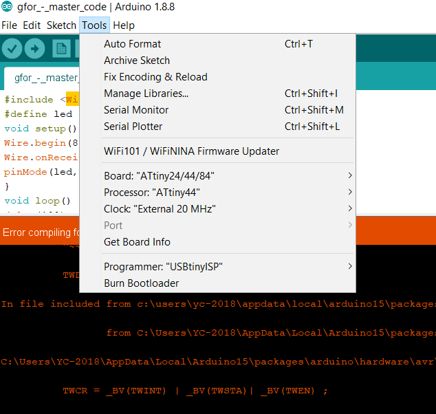
programming the four circuits
Code
The communication way was using serial the main thing that was happening is that when I send a 1 for example circuit ones LED will turn ON ONLY and if I send 1 again it will turn OFF this is also applied to other circuits so when I send 2 circuit 2 ONLY LED will turn ON also if I send 3 and 4.
so when I send a value of 1 in serial monitor for example all the circuits will recive the same value but only the one that have the if statement for 1 will work and so on so when I also send 3 all the cicuits will receive it but only the one with if condition will work so By this method I can control switching ON and OFF in all the circuits
Node one
This is the code for the Arduino code
#include <SoftwareSerial.h>
SoftwareSerial mySerial(PA1,PA0); //RX, TX
int v=0;
int nodeid=1; //the id
#define led 13  // the led pin
bool ledStatus=0;  //the status of the led


void setup() {
  Serial.begin(9600);
  pinMode(led, OUTPUT); // white led
}

void loop() {
  while (Serial.available () == 0 ) {}
  v = Serial.parseInt();
  Serial.println(v);
  if(v == nodeid && ledStatus ==0 )
{
  digitalWrite(led,HIGH);
  ledStatus=1;
}
else if (v == nodeid && ledStatus ==1 )
{
  digitalWrite(led,LOW);
  ledStatus=0;
 }
}
Node two
This is the code for the ATTINEY84
#include <SoftwareSerial.h>  //
SoftwareSerial mySerial(PA1,PA0); //RX, TX
int v=0;
int nodeid=2; //the id
#define led 3  // the led pin
bool ledStatus=0; //the status of the led


void setup() {
  mySerial.begin(9600);
  pinMode(led, OUTPUT);
}

void loop() {
  while (mySerial.available () == 0 ) {}
  v = mySerial.parseInt();
  mySerial.println(v);
  if(v == nodeid && ledStatus ==0 )
{
  digitalWrite(led,HIGH);
  ledStatus=1;
}
else if (v == nodeid && ledStatus ==1 )
{
  digitalWrite(led,LOW);
  ledStatus=0;
 }
Node three “Detailed explanation”
This is the code for the ATTINEY44
#include <SoftwareSerial.h> //This to include the software serial beacause the attinies dont have a chip to communicate as "hardware serial as arduino"

SoftwareSerial mySerial(PA1,PA2); //RX, TX            //here we set the pins for communication
int v=0;
int nodeid=3; //the id
#define led 0                                        //here we set the pins for LEd
bool ledStatus=0;                                    //the status of the led if it is ON or OFF


void setup() {
  mySerial.begin(9600);                              //Enable or start the serial baud rate
  pinMode(led, OUTPUT);                              //Set LED to OUTPUT
}

void loop() {
  while (mySerial.available () == 0 ) {}             //While the serial is working "available" recive data from
                                                       what ever it gives as numbers or so
  v = mySerial.parseInt();
  mySerial.println(v);
  if(v == nodeid && ledStatus ==0 )                   //If what has been recived from the serial is equal to its
{                                                       number or address and the led status is OFF then open
                                                        the LED
  digitalWrite(led,HIGH);
  ledStatus=1;
}
else if (v == nodeid && ledStatus ==1 )               //If what has been recived from the serial is equal to its
                                                       number or address and the led status is ON then close
                                                       the LED
{
  digitalWrite(led,LOW);
  ledStatus=0;
 }
}
The last part of the code is to verify if the led is off to open it and if it is on to close it
Node four
This is the code for the ATTINEY45
#include <SoftwareSerial.h>
SoftwareSerial mySerial(PA1,PA0); //RX, TX
int v=0;
int nodeid=4; //the id
#define led 3  // the led pin
bool ledStatus=0; //the status of the led


void setup() {
  mySerial.begin(9600);
  pinMode(led, OUTPUT);
}

void loop() {
  while (mySerial.available () == 0 ) {}
  v = mySerial.parseInt();
  mySerial.println(v);
  if(v == nodeid && ledStatus ==0 )
{
  digitalWrite(led,HIGH);
  ledStatus=1;
}
else if (v == nodeid && ledStatus ==1 )
{
  digitalWrite(led,LOW);
  ledStatus=0;
 }
}