7. Electronics design
group assignment page
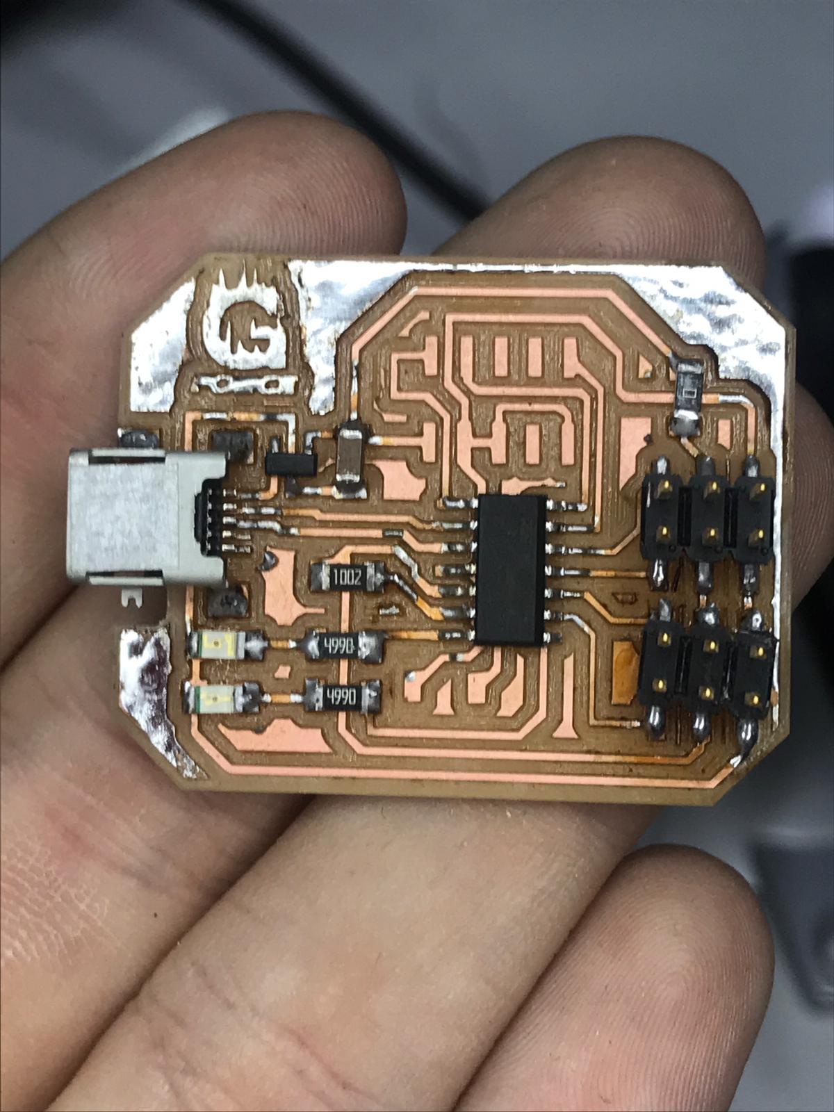
Circuit (1) SAM D11c
EAGLE
- Introduction to Eagle After downloading the program, I downloaded the library of the pieces I needed EAGLE
Tutorial Eagle
- These were the three tutorials that helped me
Tutorial 2 Printed Circuit Board Layout
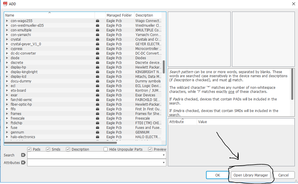
Library
The goal of the library is to add electronics to the software so that I can start designing I will connect those components together depending on the microcontrollere diagram and pinouts
The steps:
-
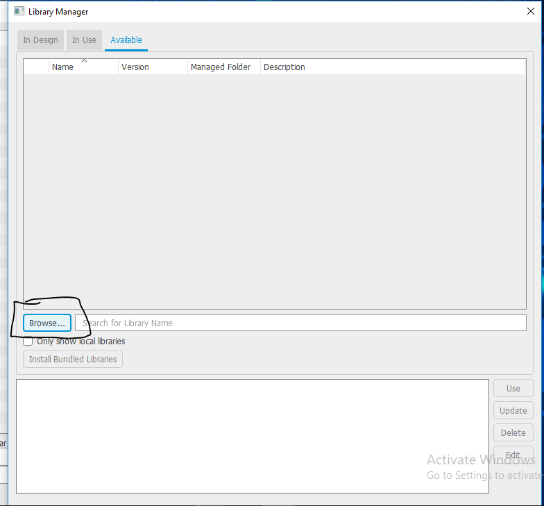
You open the libraries and add a new library
-
I downloaded the library
-
You choose the file
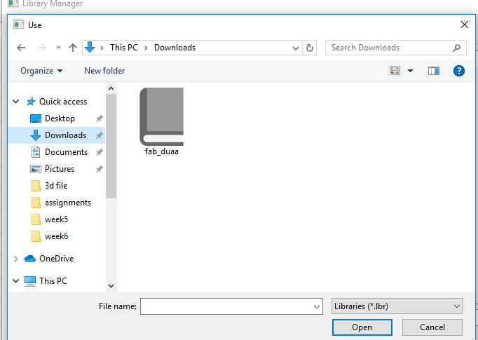
-
After I choose the file, it appears in the bar above
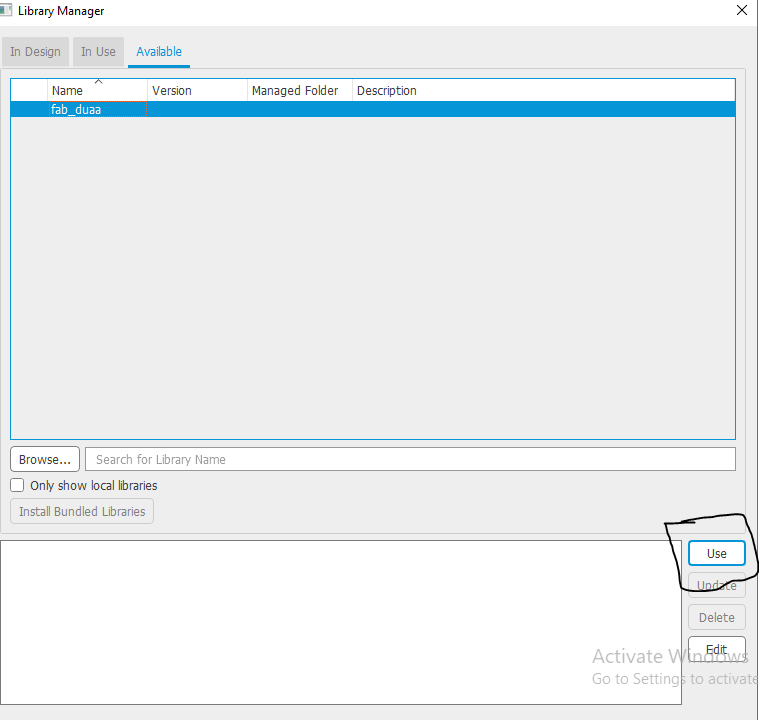
-
Schematic diagram “EAGLE”
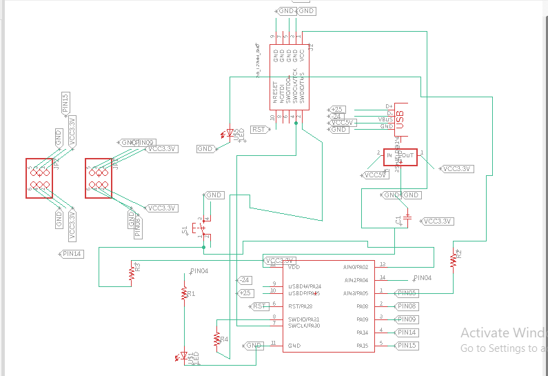
-
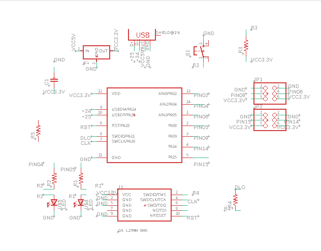
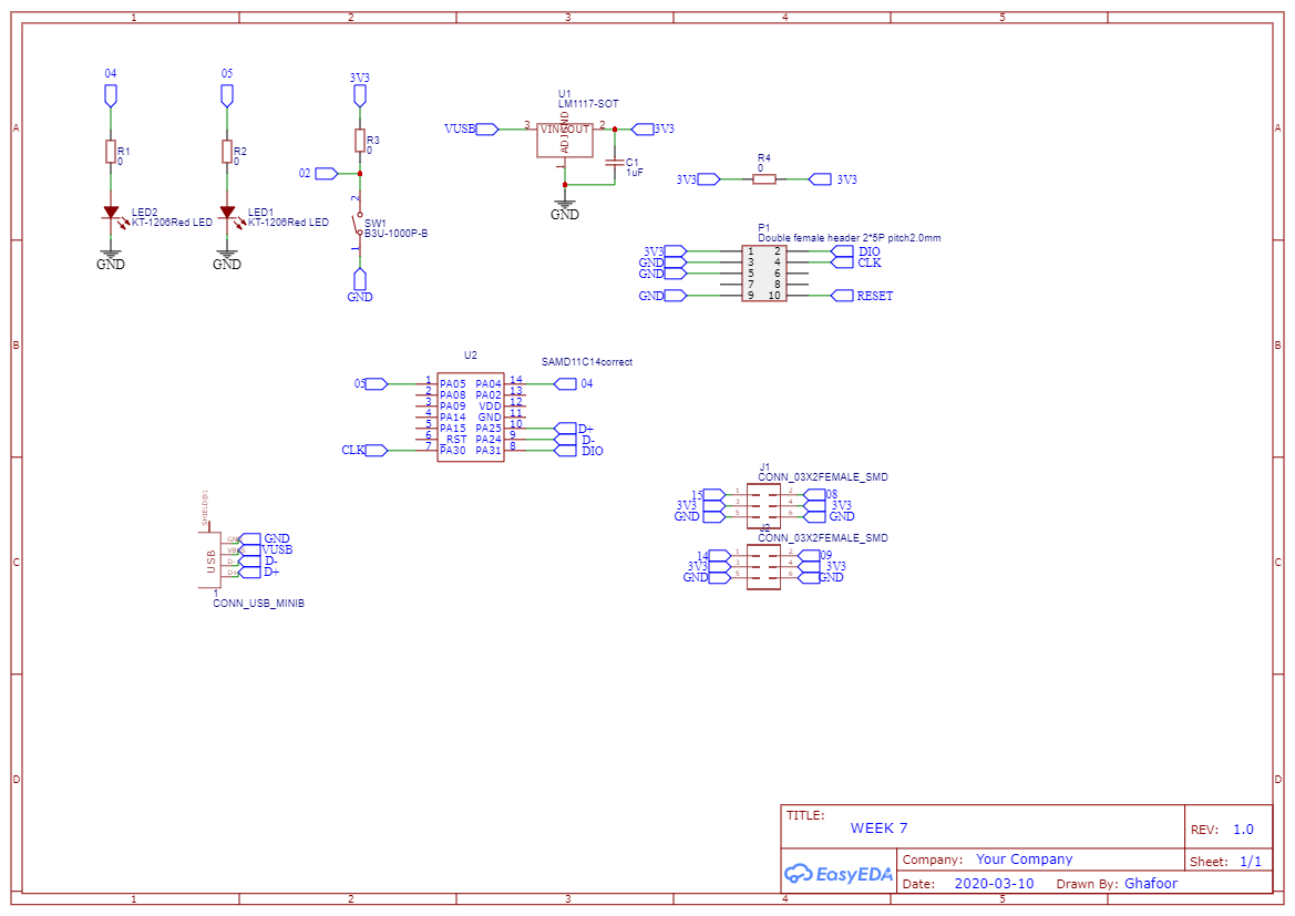
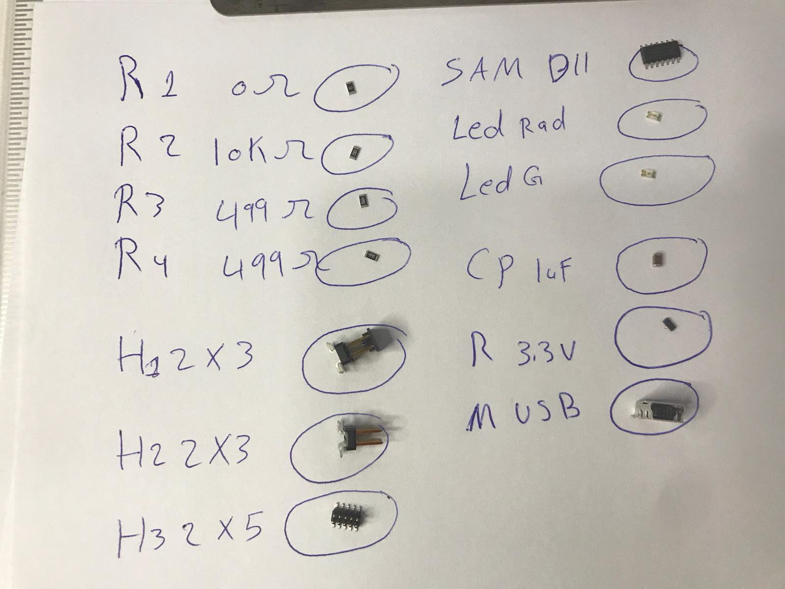
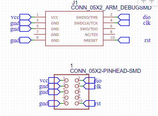
This is my circuit layout that I designed. According to the requirements, I have 2led, 5 resistors, capacitor, ic sam d11 and batten And Bin Hydar 2x3 Bin Hydar 2x5
-
I had some problems like some of my comptons were not present in the program so I downloaded a library with the pieces available in our lab
PCB design “EAGLE”
-
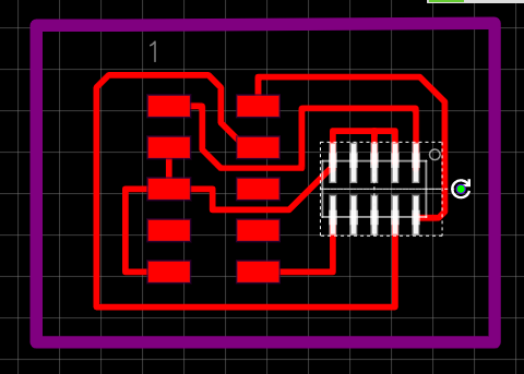
After I finished drawing the pieces, I started to arrange the pieces according to the nearest microcontrollers
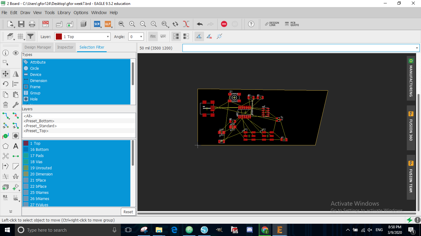
-
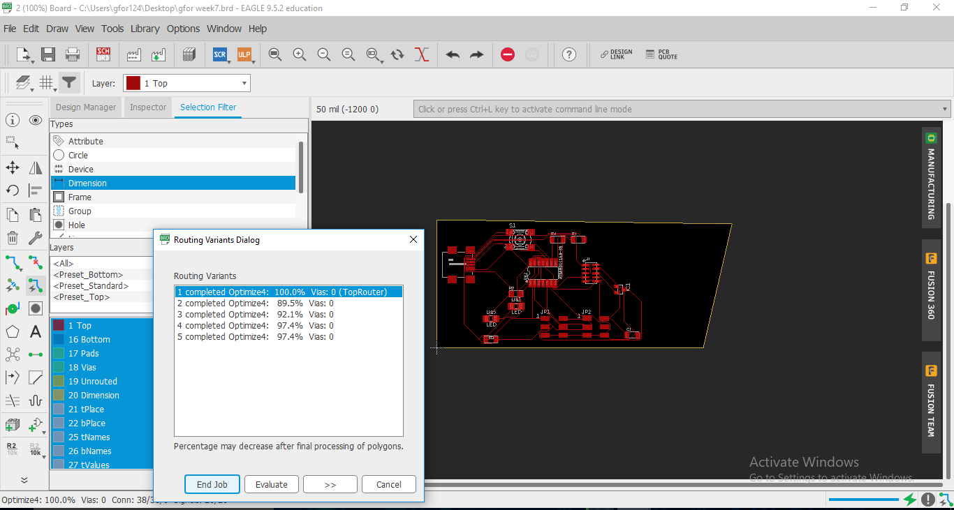
I chose this option to arrange the fonts automatically
-
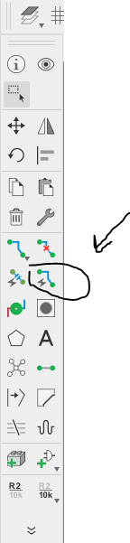
The option was not good because there are a lot of lost spaces so I connected the wires myself by tracing each line to be connected
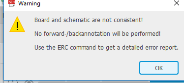
PCB problem after design “EAGLE”
-
This problem arose for me while I was designing the circus. The problem was that there was Bin Haidar that was upside down. I modified it so that I could design the circuit.
-
I drew the circuit again because many mistakes occurred, I erased it and made another circuit.
-
This was the new drawing
 Note
Note - After using it for 3 days I aws running out of time , I decided that I did not want to use eagle for the following reasons
- it was crashing alot
- I had a hard time getting some tools and I needed some time to find the tools I wanted to use
EasyEDA Tutorial
- In this video, I learned from this person how to use this software and how BCP works on it
Easy EDA
- I designed circuit again in this software after I had difficulties with EAGLE
- I used Easy eda, I am designing this circus because The software was easy to use and I could easily find all the tools I wanted to use
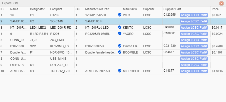
I counted the pieces that I would use in making the Circuit
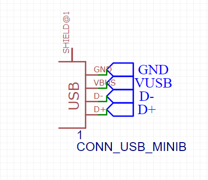
I set USB as the input power to circuit
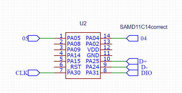
Here it looked at tagging for you to connect each other
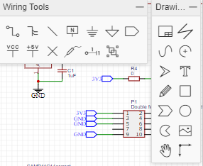
This is the toolbar that I used as I was designing the circuit and all tools were available and easy to find
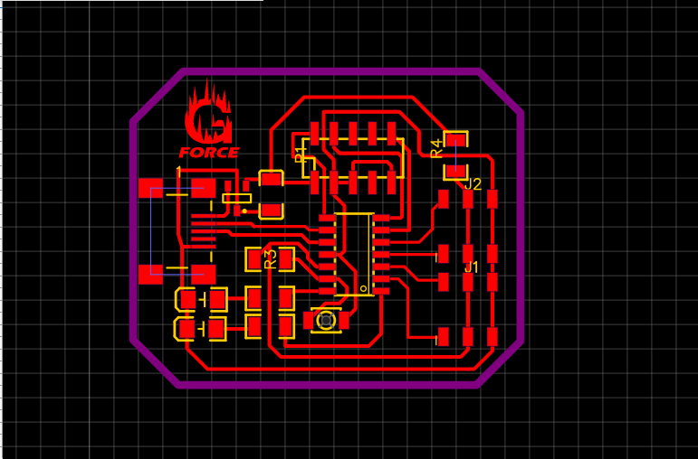
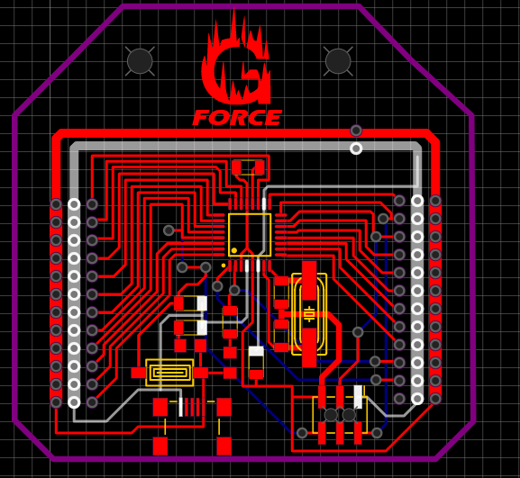
This is the circuit connection,Then design the PCB
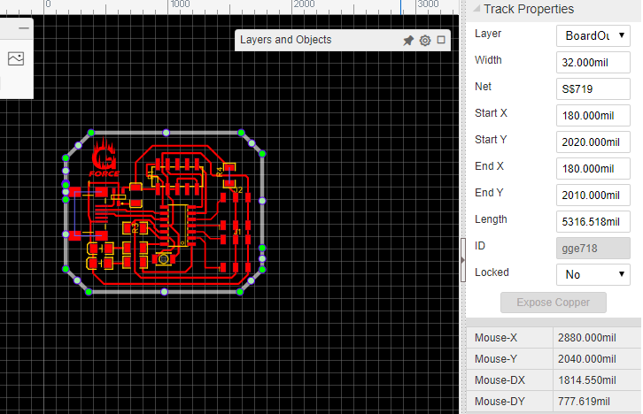
From here, I modified the line size according to the specifications that I want (32mil)
Here I have modified the inner lines (15mil)
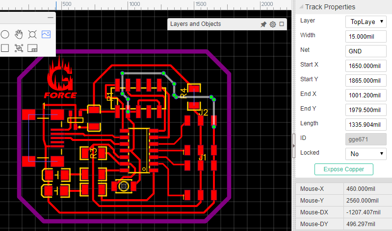
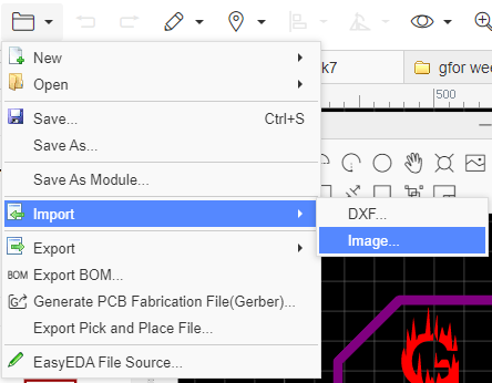
From here I added my logo
Hence the circuit is ready to be drilled
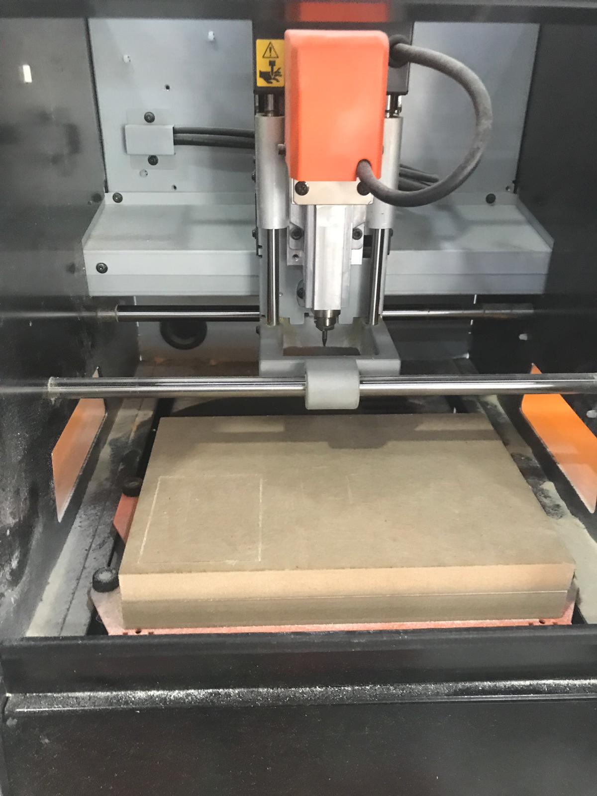
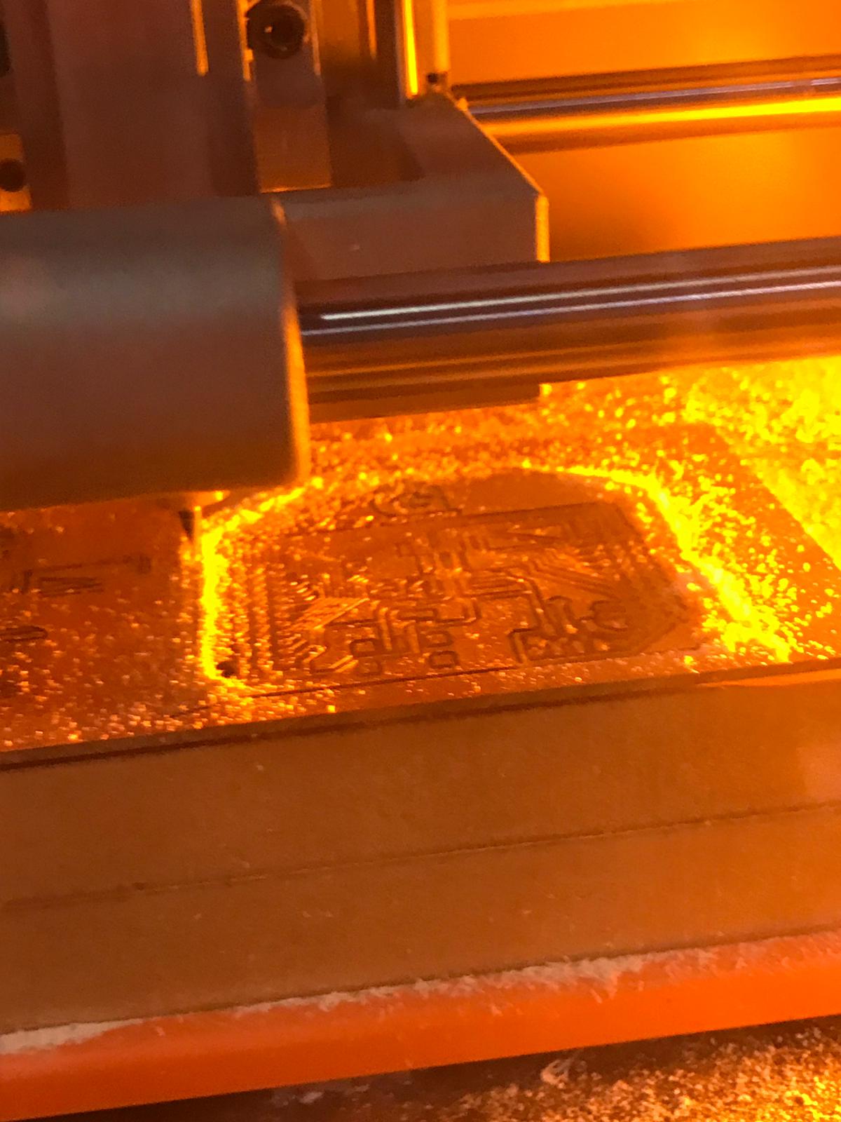
Milling the board
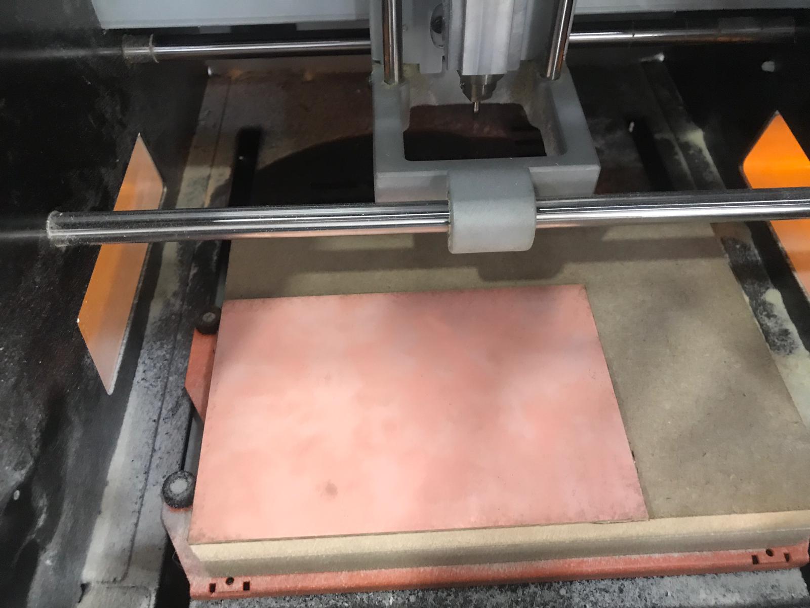
I followed the steps in week 5 for milling
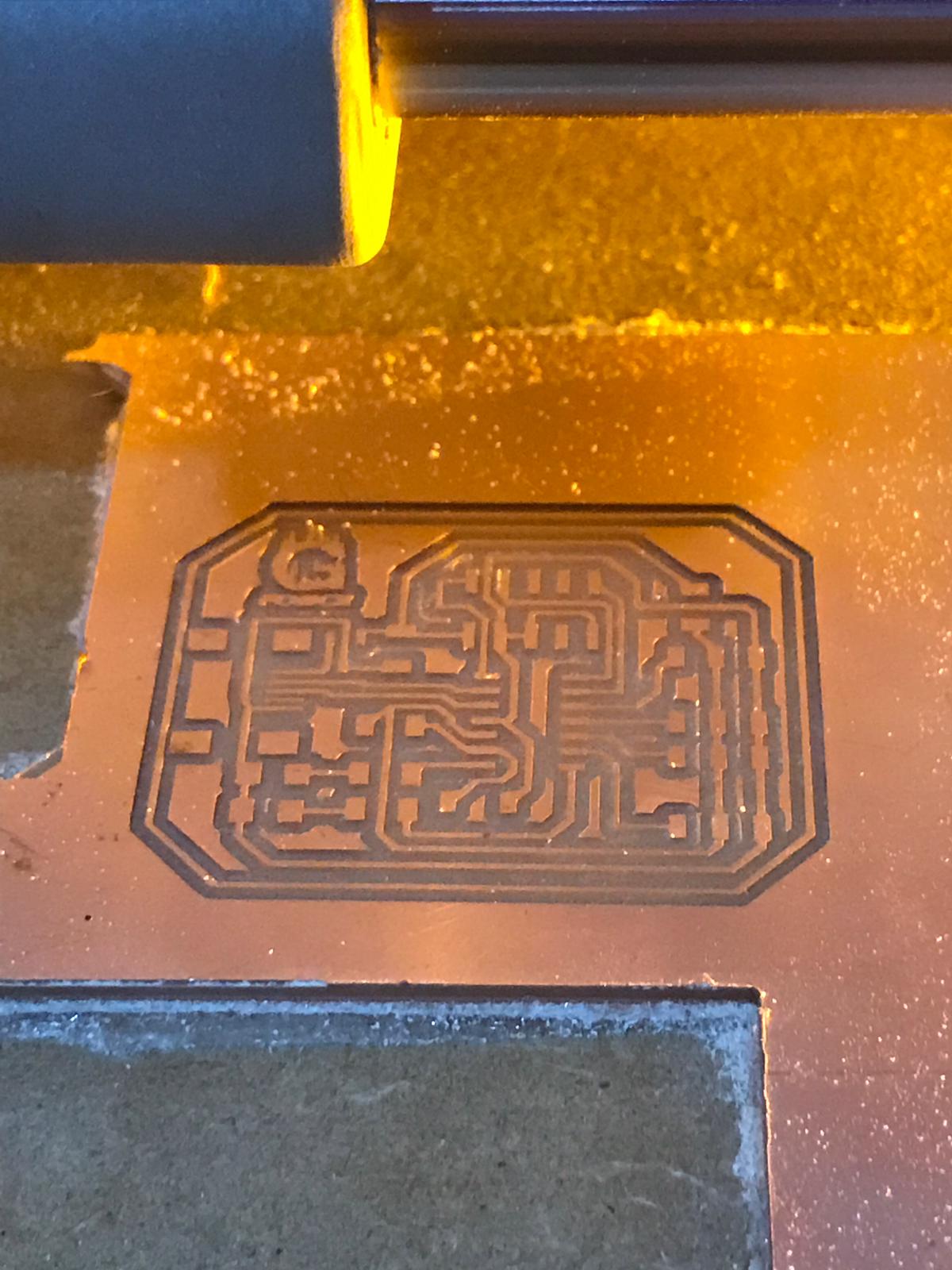
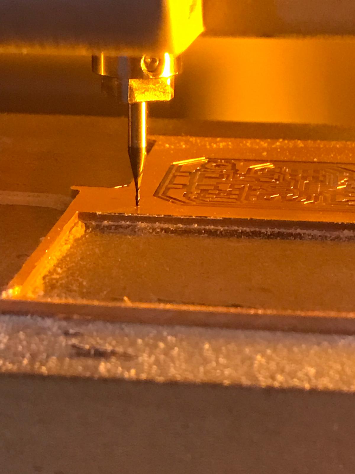
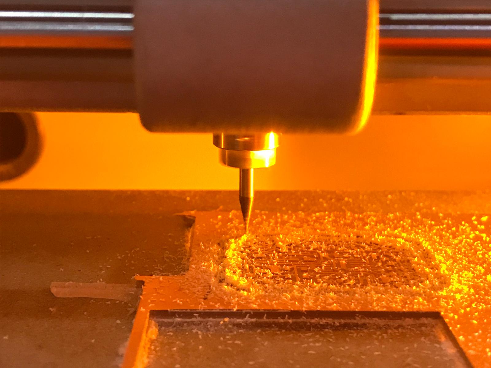
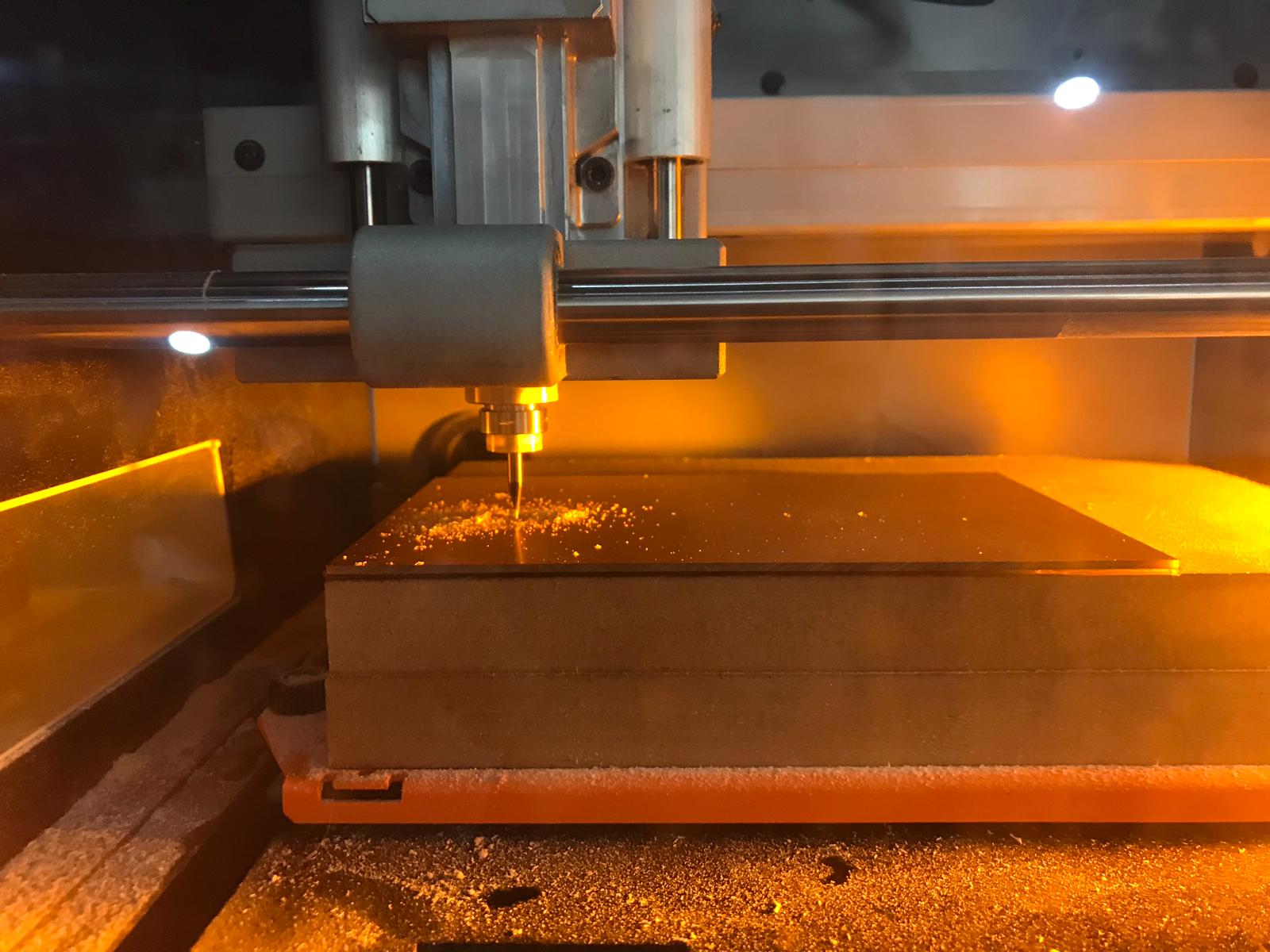
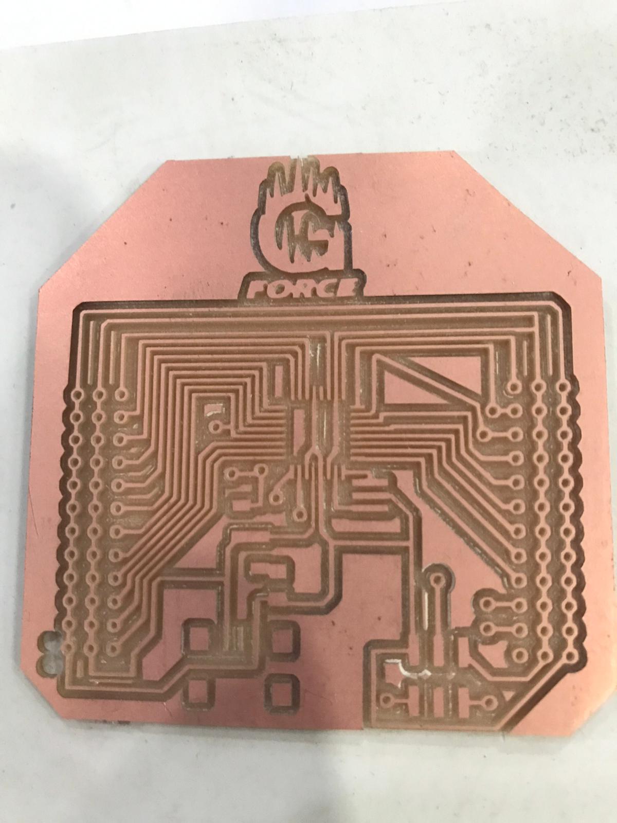
I started milling using the smaller drillbit 1/64 to mill the circut
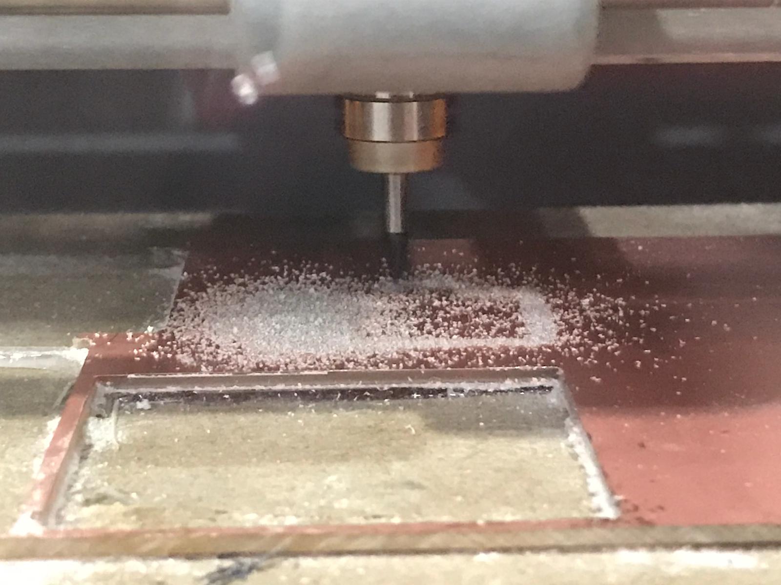
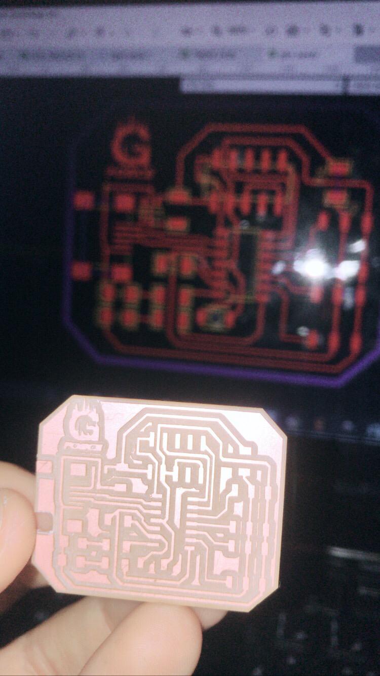
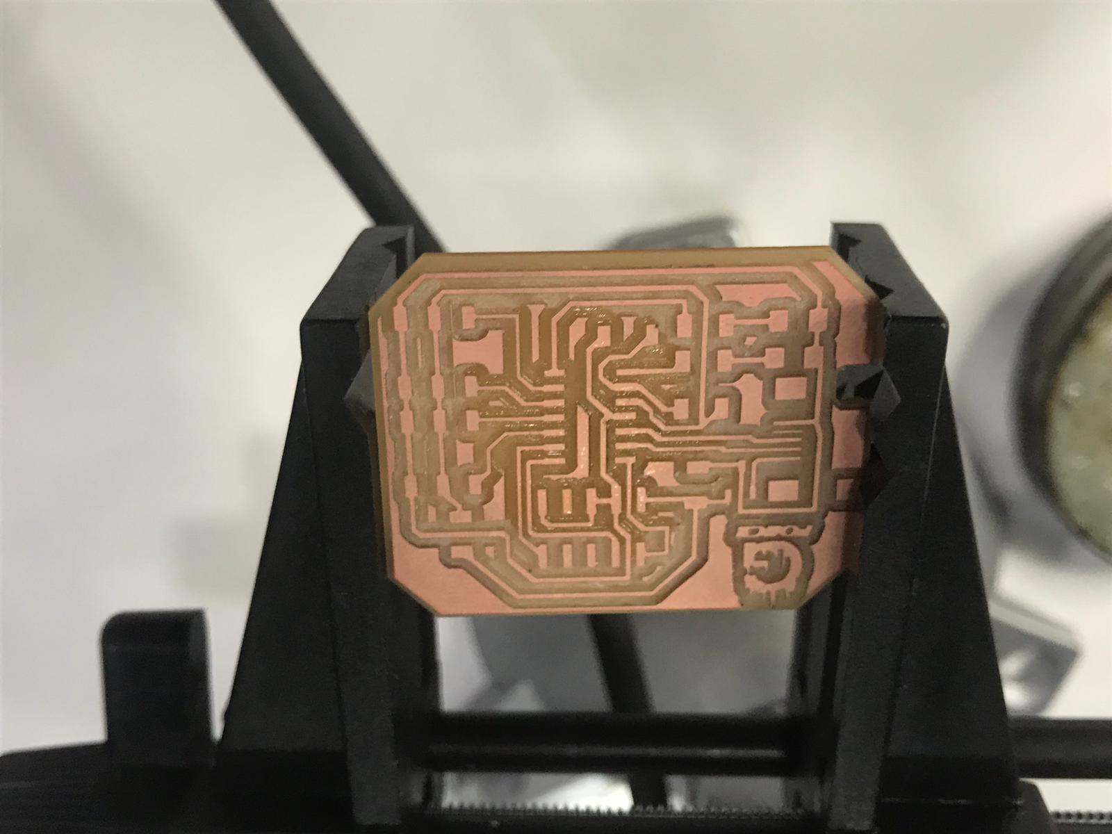
This is the result from it
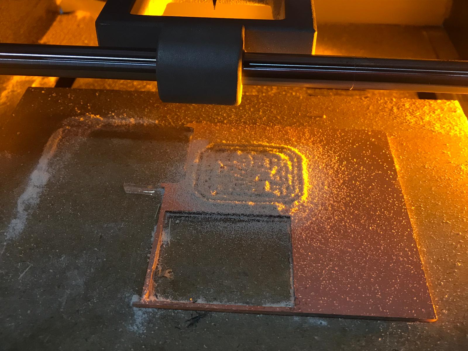
Then I changed the drill bit to 1/32 to cut out the board frame
This is the result from it
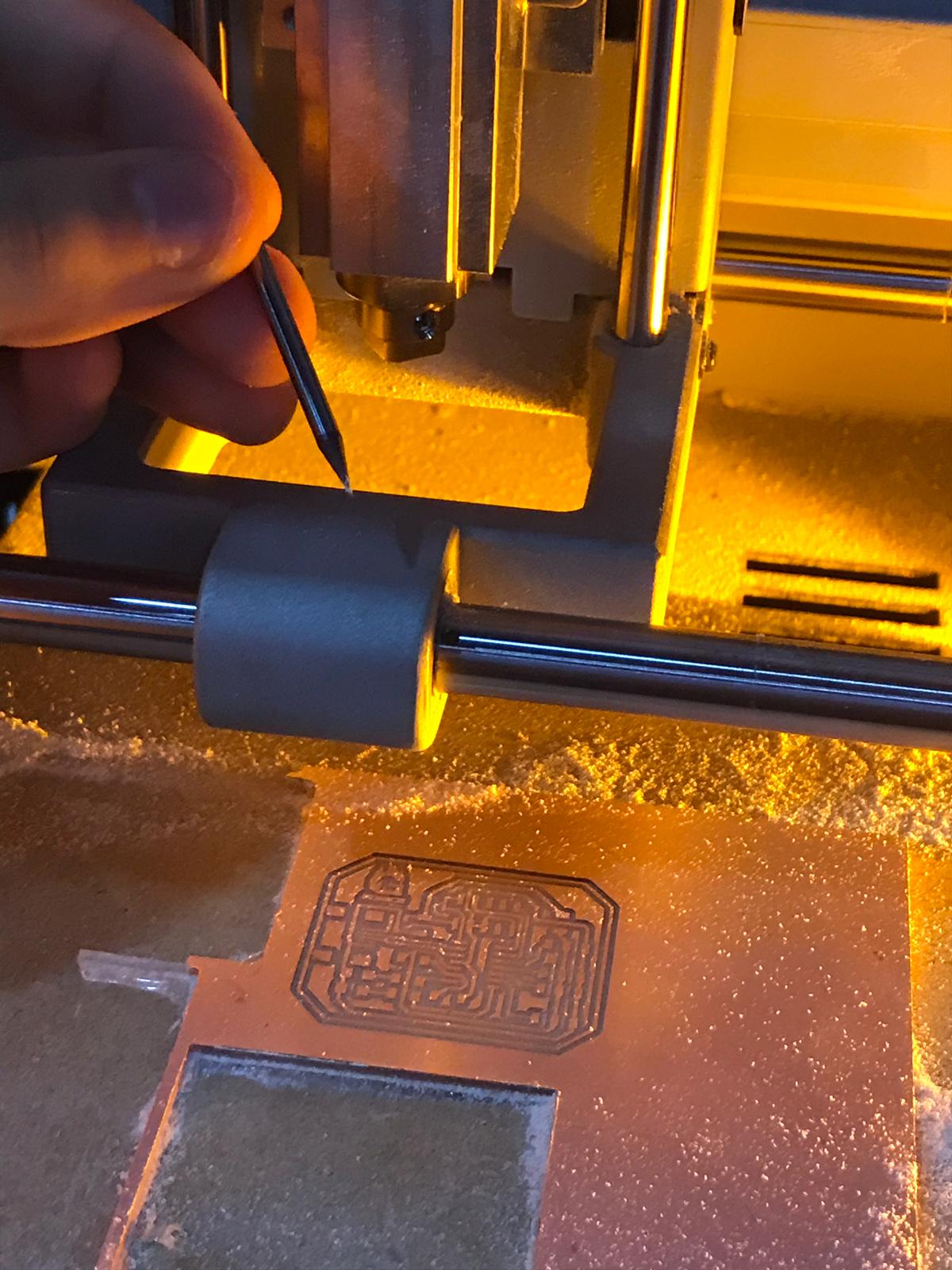
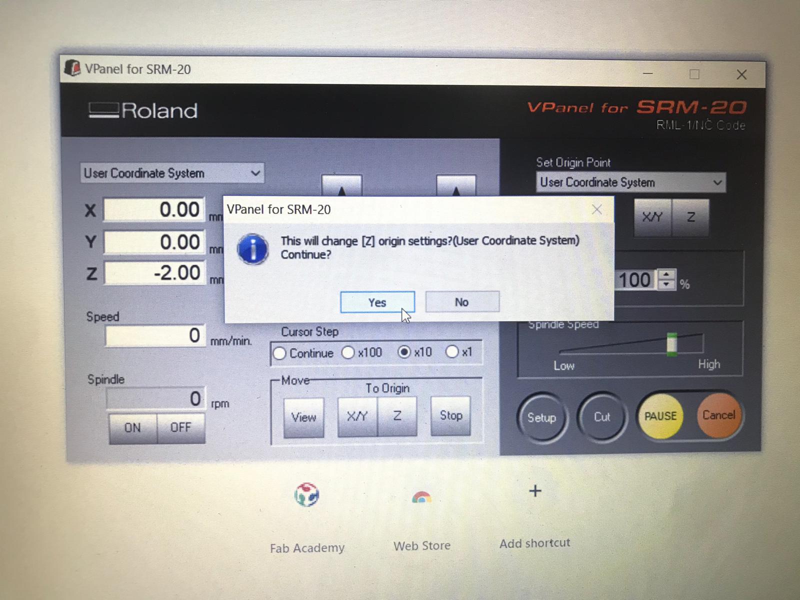
I set the zero for the Z axis
Then we started the milling
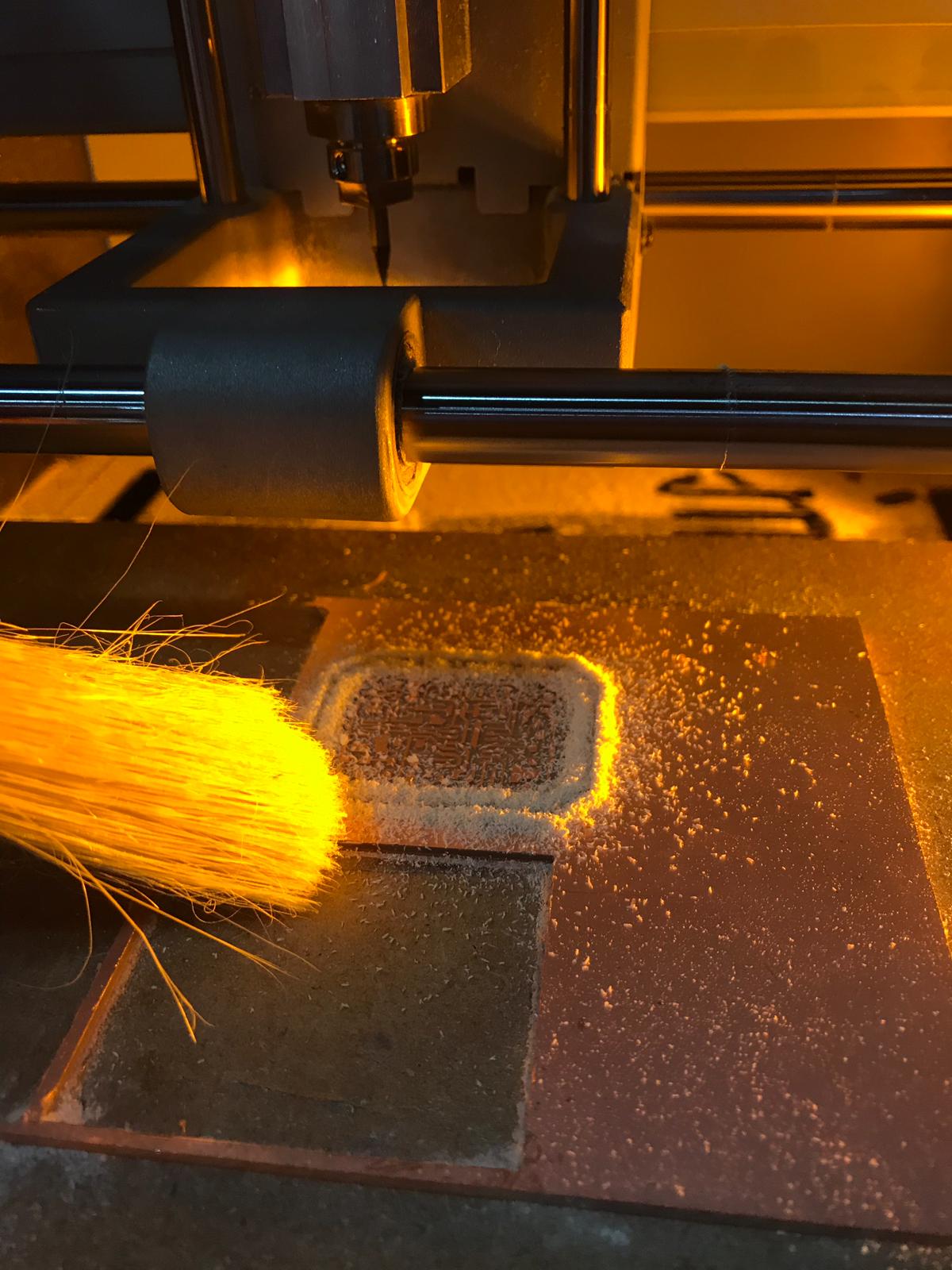
 I used a brush to clean it
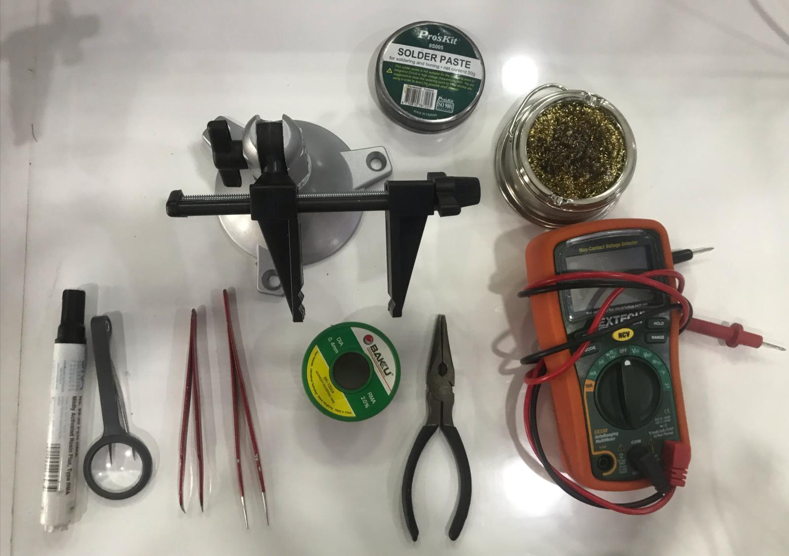
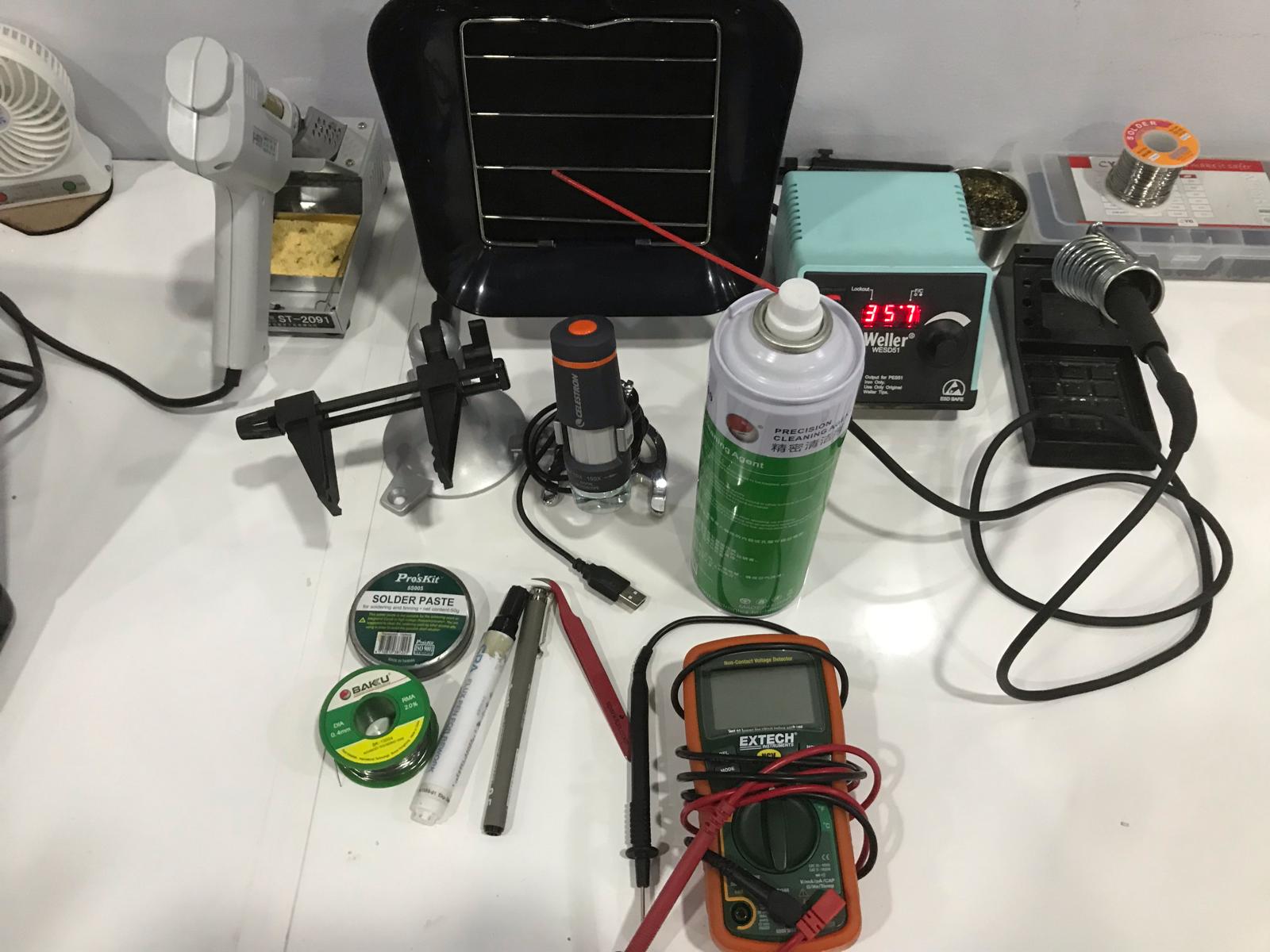
TOOLS USED for soldering
So I took out all tools I need such as multimeter plires holder soldeing iron and more
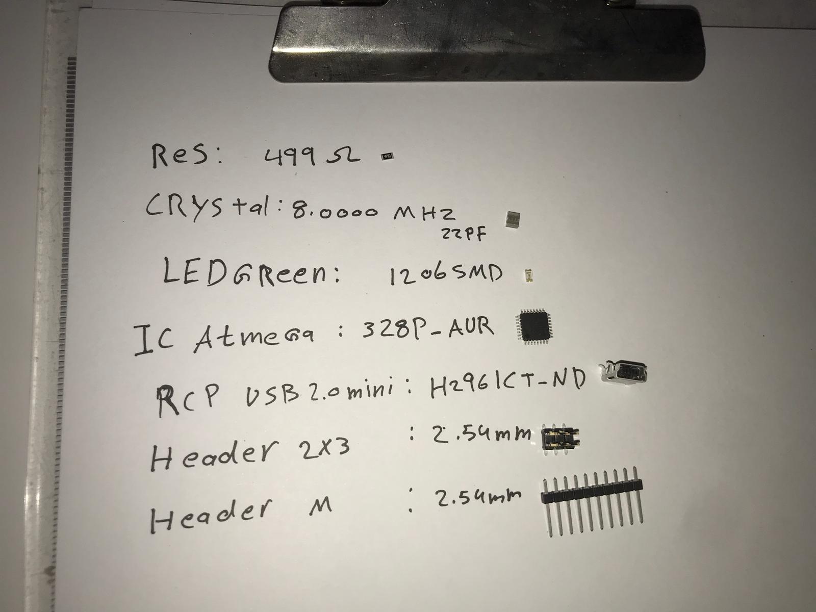
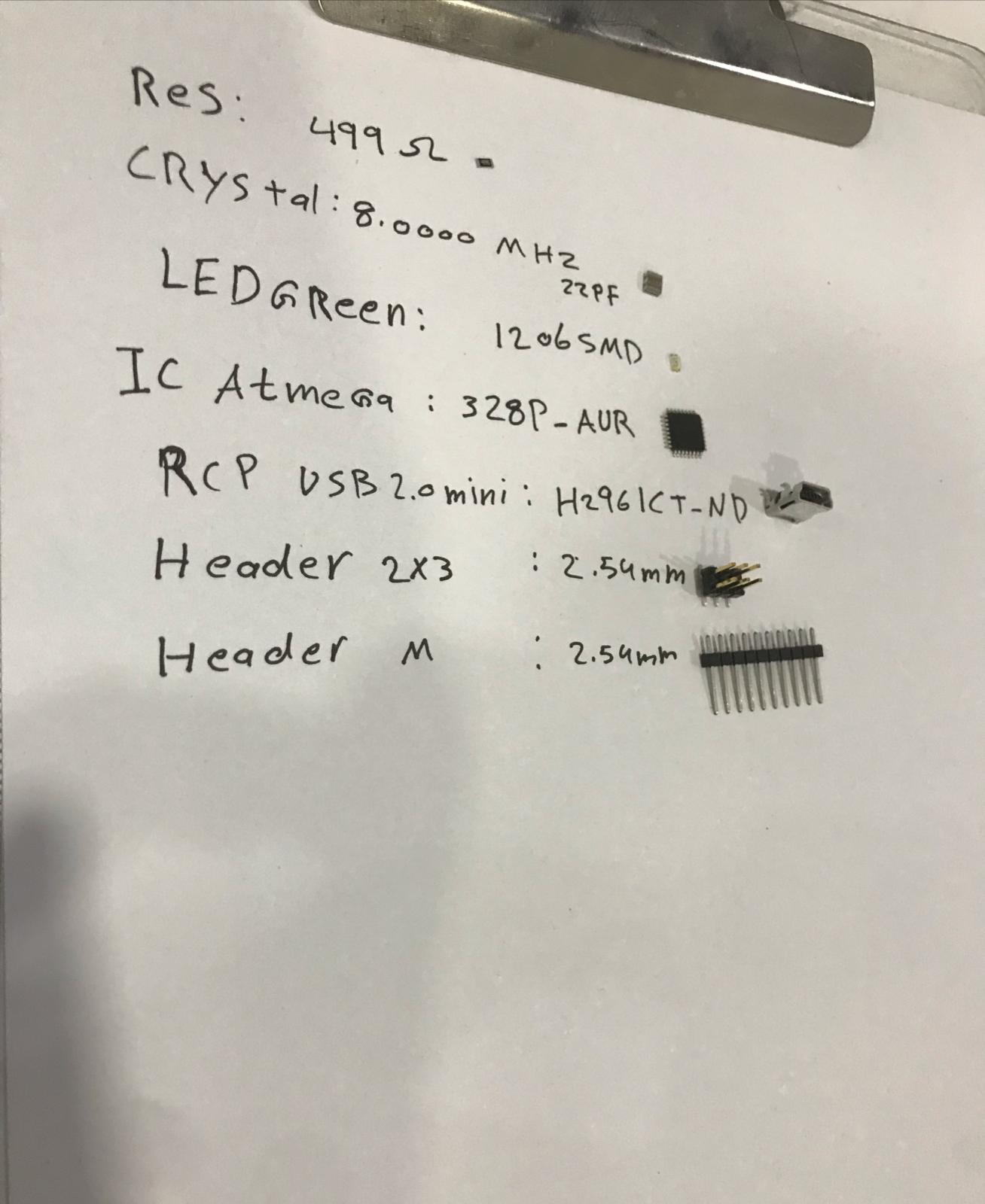
COMPONENTS USED
I took out all components I need so it get easier to solder them
Soldering
i used the holder to hold the circuit so I can solder it
This is a timelapse of me soldering the ciruit
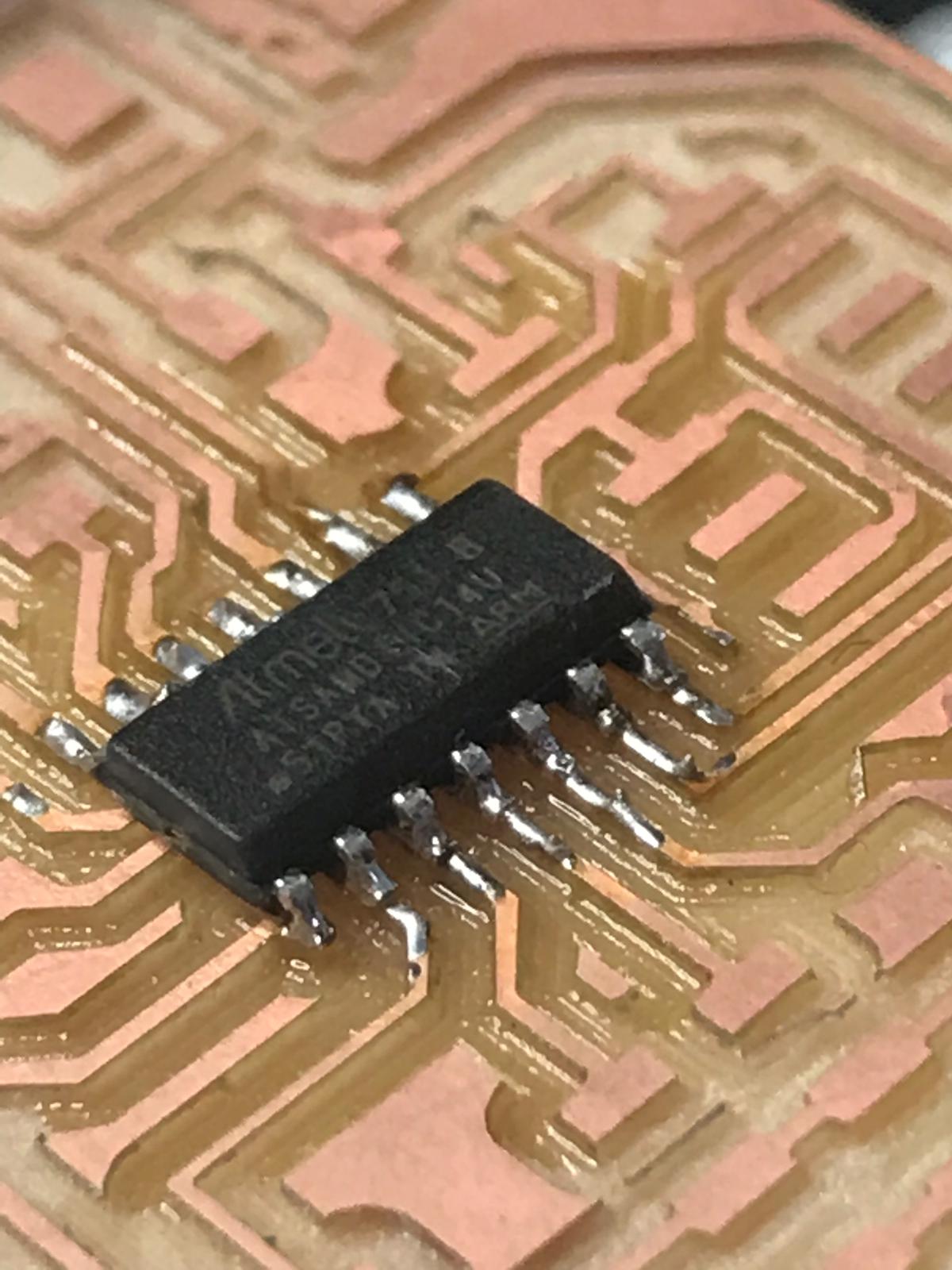
This is the microcontroller soldered in place
Problem
After I weld the pieces on the board I found that there was an error in the header and designed a piece to solve this problem for me
The circuit that will be installed on top of the other for me to program
Programming
I connected the circuit with the programmer
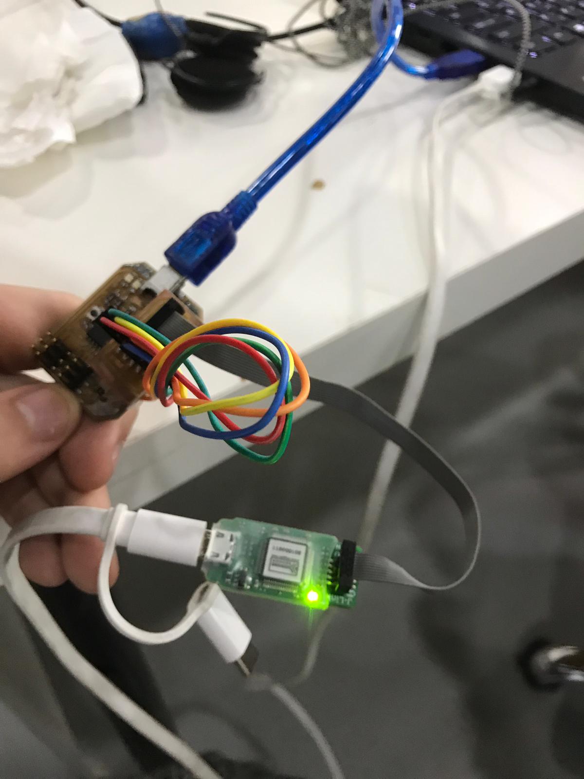
Here I connected the usb power cable
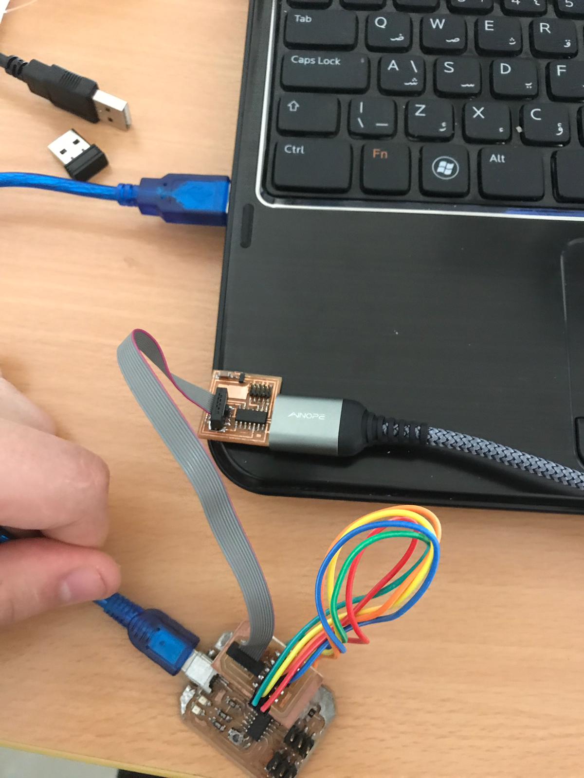
Here it is working by the bilk example
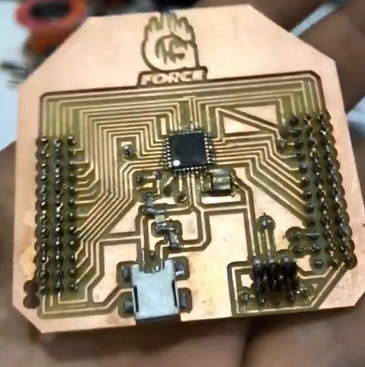
Circuit (2) AT MEGA328p
PCB design “AT MEGA328p”
Milling the board “AT MEGA328p”
using the same steps mentioned above I milled my Second pcb
I added double sided tape
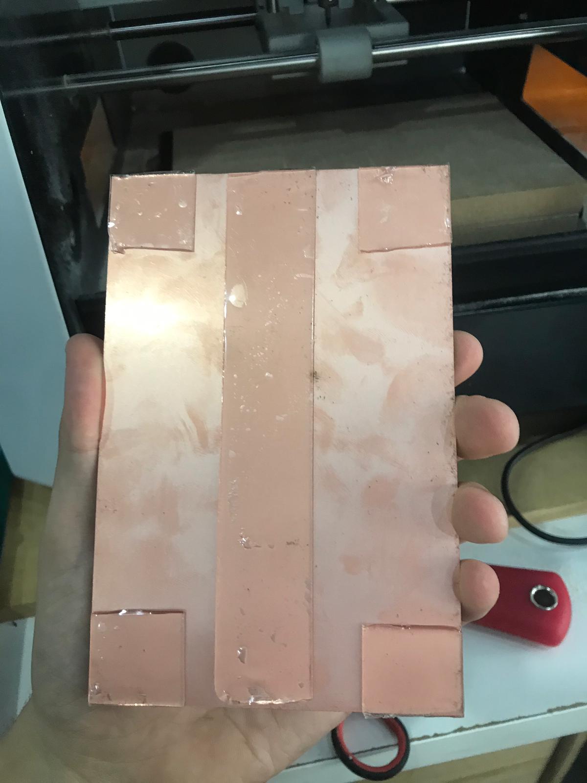
I fixed it on the bed
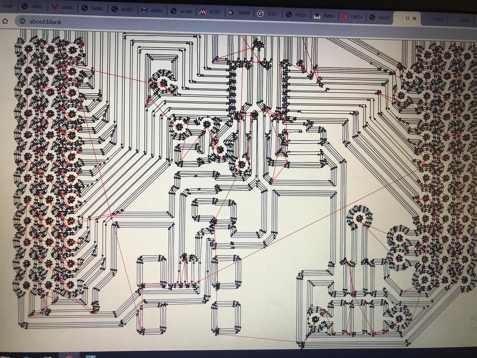
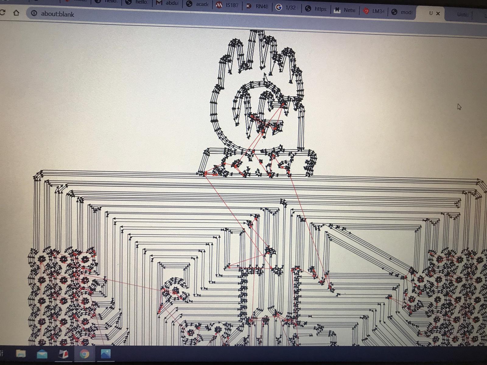
I created the toolpaths using fabmods
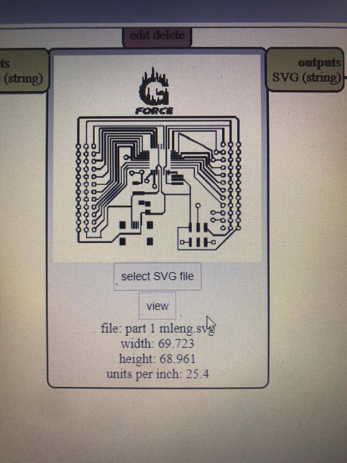
I set the Z axis origin to start from zero
The I started milling with 1/64 to do the traces lines for my design
Now its time for changing the millbit to 1/32
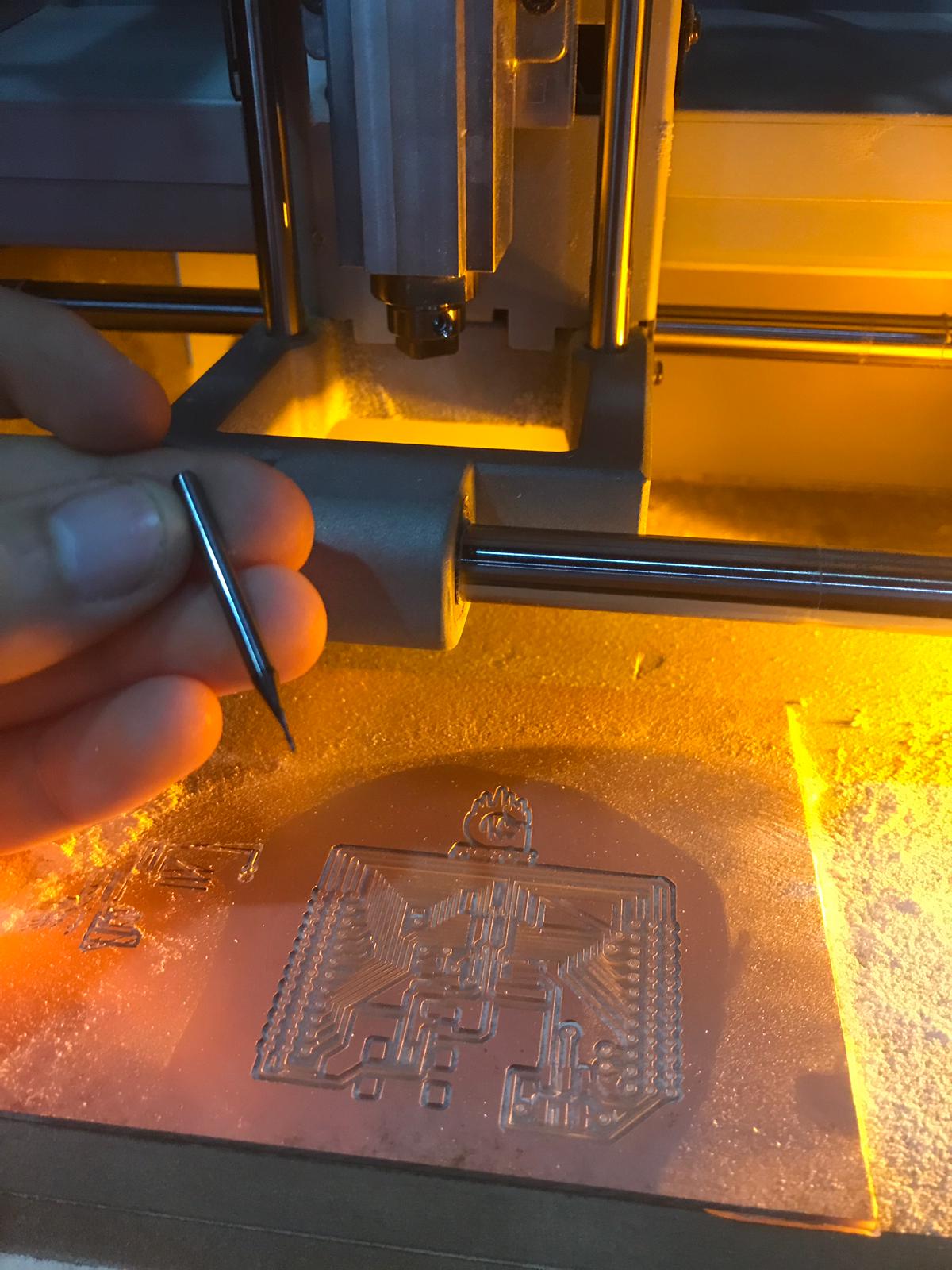
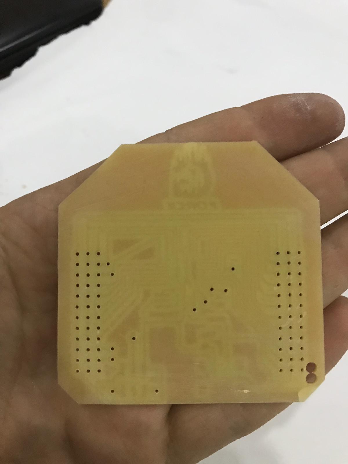
After cleaning this is the result
I used sanding paper to remove the copper layer
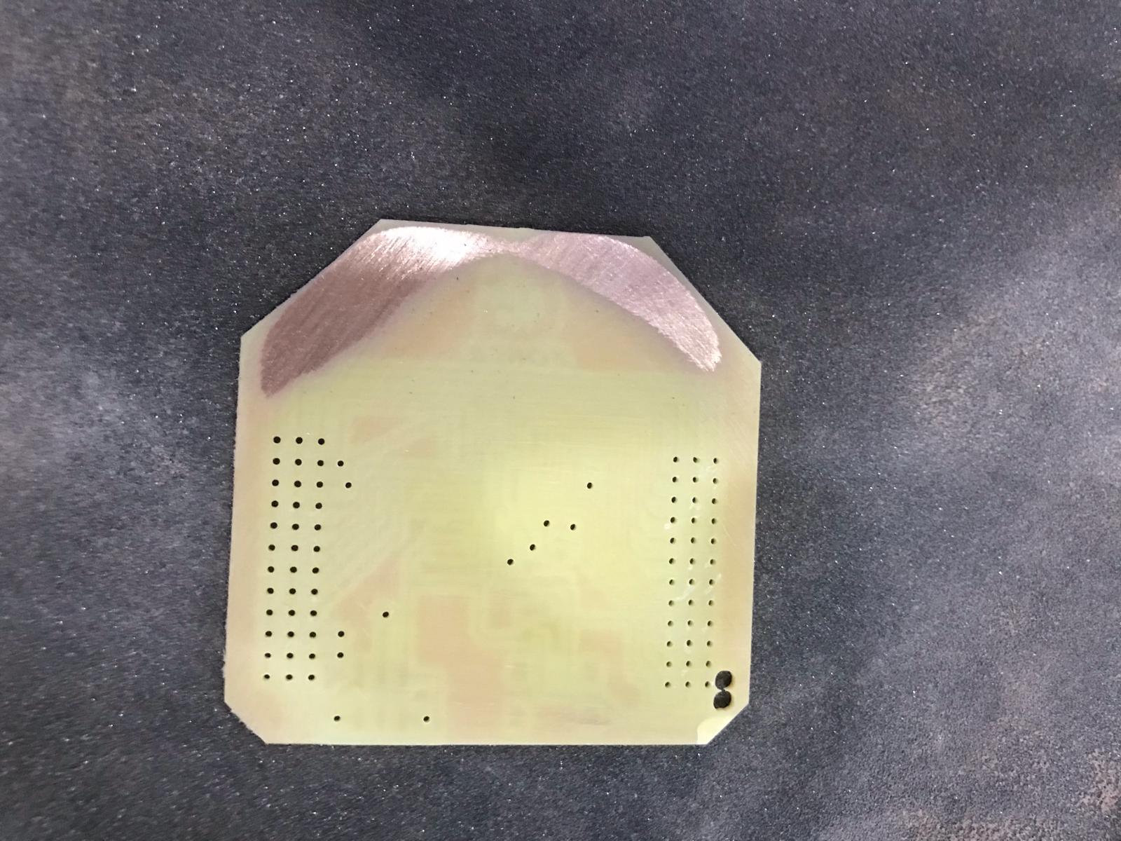
This is the result
TOOLS USED “AT MEGA328p” to solder
So I took out all tools I need such as multimeter plires holder soldeing iron and more
COMPONENTS USED “AT MEGA328p”
I took out all components I need so it get easier to solder them
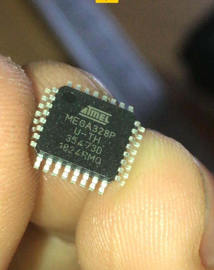
Soldering “AT MEGA328p”
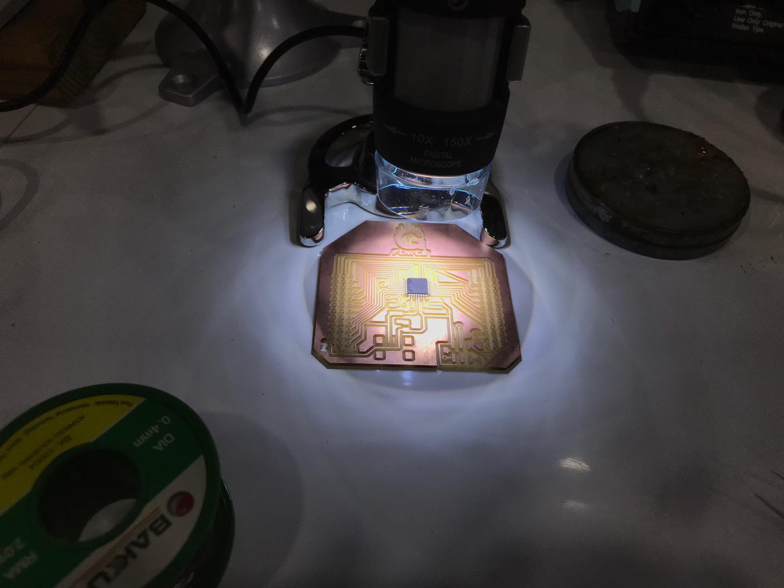
This the microcontroller
I used a camera focus to solder so I can easily solder
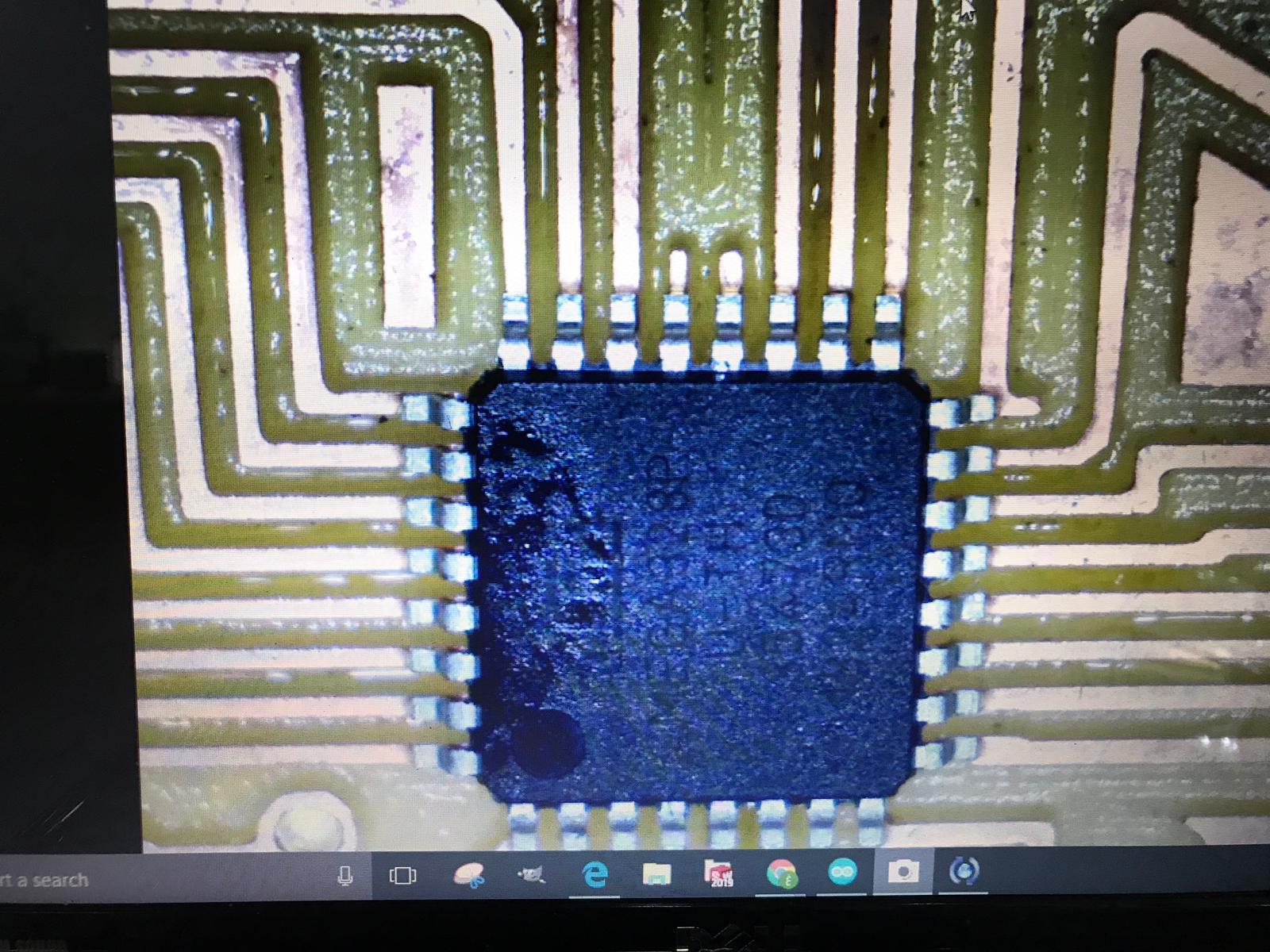
The camera had also light
Programming “AT MEGA328p”
These are the steps of programming