9. Embedded programming
group assignment page
Datasheet ATTINEY84
-
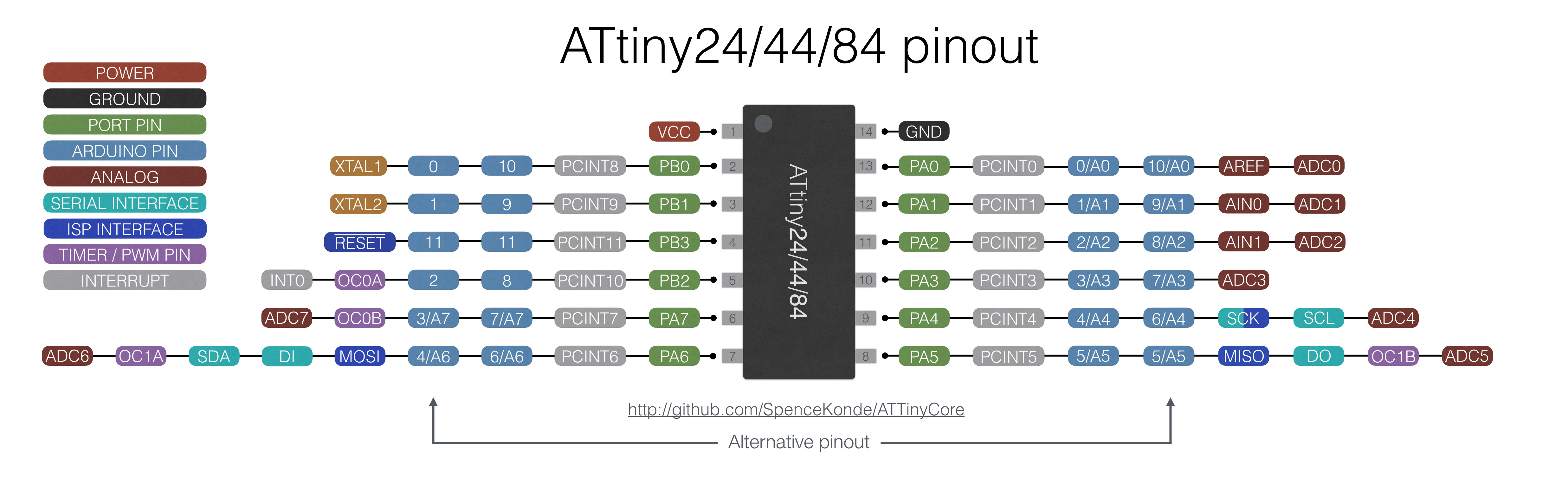
I decided to build the circuit with a simpler microcontroller that is solderable to me and easy to find faults, the footprint is a bit larger, and also the pin spacing is doable for me. below is the pinout diagram of the ATTINEY84 microcontroller.
-
In this microcontroller, I got to know more about pinout that contains 16 pin and I can program it in more than one program such as Atmel Studio and Arduino ide
-
I used the pins in programing the output(led ) & input (button)
-for further information Data sheet ATTINEY84
Circuit fabrication With ATTINEY84
I decided to build the circuit with a simpler micro controller that is solder able to me and easy to find faults, the foot print is a bit larger, and also the pin spacing is doable for me. below is the pinout diagram of the ATTINEY84 microcontroller
-for further information Data sheet ATTINEY84
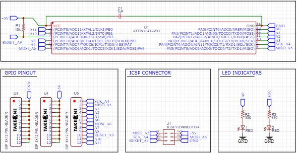
Drawing The Schematic
I put ATTINY84 with (2) led and (2) resistor, (1) capacitor with pin header
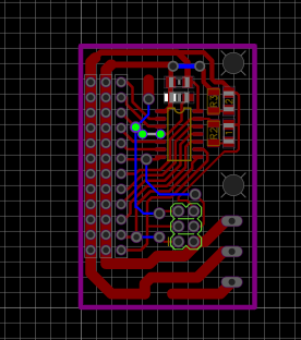
Drawing The PCB
I arranged the pieces
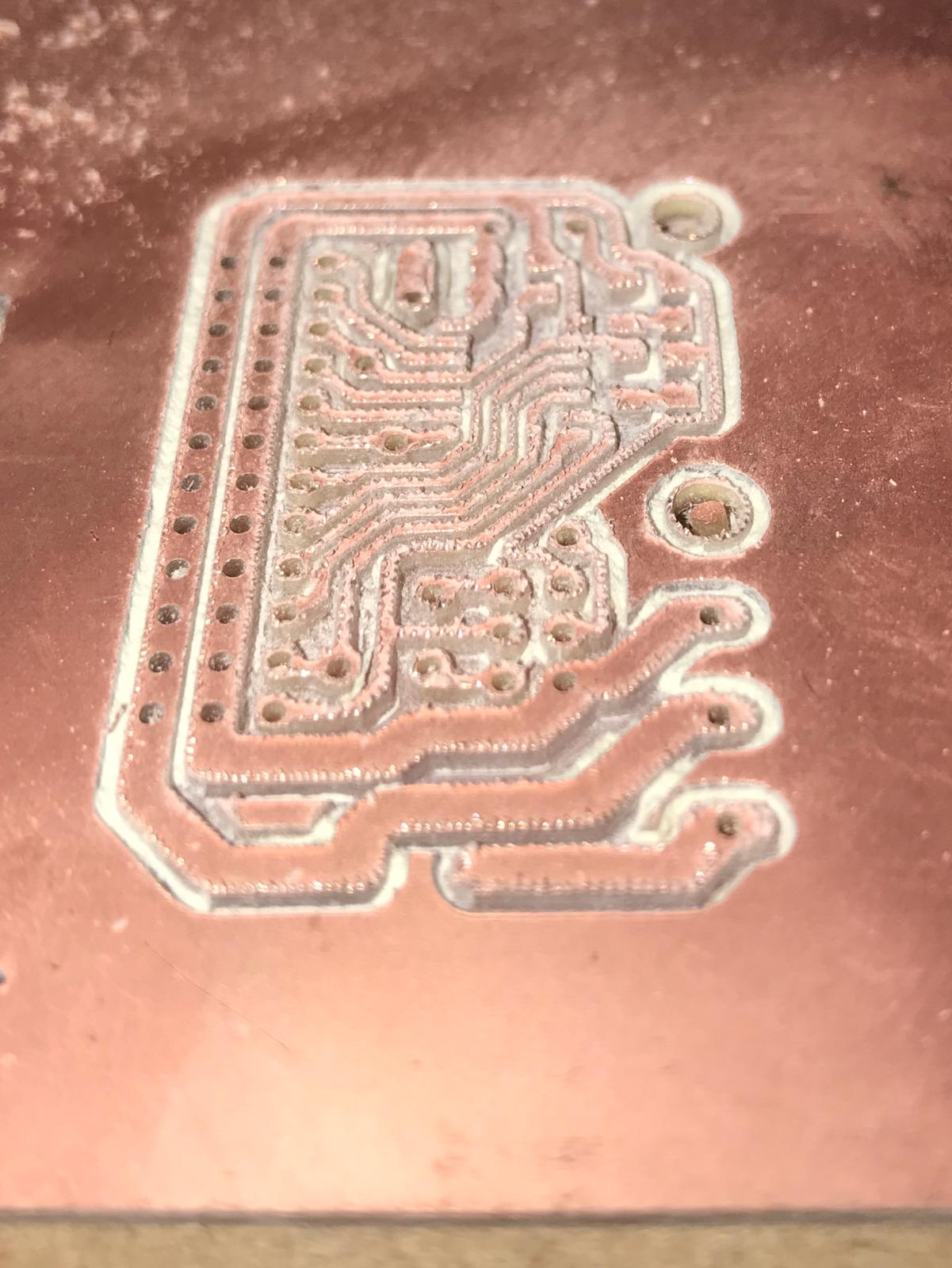
Milling & Soldering
I used a 1/64 mill bit
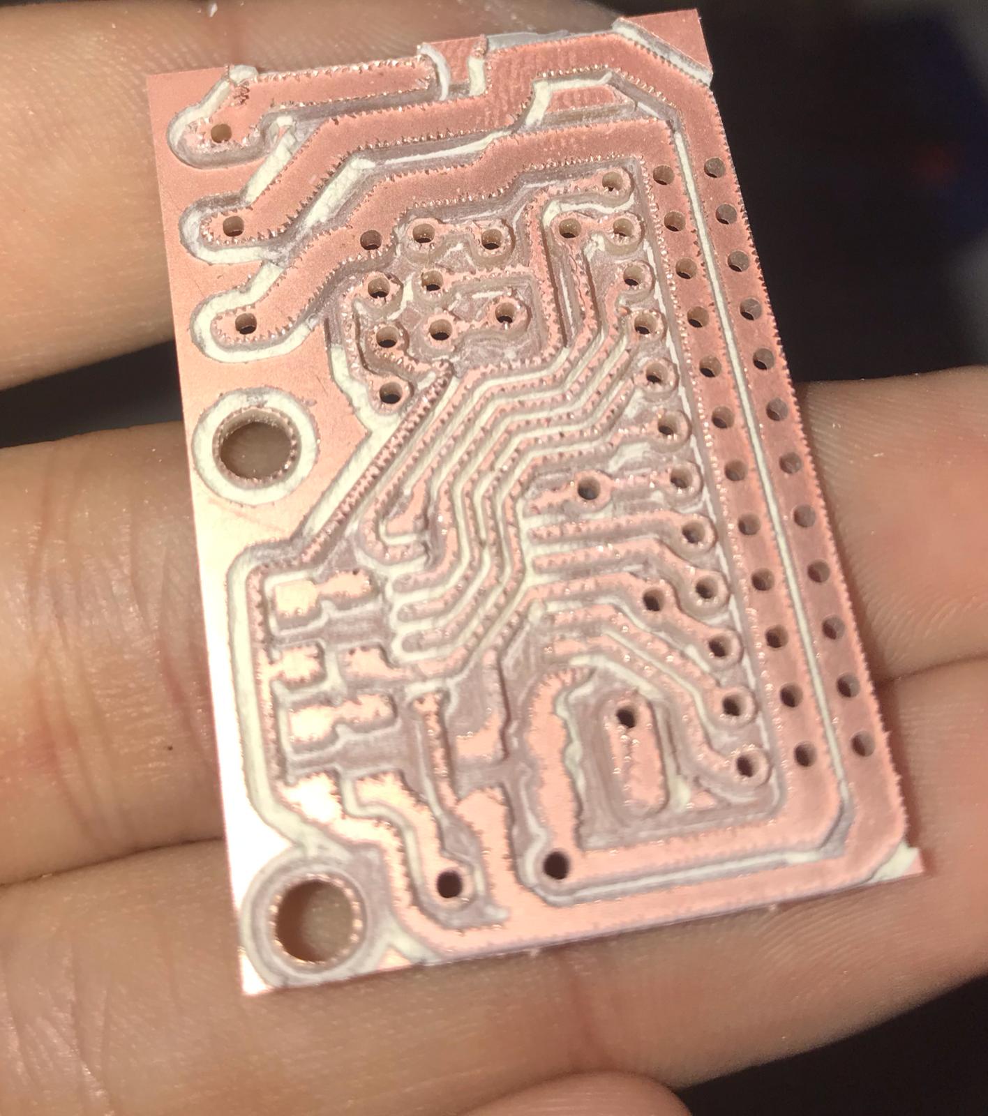
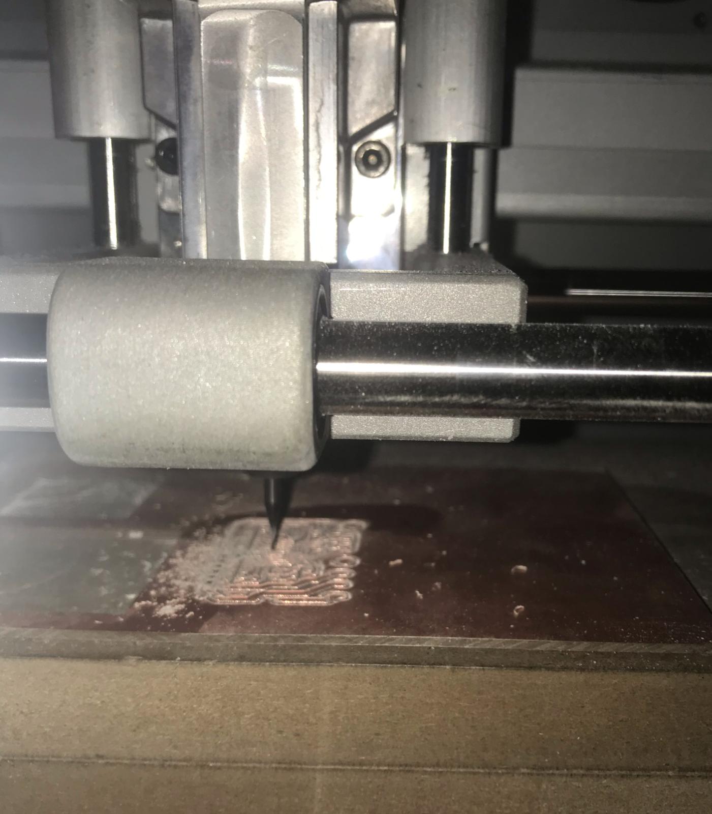 Result after digging the circuit and now I’m going to put in a 1/32 mil bit to cut out line .
After digging the circuit I cleaned the circuit from impurities
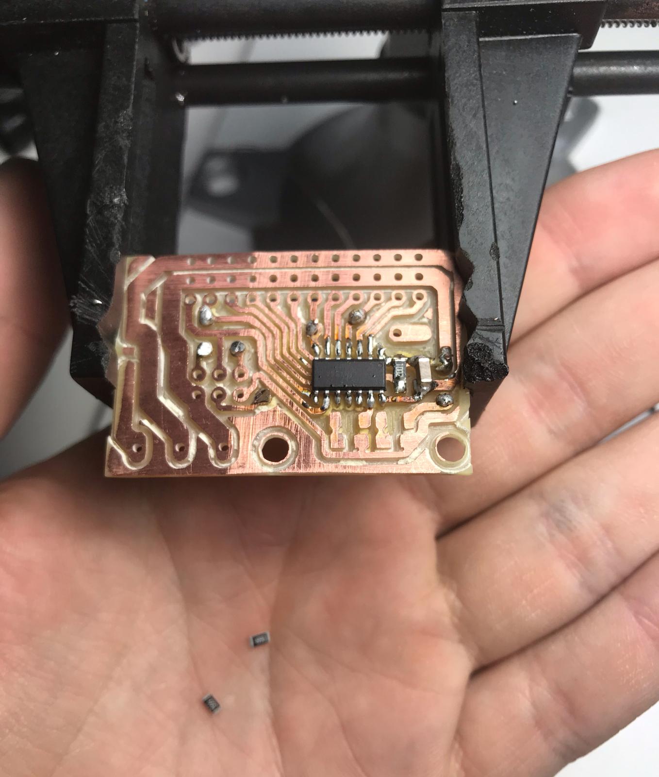
Here, I am doing a soldering for the microcontroller and the LED
- I did the same previous steps drilling the circuit and soldering the circuit
- You can check out this week to learn how you can do a Circuit Click Here
Testing my new circuit
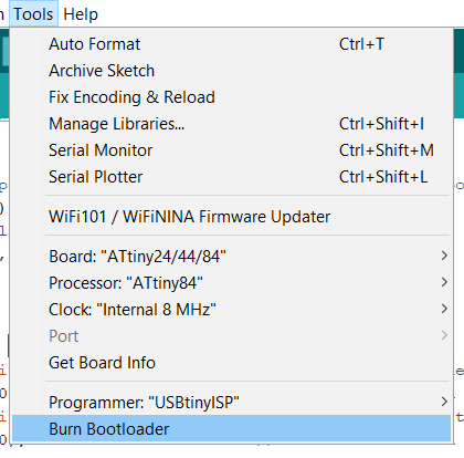
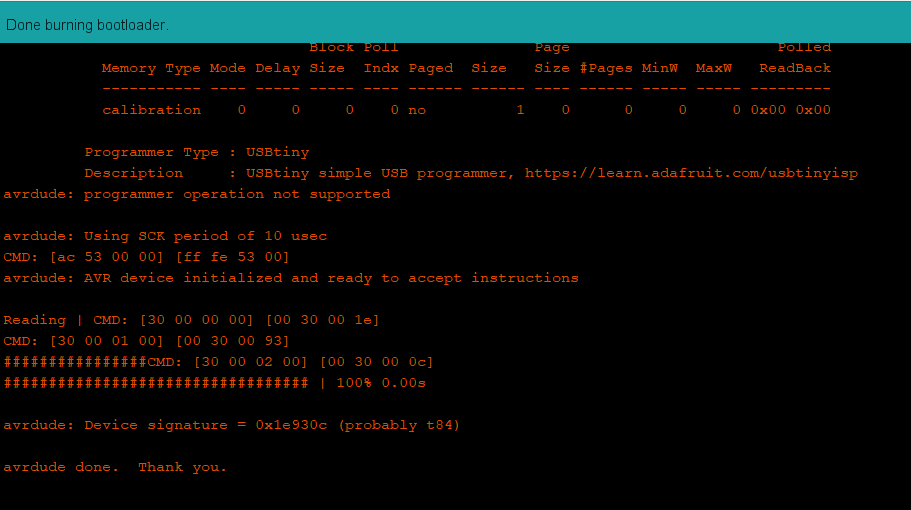
This is the result of a blink test code this means that my new board is working,I had to burn the bootloader first

Arduino IDE
- It is an electronic development board consisting of an open-source electronic circuit with a computer-controlled microcontroller and is designed to facilitate the use of interactive electronics in interdisciplinary projects. Arduino is mainly used in the design of interactive electronic projects or projects that aim to build different environmental sensors such as temperature, wind, light, pressure, etc… Arduino can be connected to different programs on the personal computer, and its programming depends on the open-source programming language, processing, and the codes are distinguished Arduino software is similar to the C language and is considered one of the easiest programming languages used in writing microcontroller programs.
Download Arduino IDE
programming Arduino UNO to be my programmer
1 I opened the Arduino program

2 I programmed my arduino so it can be my programmer

3 from the ardiuno ide examples I chose the arduino isp

4 I clicked on upload to upload the code to me “Arduino as a programmer”

5 Done uploading the code

connect programmer to my Circuit
- After making the Arduino programmer I connected to my board as this pin


Test program
1 Then to verify that the programmer is workin I programmed my Attiny using the arduino as ISP

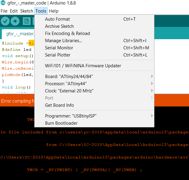
2 I went to to0ls and selected my board

3 Then I chose the blink example to try programming


blink code
/*
  Blink

  Turns an LED on for one second, then off for one second, repeatedly.

  Most Arduinos have an on-board LED you can control. On the UNO, MEGA and ZERO
  it is attached to digital pin 13, on MKR1000 on pin 6. LED_BUILTIN is set to
  the correct LED pin independent of which board is used.
  If you want to know what pin the on-board LED is connected to on your Arduino
  model, check the Technical Specs of your board at:
  https://www.arduino.cc/en/Main/Products

  modified 8 May 2014
  by Scott Fitzgerald
  modified 2 Sep 2016
  by Arturo Guadalupi
  modified 8 Sep 2016
  by Colby Newman

  This example code is in the public domain.

  http://www.arduino.cc/en/Tutorial/Blink
*/

// the setup function runs once when you press reset or power the board
void setup() {
  // initialize digital pin LED_BUILTIN as an output.
  pinMode(0, OUTPUT);
}

// the loop function runs over and over again forever
void loop() {
  digitalWrite(0, HIGH);   // turn the LED on (HIGH is the voltage level)
  delay(1000);                       // wait for a second
  digitalWrite(0, LOW);    // turn the LED off by making the voltage LOW
  delay(1000);                       // wait for a second
}
Tinkercad
- Tinkercad
- TinkerCAD is a free online service for creating basic 3D shapes and developing digital prototypes of electronic components. These prototypes include basic circuits with LED lights, buzzers, switches, and even light sensors. These prototypes can include a microprocessor as part of the design.
Tinkercad code blocks are visual blocks you can drag-and-drop to create Arduino programs. Using the Tinkercad Circuits simulator, you can test any code you create directly in the browser, before you build and program your devices with real physical components.
after I loge in website & I go to home then I press in the circuit

then create new circuit

Block Code
first I find the microcontroller that in by circuit

The code is a led and a button and when I press the button, the led works in the circuit that I made and the led that is connected to the breadboard
I started with adding if the condition so that the button can send a logic to perform some action which is turning ON an LED

- Then I added the condition that will be compared which is 1 so when the button is HIGH it will produce 1 if 1=1 the action will be performed

I created a variable called button so I can read data and save it inside it

I changed the pins numbers to the ones that I will use

I added the action which is to turn the led pin to HIGH when the button is pressed I also copied the code from the right side

I pasted the code in arduino IDE


This is the result
button code
int button = 0;

void setup()
{
  pinMode(3, INPUT);
  pinMode(4, OUTPUT);
}

void loop()
{
  button = digitalRead(3);
  if (button == 1) {
    digitalWrite(4, HIGH);
  } else {
    digitalWrite(4, LOW);
  }
  delay(10); // Delay a little bit to improve simulation performance
}