10. Input Devices
- This week I started working on the final project
group assignment page
Important note :
for this assignment I have used Arduino first , then I used my own pcd which I designed week 7 “Electronic design”

- I will use the arduino because the circuit that I made got there is a problem and does not accept programming so I used the arduino between what I go to the lab to see what the circuit problem is
Potentiometer

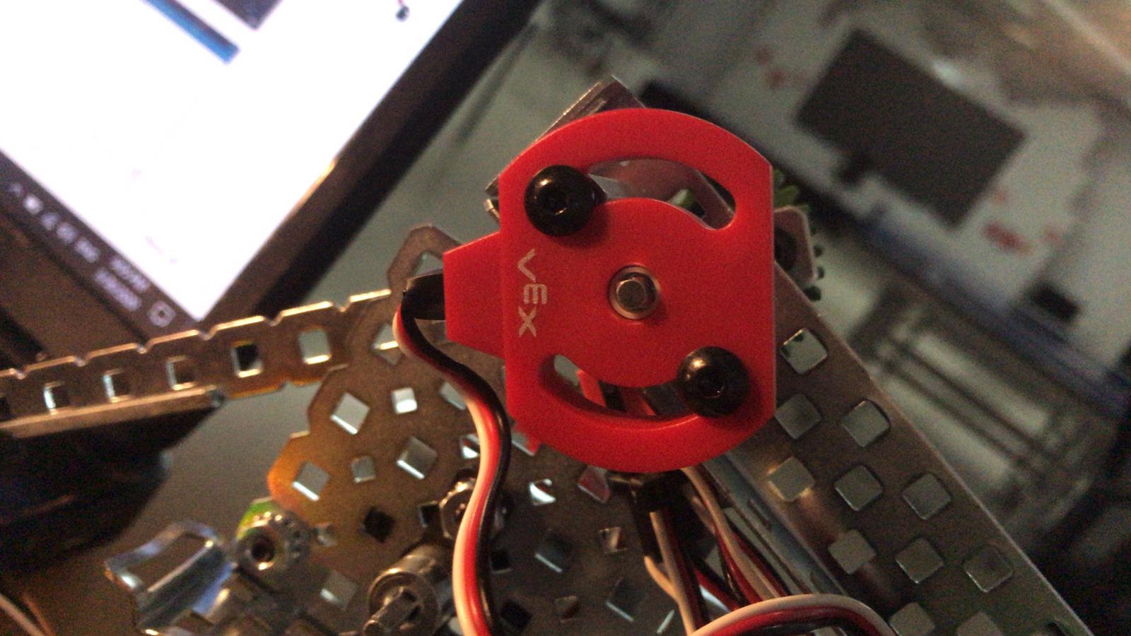
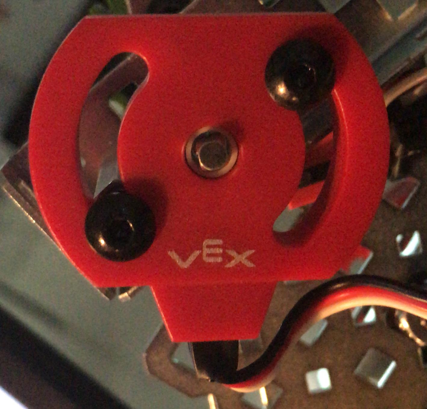
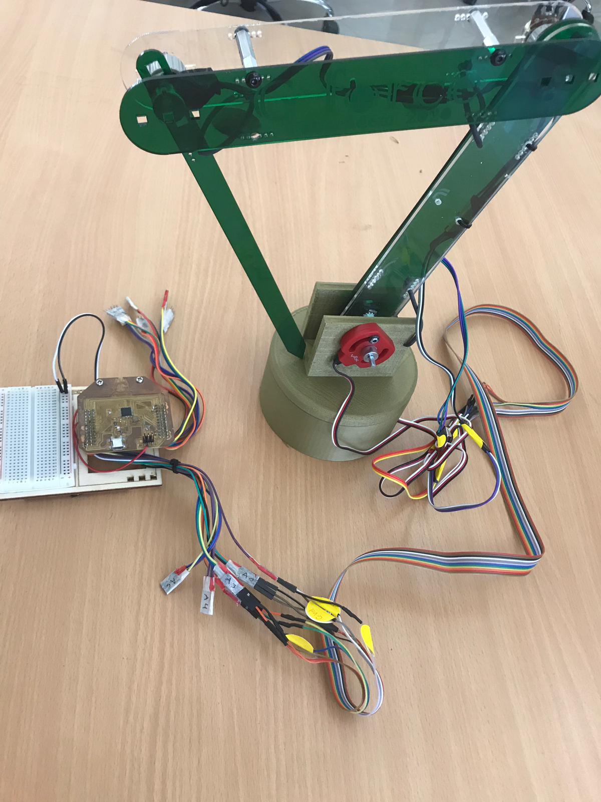
I used the potentiometer of the vex robot to mount it on the arm that would give me read and operate the servo motor.
Details
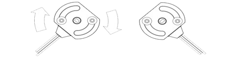

A potentiometer (or “pot”) is an electrical device used to measure angular position. The user can therefore adjust the degree to which the potentiometer opposes electric current through it, simply by turning a shaft that is attached to the center of the potentiometer. As the resistance of the potentiometer changes, so does the voltage, which thus causes the potentiometer to act as a variable voltage divider. This varying voltage can be measured by the VEX microcontroller and is directly proportional to the angular position of the shaft connected to the center of the potentiometer. This allows you to obtain an analog measurement of an angular position. The VEX potentiometer is designed with a “D-hole” in the center, which should slide easily over the VEX square shafts. The potentiometer includes two arcs, each ½in from the center hole; these arcs exist to assist with mounting the potentiometer to the robot structure.
- Benefits & Applications
Incorporating the VEX potentiometer kit into your project can make it easier for your robot to perform autonomous behaviors. A robot equipped with a potentiometer becomes aware of the position angles and motion of different components, thus making it more aware of its actions.
The VEX potentiometer can be used to measure variations in angular position of different robot components. It can be very useful when implementing robot manipulators or shooters. For example, if you are designing a shooting robot, it is possible to estimate the angle at which the robot should shoot a ball in order to get the ball into the goal from a known distance.
- Range Limits
The mounting arcs allow for up 90º of adjustment to the potentiometer’s position. Since the potentiometer has limited angular travel, it is important to ensure that the shaft that is being measured by the potentiometer does not travel more than 260º (the potentiometer can only move approximately 265º ±5º and can only electrically measure 250º ±20º). The adjustment arcs allow the potentiometer’s range of motion to be repositioned to match the shaft’s range of motion.
To measure the motion of something that rotates more than 230º, try gearing down the shaft’s motion such that the gear attached to this “primary” shaft turns a larger gear attached to a “secondary” shaft. This secondary shaft will therefore rotate less distance than the primary shaft. Once the gear sizes are adjusted such that the range of motion of the secondary shaft is within that of the potentiometer, attach the secondary shaft to the potentiometer. This way, you should be able to indirectly measure the rotation of the primary shaft by directly measuring the rotation of the secondary shaft.
i took these infromation from
-
In the (9) week I explained about Arduino and how to deal with Arduino
-
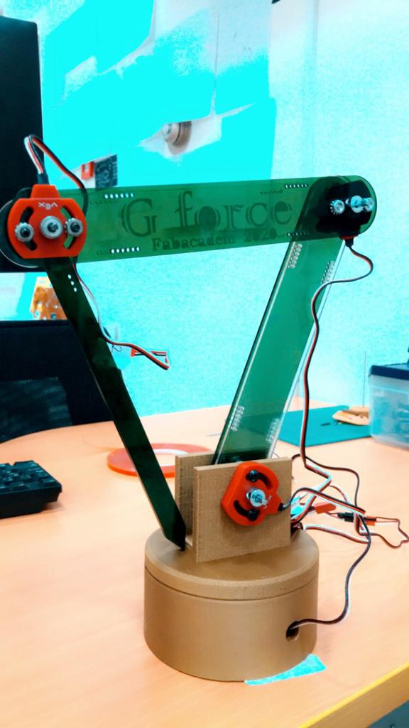
I used the VEX robot pieces to make the prototype of the final Fab Academy project, which is the rolling ribs that do not control motor death and others. It scans the codes and converts them to an image
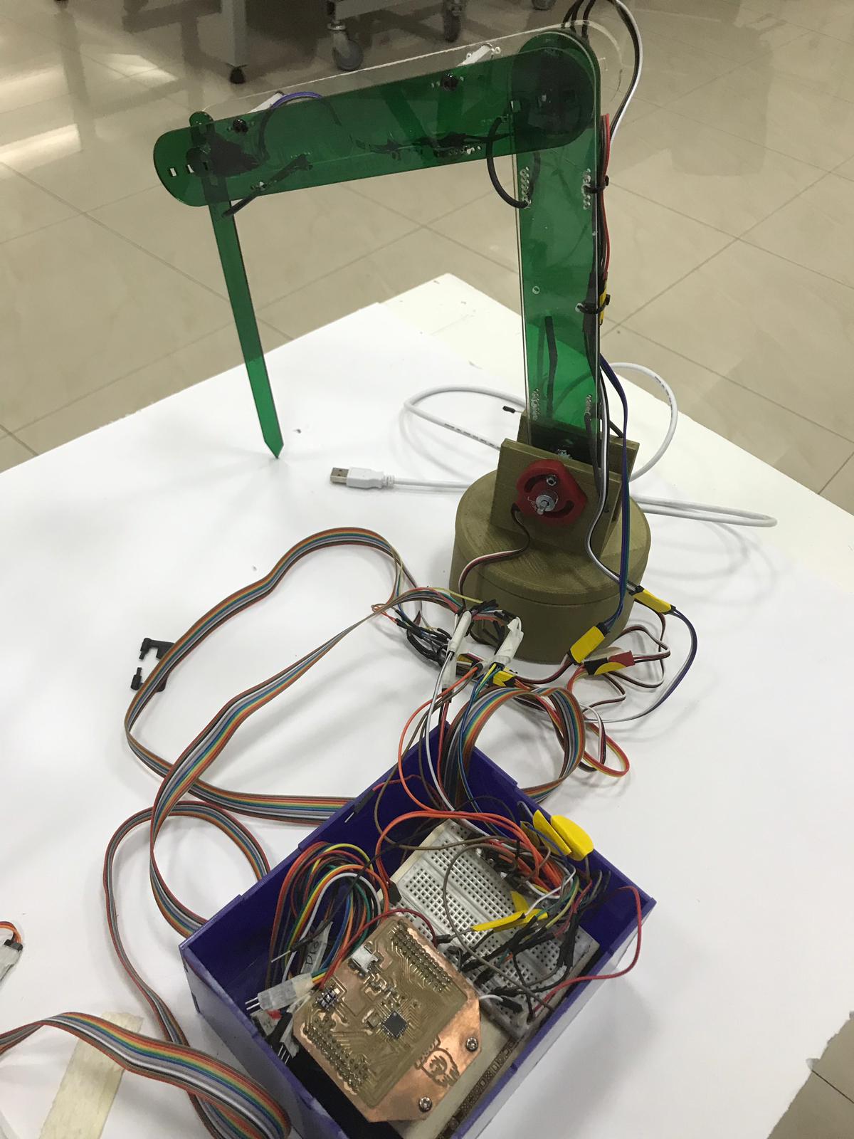
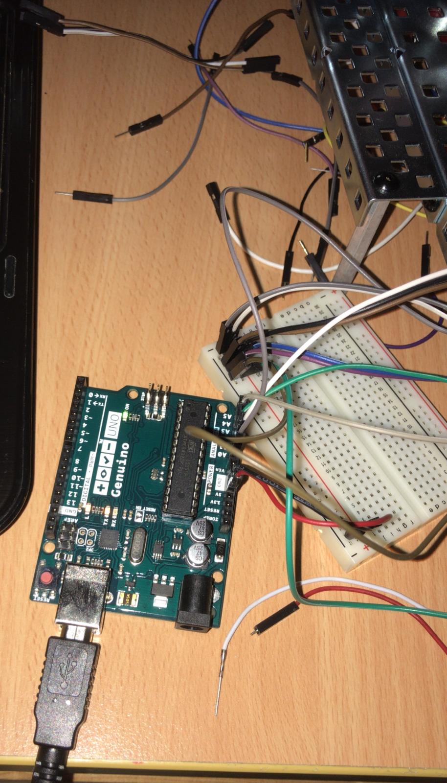
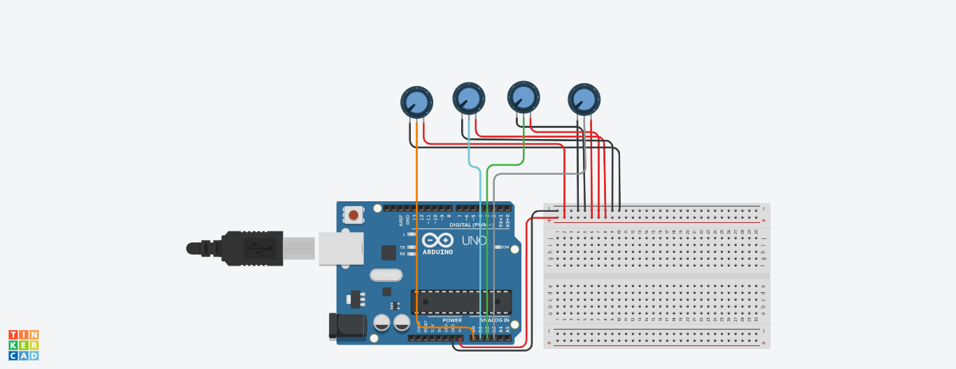
Connections
- Variable resistance robot (VEX) was used from 0 to 180 degrees
- Use 4 variable resistors to have the smooth and desired movement
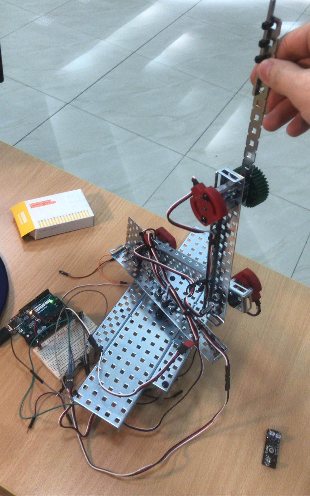
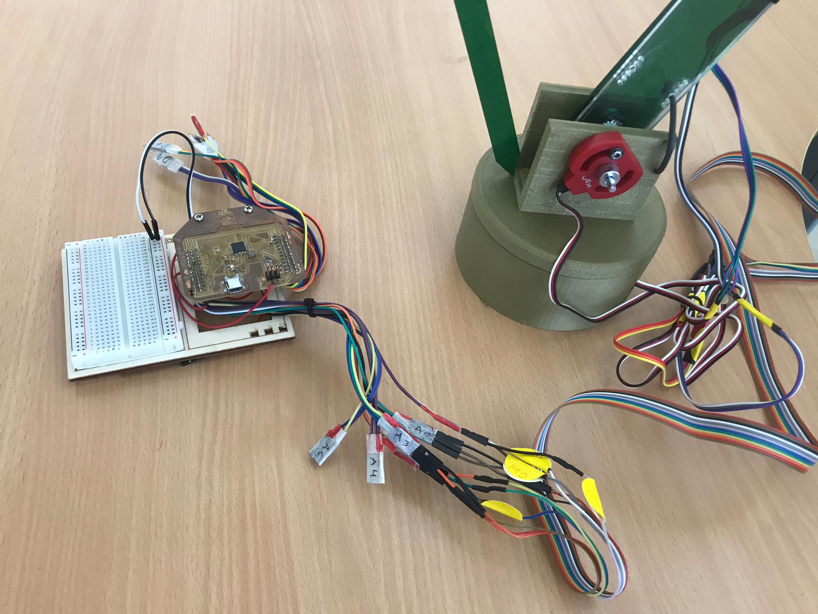
- I connected the wires to the Arduino to program them
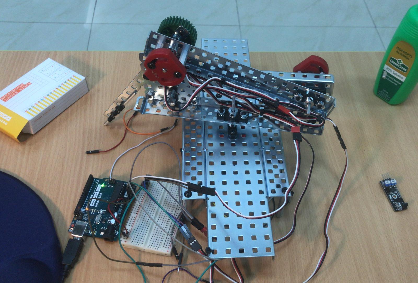
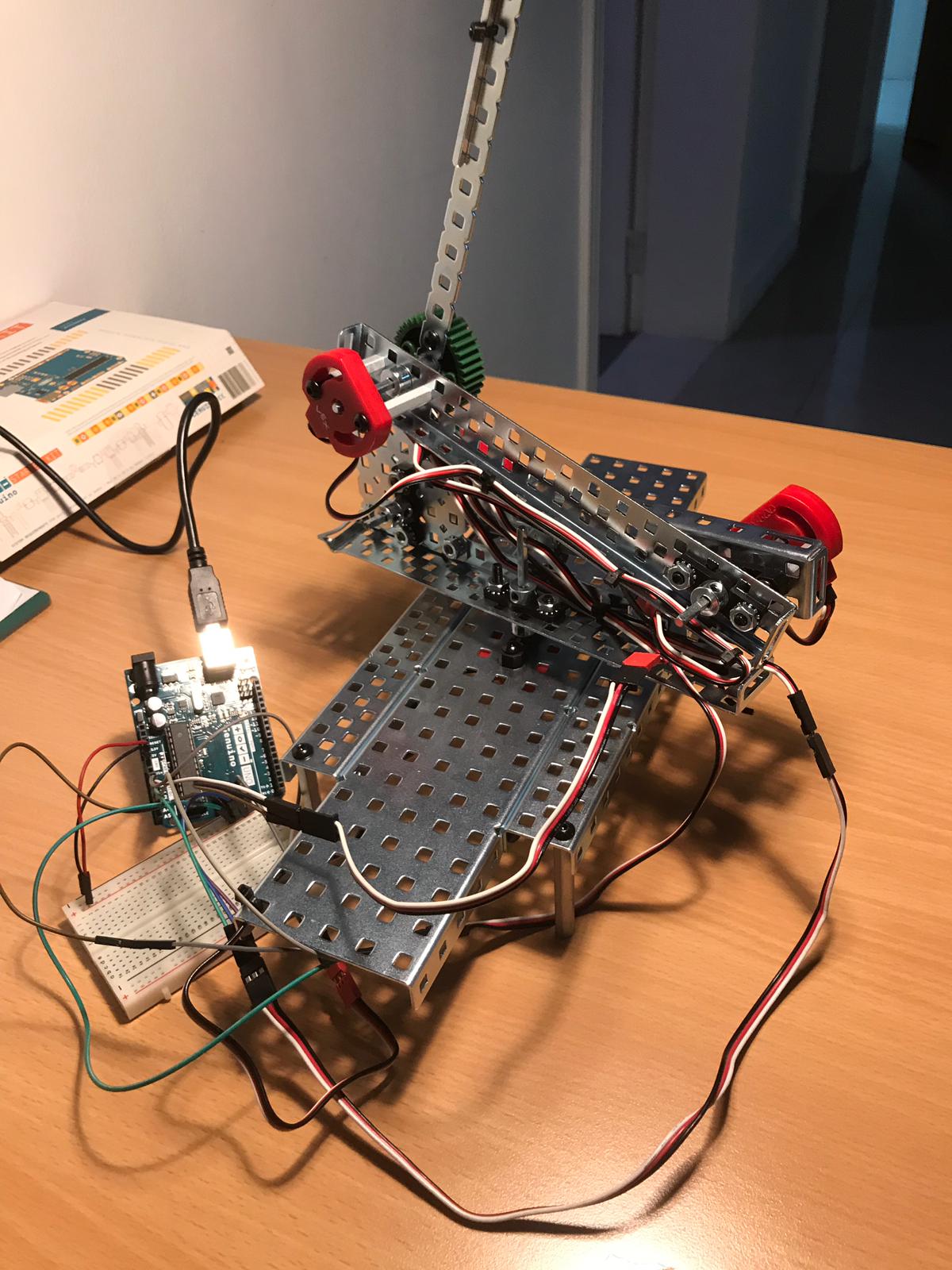
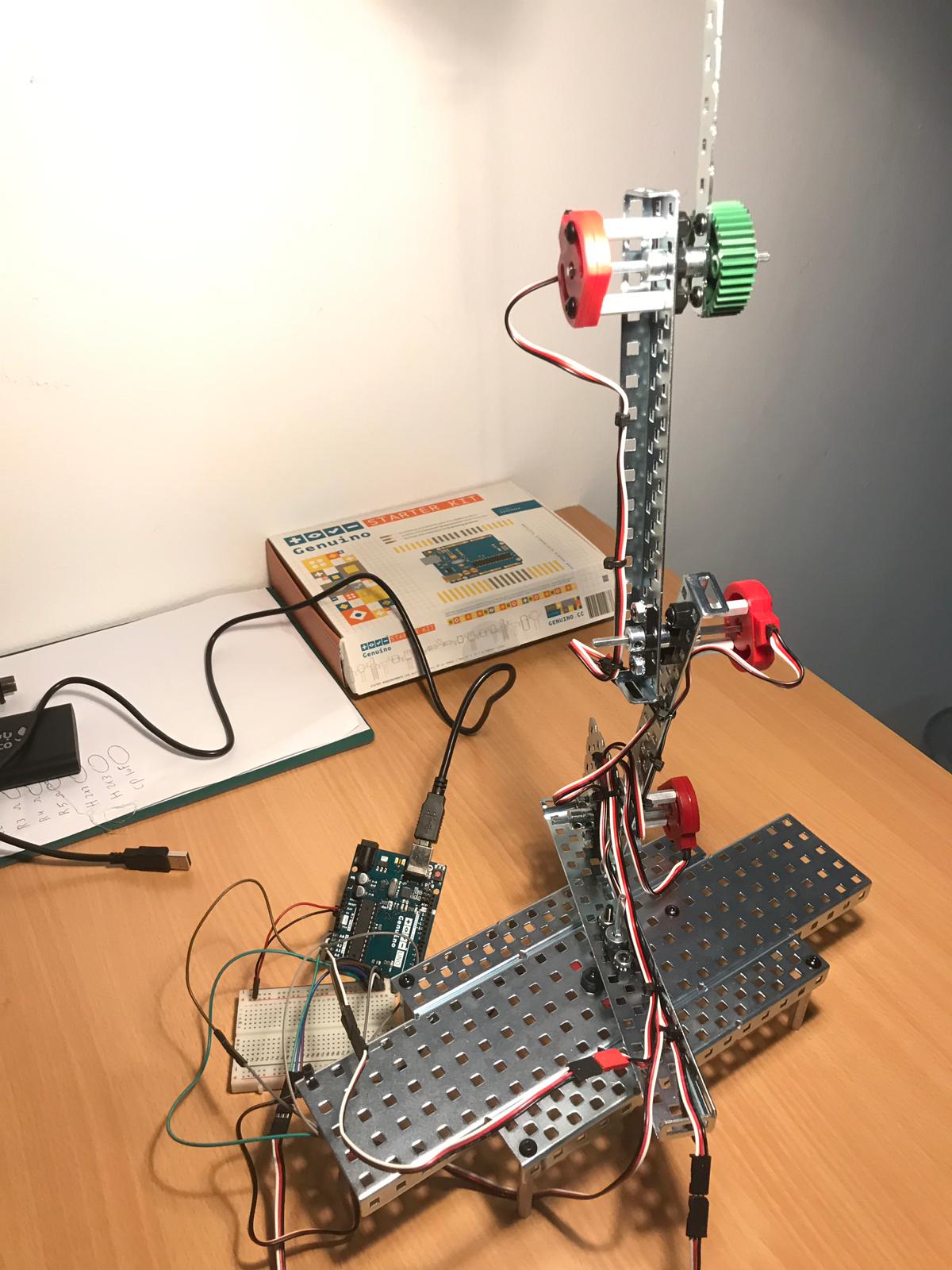
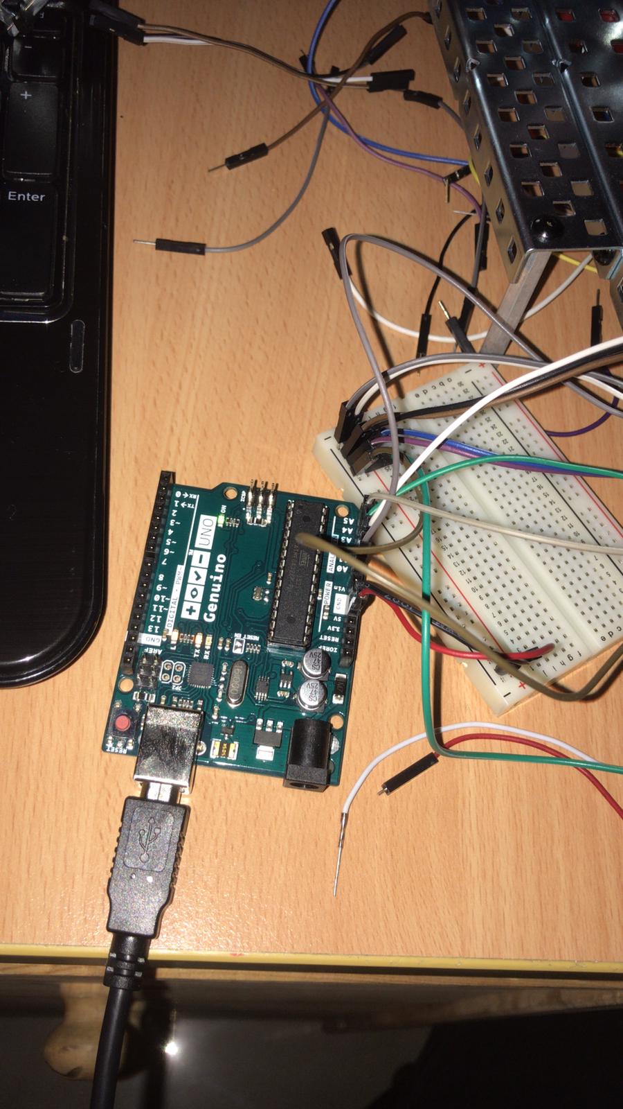
- After connecting the wires, I connected the Arduino to the computer to start programming the sensors
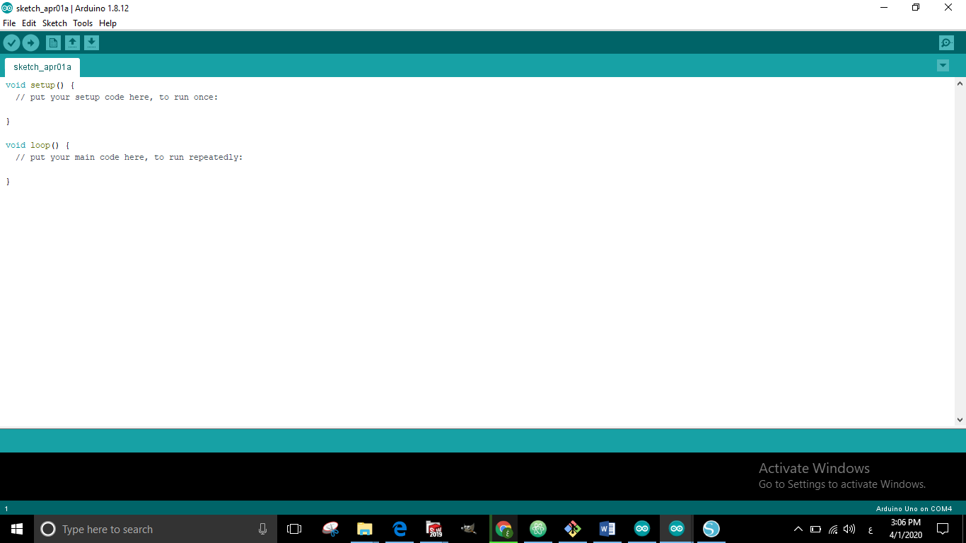
Programming
- I opened the Arduino program
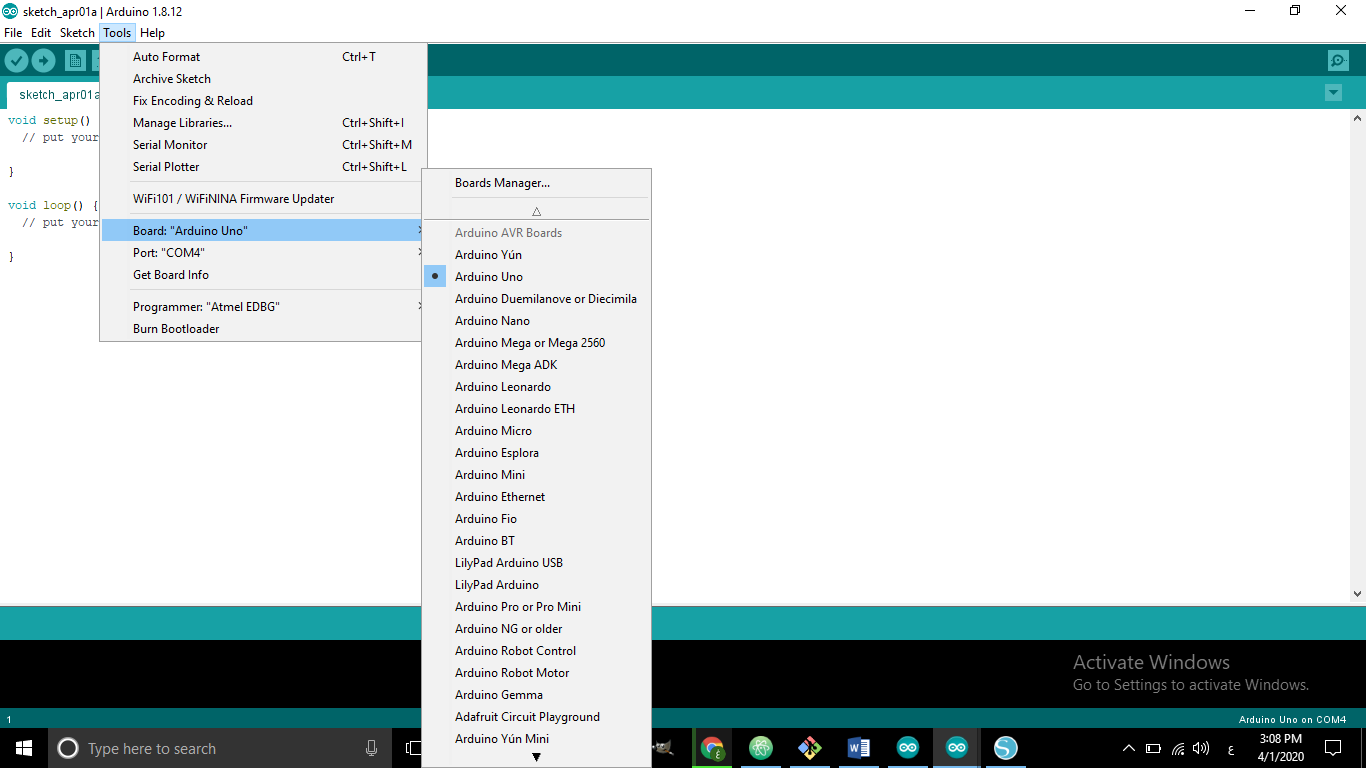
- I chose Arduino which I will program, which is Arduino Uno
- Then I chose the port
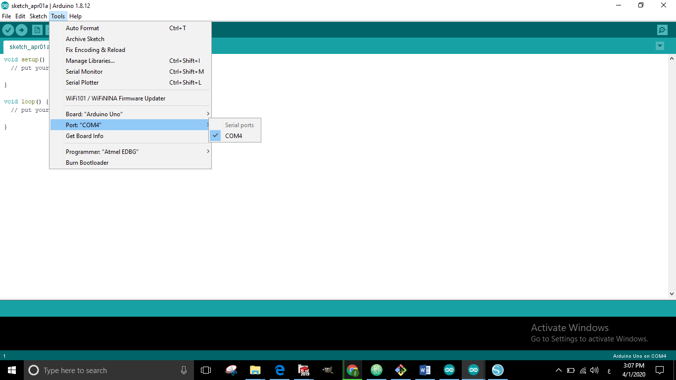
- I wrote the code with a choice of ports that I would like to use
Note
After I tested the pinchometer with the Arduino, I connected all the connections to the board that I designed
schematic
Component list
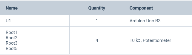
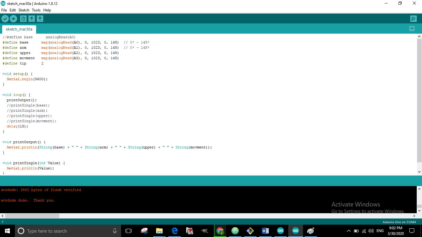
Programming code
#define base      analogRead(A0)
#define arm       analogRead(A1)
#define upper     analogRead(A2)
#define movment   analogRead(A3)
#define tip       2

void setup() {
  Serial.begin(9600);
}

void loop() {
  printOutput();
  //printSingle(base);
  //printSingle(arm);
  //printSingle(upper);
  //printSingle(movment);
  delay(15);
}

void printOutput() {
  Serial.println(String(base) + " " + String(arm) + " " + String(upper) + " " + String(movment));
}

void printSingle(int Value) {
  Serial.println(Value);
}
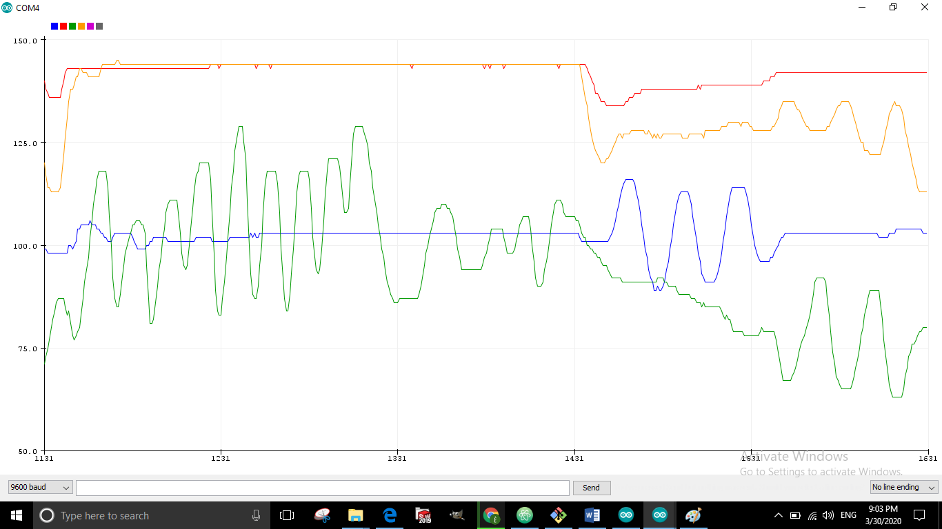
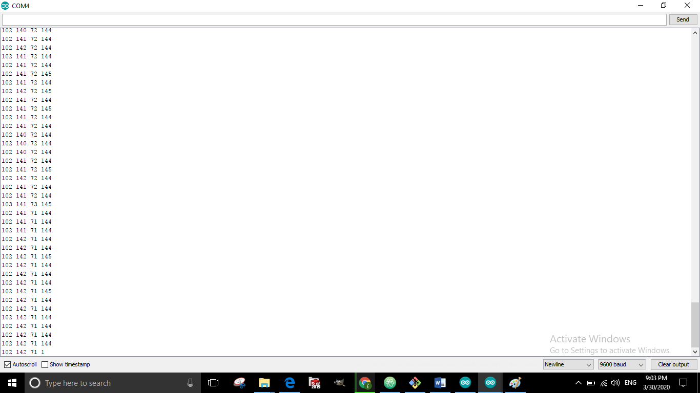
Readings
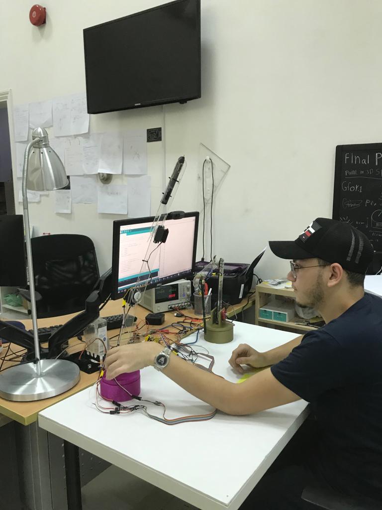
- In this video, I was experimenting with entering the readings from the circuit that i designed and taking them out to the other arm. There were some errors in the numbers and the readings, but I modified them by some correction factors
- serial monitor
- serial potter