Week 11. INPUT devices
The main objectives were to measure something by adding a sensor to a microcontroller board. As the group work probe an input device's analog levels and digital signals.
Individual work:
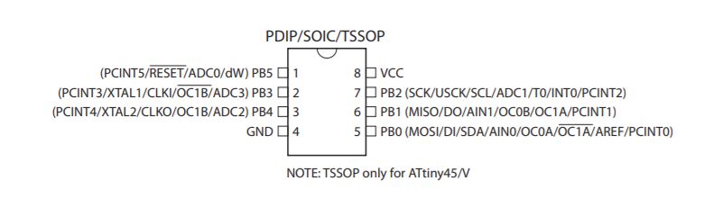
For the individual assignment, I decided to use Neil's design for the light sensor. When I checked the previous year students' documents I found out that Behnaz has done something similar to the what I planned to do. After checking her documentation I got an idea what exactly I should do when designing the board. To begin with,I started with having a look at the pin configuration for ATtiny 45.
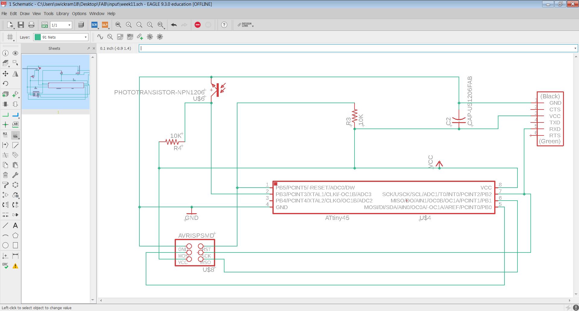
After that, I designed the schematic on Eagle keeping Neil's design as the reference.
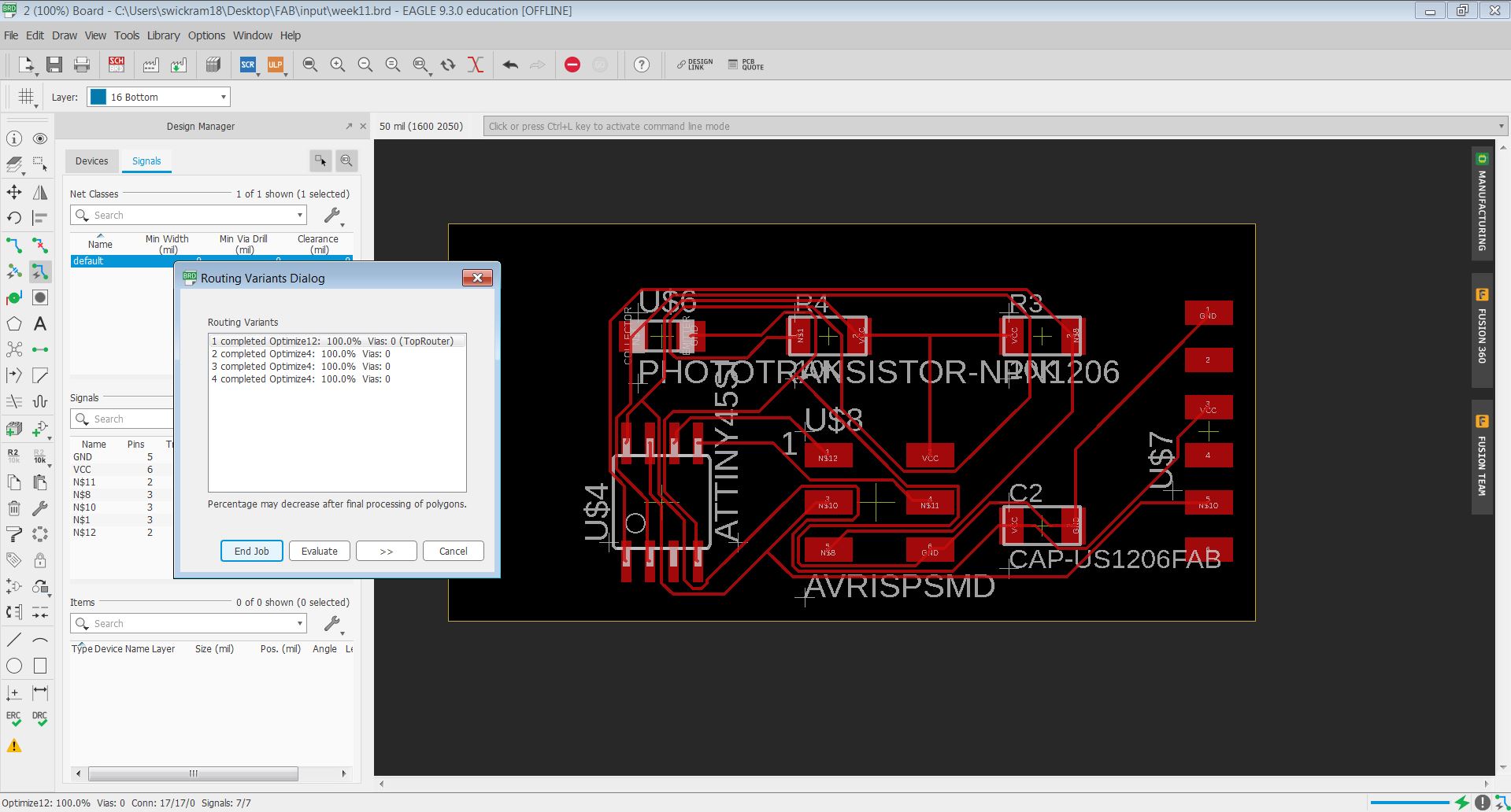
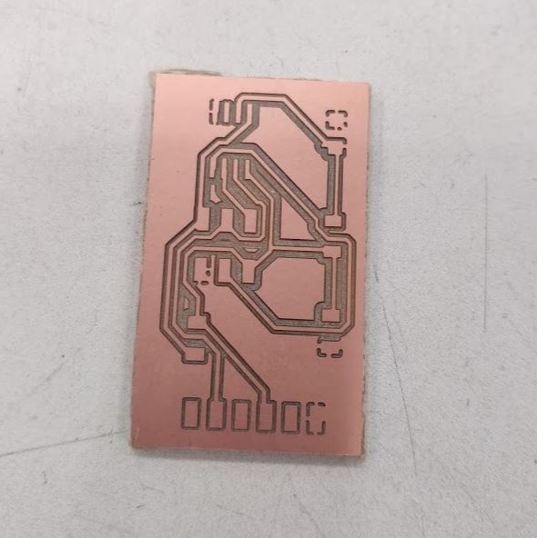
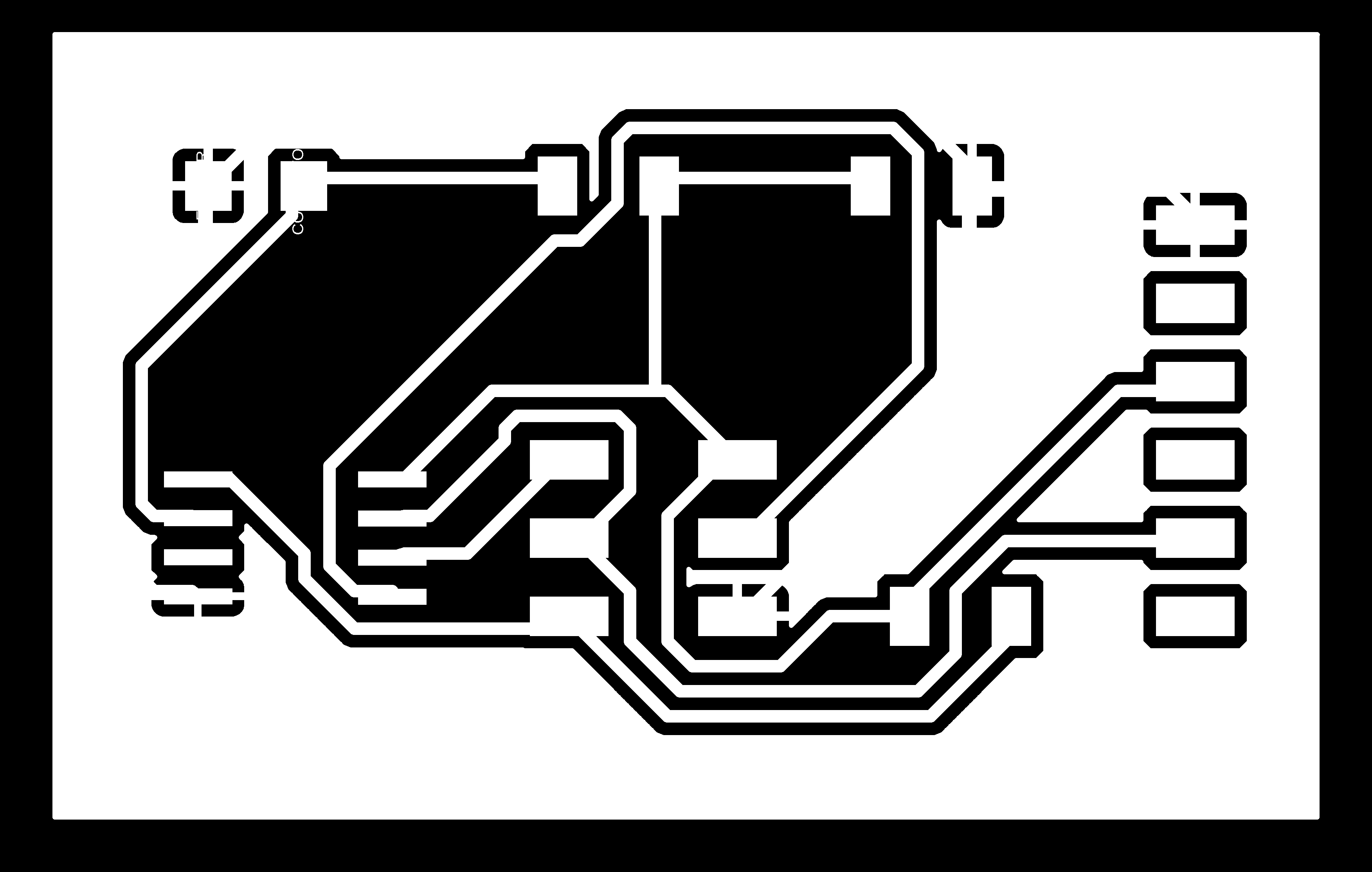
Next, I designed the layout based on the schematic design. The Auto-routing feature worked, in this case, due to the smaller number of components. I used "Rip up; rats nest; AutoRouter;" for replacing the components and optimizing the nets and finally succeeded.
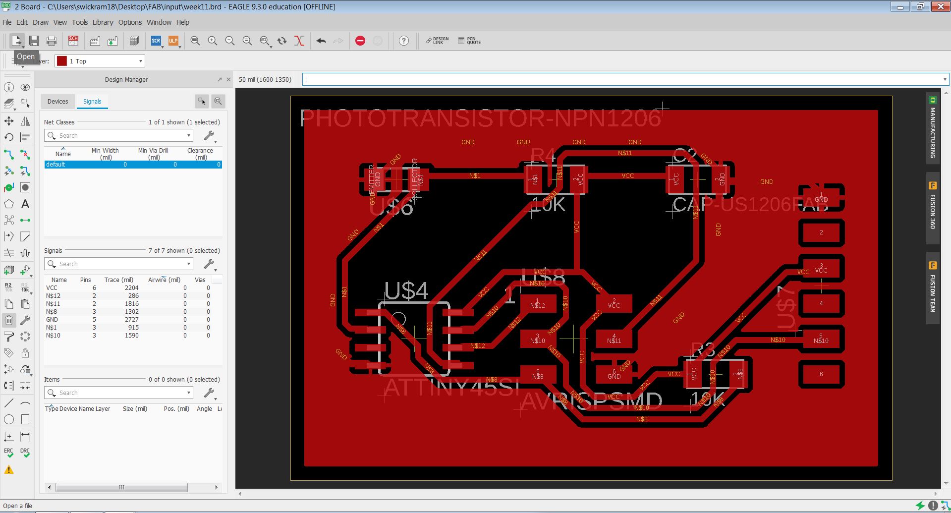
Preparations for exporting the traces and outlines as well as the process of milling and soldering were explained the process in detail in Electronics Design week.
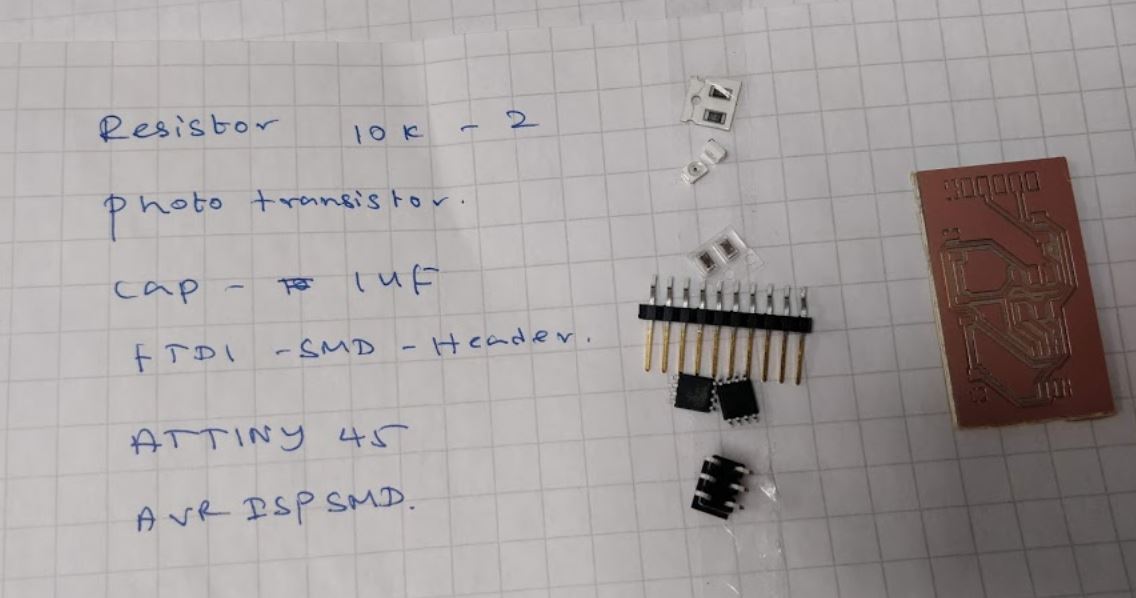
The list of components for soldering:
- 2x Resistor 10K
- Phototransistor
- Capacitor 1UF
- FTDI SMD Header (fab)
- ATtiny 45
- AVRISPSMD
Programming the Board
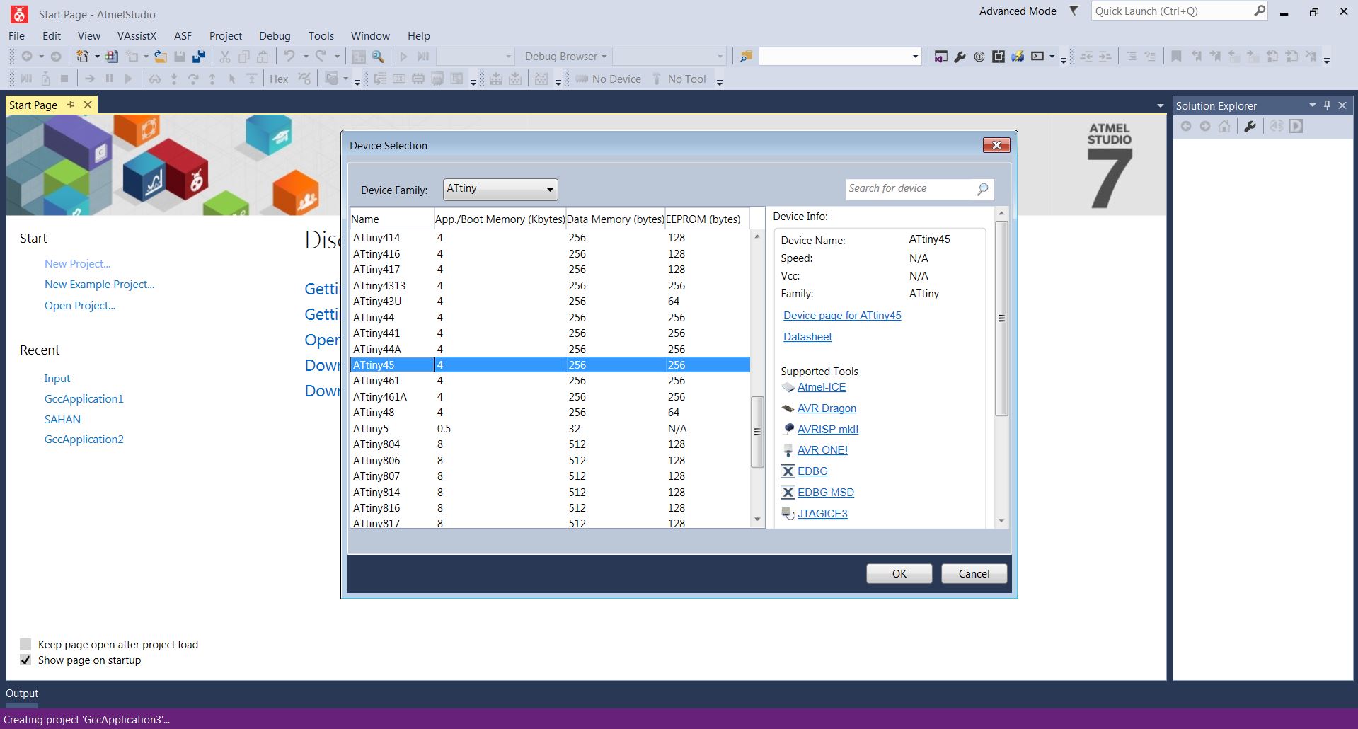
I used the Atmel studio to program the board. First I opened the Atmel studio (run as administrator) > create new project > selecting ATtiny 45.
Then I copied Neil's code for hello.light.45.c Then I defined that clock speed on the code as
#define F_CPU 8000000UL
The details about the internal clock were found on on the datasheet. Here the datasheet was helpful for me to program the board.
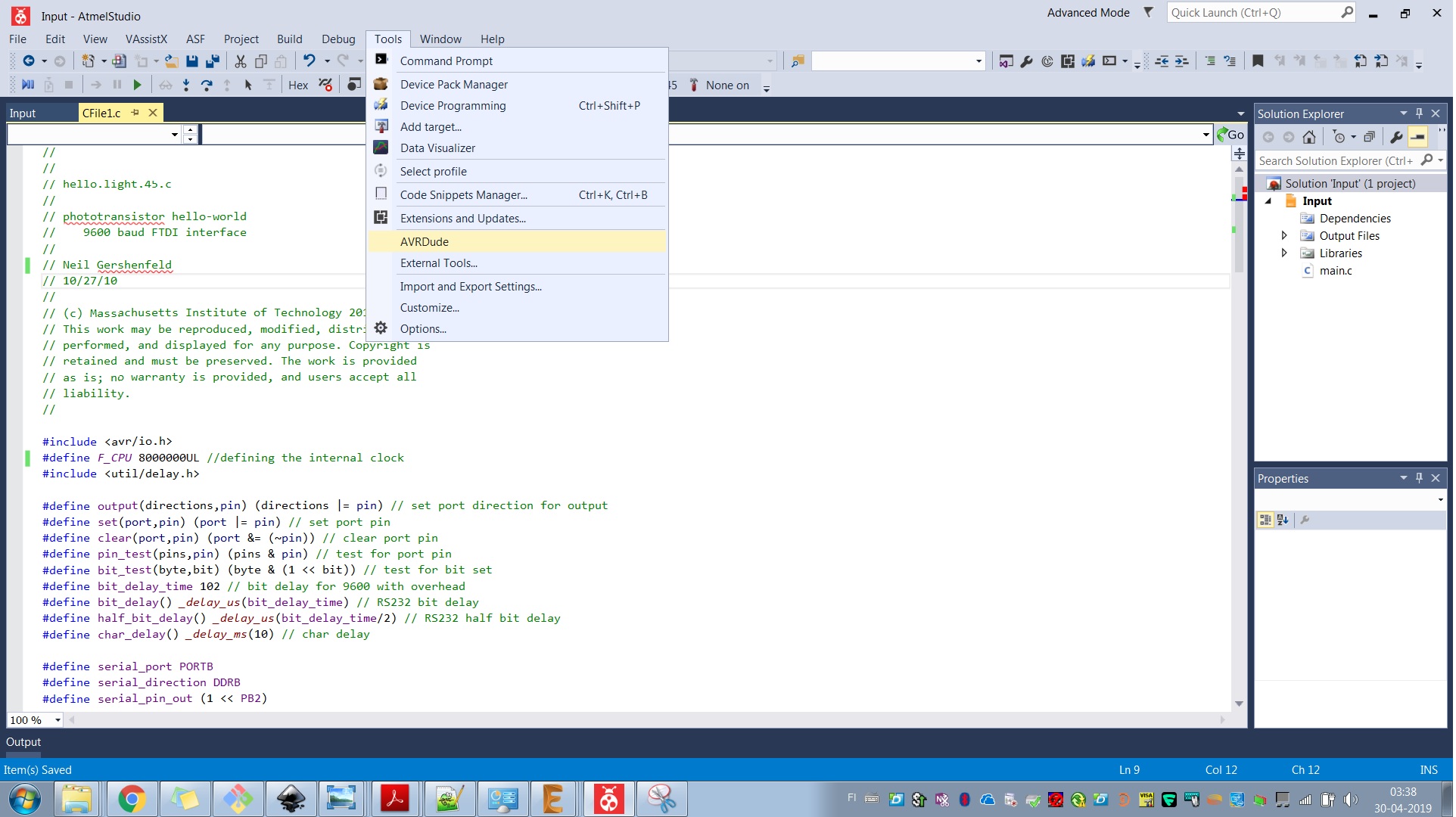
In the external tools, I needed to add the Avrdude. For that, I used the following procedure.
Tools > External Tools:
- Title: AVRDUDE
- Command: C:\Program Files (x86)\avrdude\avrdude.exe
- Arguments: -p t45 usb -c usbtiny -U flash:w:$(TargetDir)$(TargetName).hex:i
- Initial Directory: C:\Program Files (x86)\avrdude\
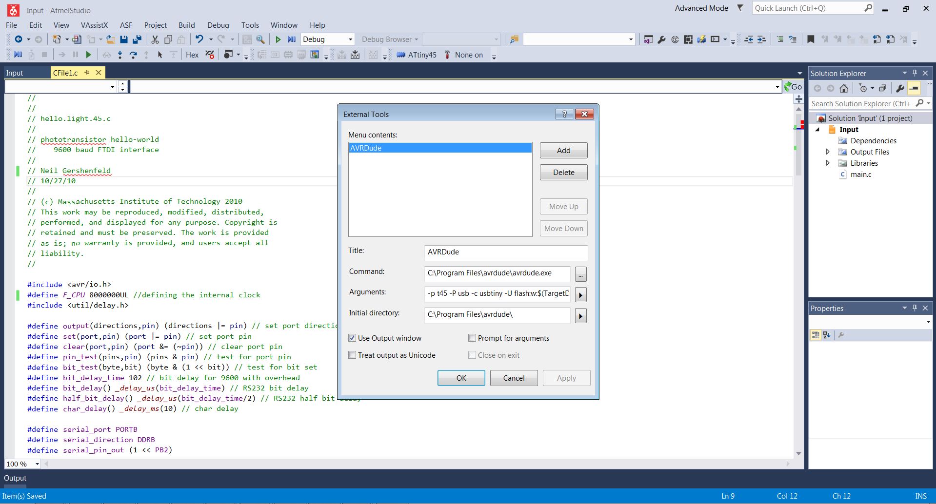
And then it can be seen that AVRDUDE is added under the tool tab.
After connecting the board and programmer and computer (using FTDI cable and programming cable) Then in Atmel Studio: Build > Compile
For testing the sensor I installed Python first. I installed the 'Python 2.7.14' version. Then after opening the command line on the location that 'hello.light.45.py' is saved and typed 'hello.light.45.py com3'. Here my COM port was 3. After that the working of the light sensor was succesfully illustrated.
When talking about the issues I faced, I was not able to program the board because of the AVRdude was not opened when run the code. I fixed this issue by correctly adding the path of avedude to the external tools arguments as explained earlier.
Group work:
For the group assignment, I worked with Alok, Jobin, Michael, and Yasir to probe a hall sensor’s analog and digital signals.
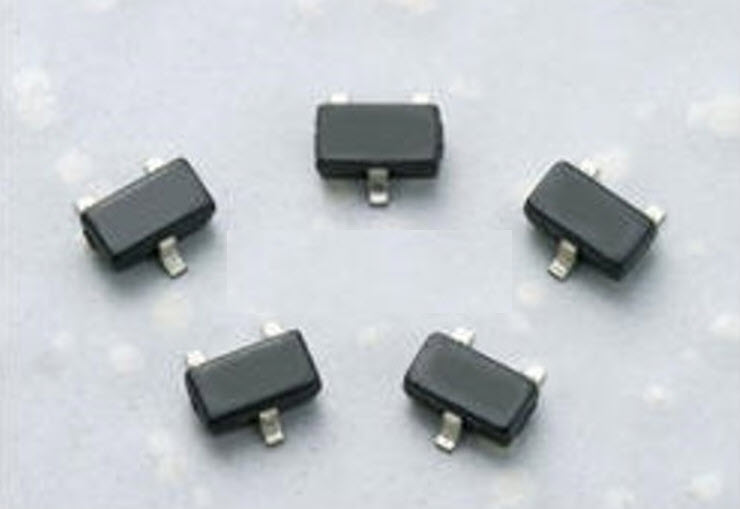
A Hall effect sensor is a device that is used to measure the magnitude of a magnetic field. Its output voltage is directly proportional to the magnetic field strength through it. Hall Effect sensors are used for proximity sensing, positioning, speed detection, and current sensing applications. The Hall Effect sensor that we used was A3245: Chopper-Stabilized Omnipolar Hall-Effect Switch. The A3245 integrated circuit is an omnipolar, ultrasensitive Hall-effect switch with a digital output. This device has an integrated regulator permitting operation to 24 V, making it the first omnipolar switch available for operation to 24 V. This device is especially suited for operation over extended temperature ranges, up to +150°C.
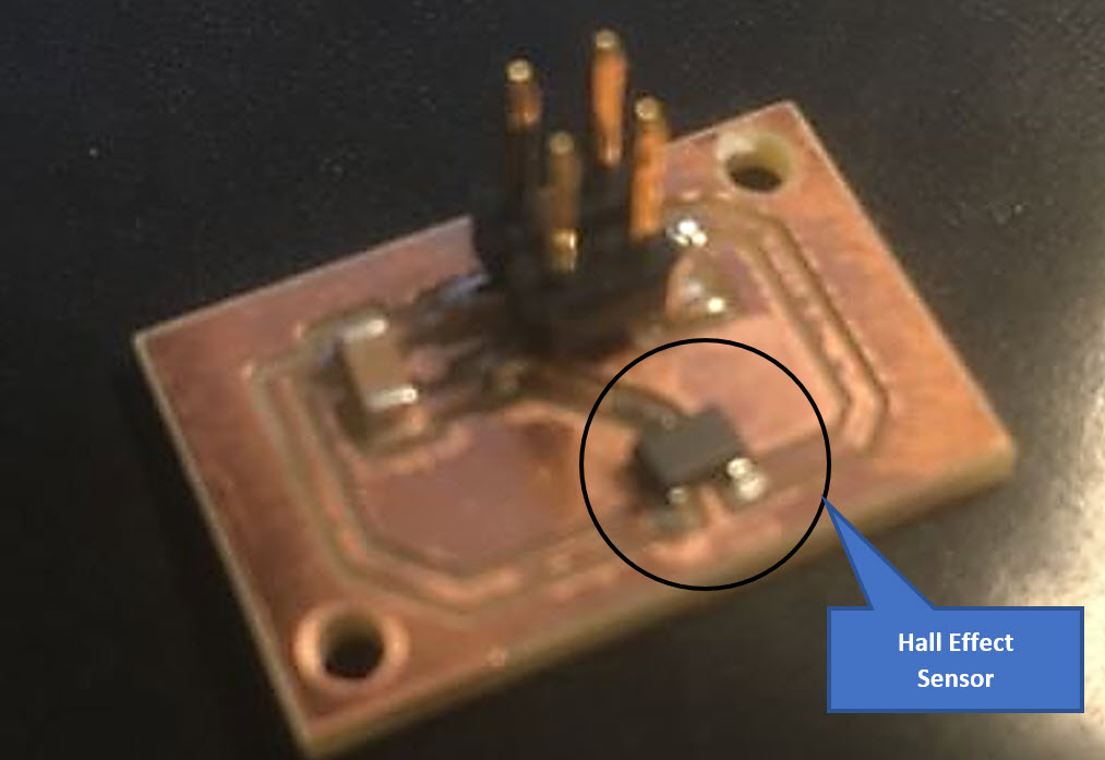
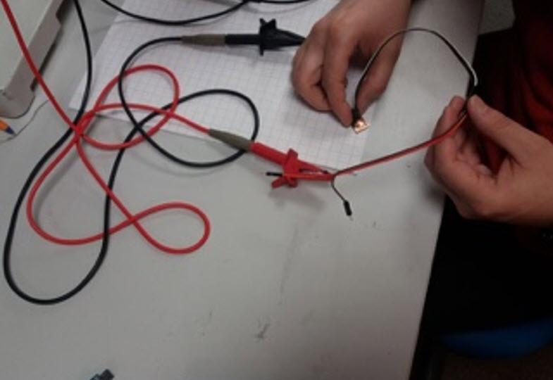
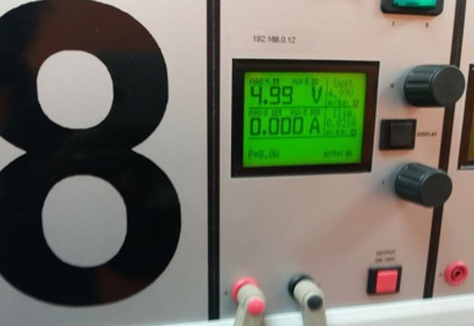
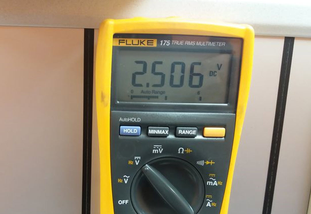
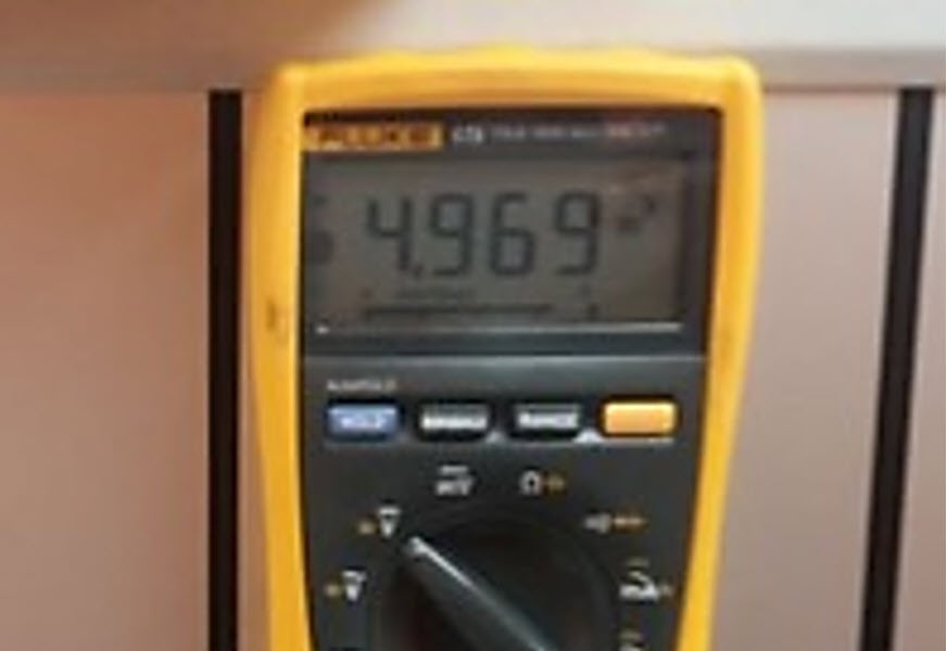
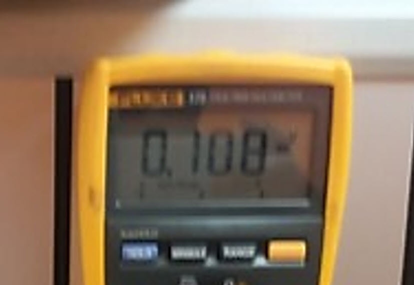
The sensor board was tested by applying 5V power supply across it and measured the resulting voltage at the output of the sensor. The output voltage with no magnetic field nearby was 2.5V. When the flip side of the magnet was brought close to the sensor, it gave an output voltage of 5V and when the south pole of the magnet was brought close to the sensor, it gave an output voltage of 0V, This clearly Indicated that the sensor was working perfectly.
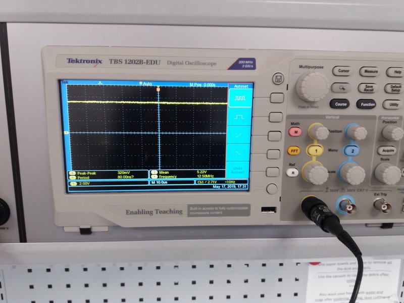
We also measured the digital signal with an oscilloscope by attaching the ground pin to the PCB ground and the positive probe to the transmit/receive pins of the ATtiny44.
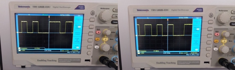
When the the flip side of the magnet came close to the sensor, we got following signal from oscilloscope.
When the magnet was close to the sensor, we got the following signals.
Therefore in conclusion we got an idea about the analog to digital conversion.
Models files
Outline for the trace
Eagle layout file
Eagle schematic design file
atmel studio file
python code to display the light sensor data