Week 12.OUTPUT DEVICES
Objectives of this week to add an output device to a microcontroller board you've designed, and program it to do something. As the group assignment to measure the power consumption of an output device.
Individual work:
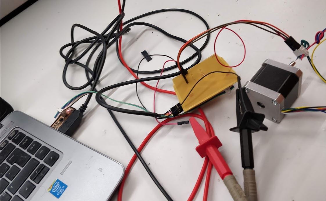
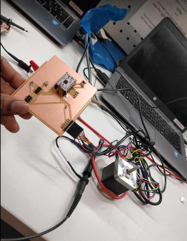
I decided to use the stepper motor as the output device since I was going to use it for my final project. First I needed to get familiar with the concept of the stepper motor. Therefore I referred to some online material regarding the stepper motors.
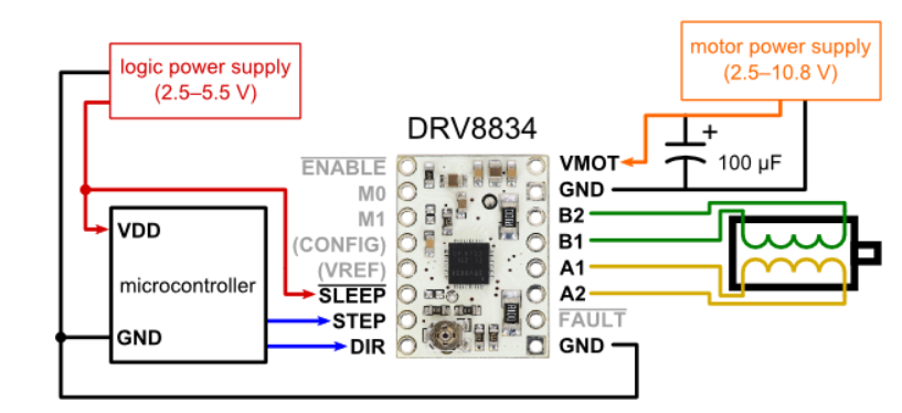
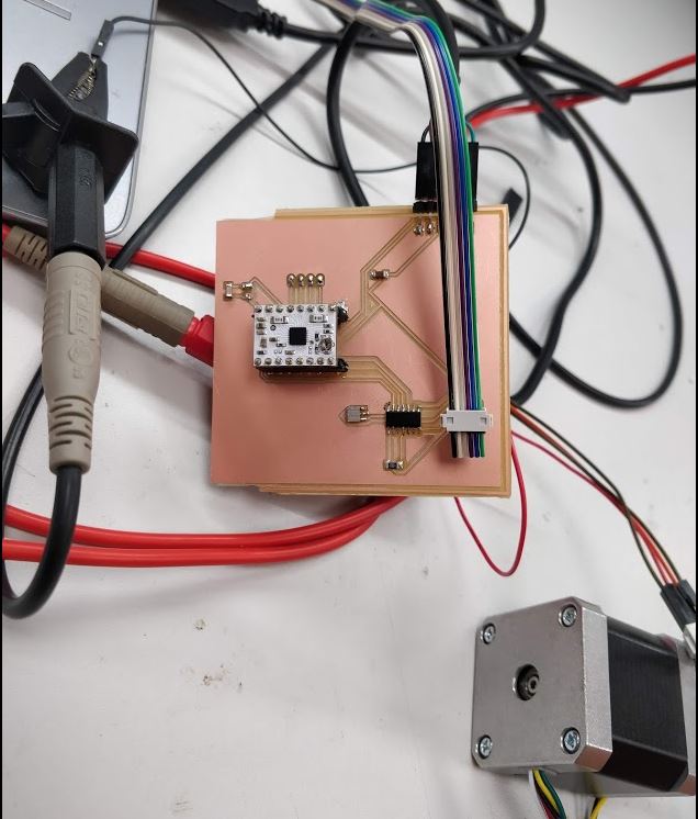
The Stepper driver I used is DRV8834 Low-Voltage Stepper Motor Driver Carrier. I read the data sheet for the driver and got an idea of how to make it attached to my design.
The designed my board based on the information from Pololu website.
After that, I modified my microcontroller from embedded programming week to work with the stepper motor. Here I added rails to mount the stepper controller, get output from it and to give input voltage into the circuit.
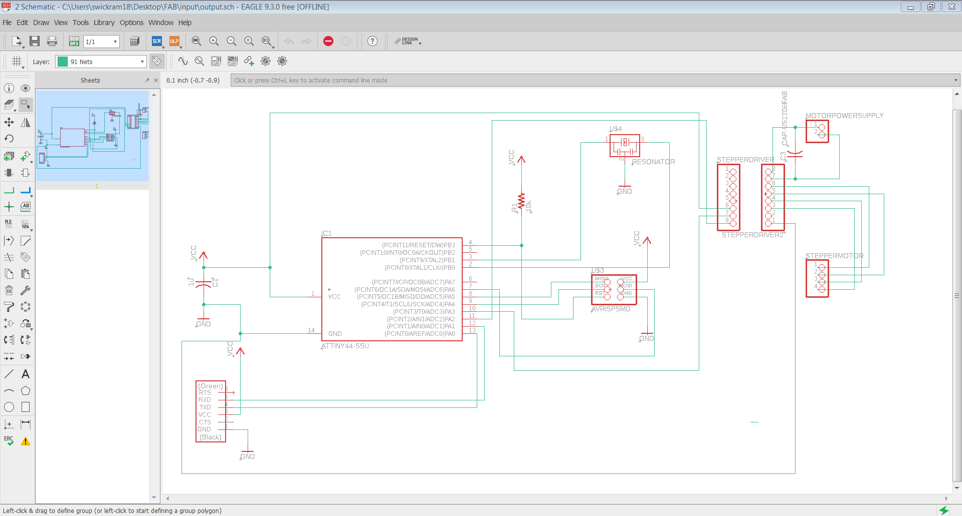
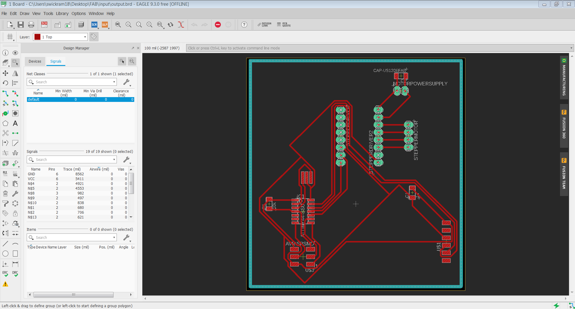
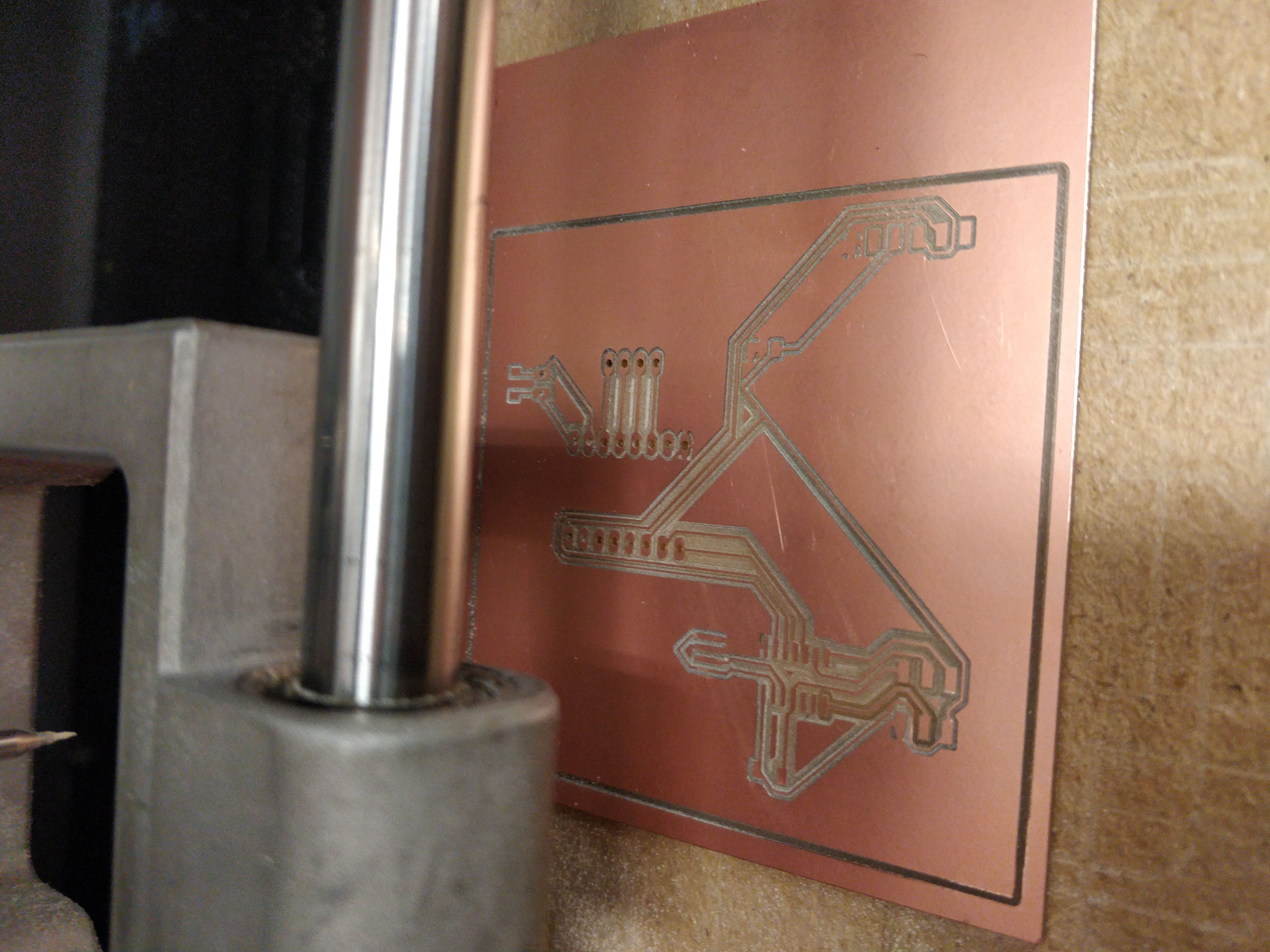
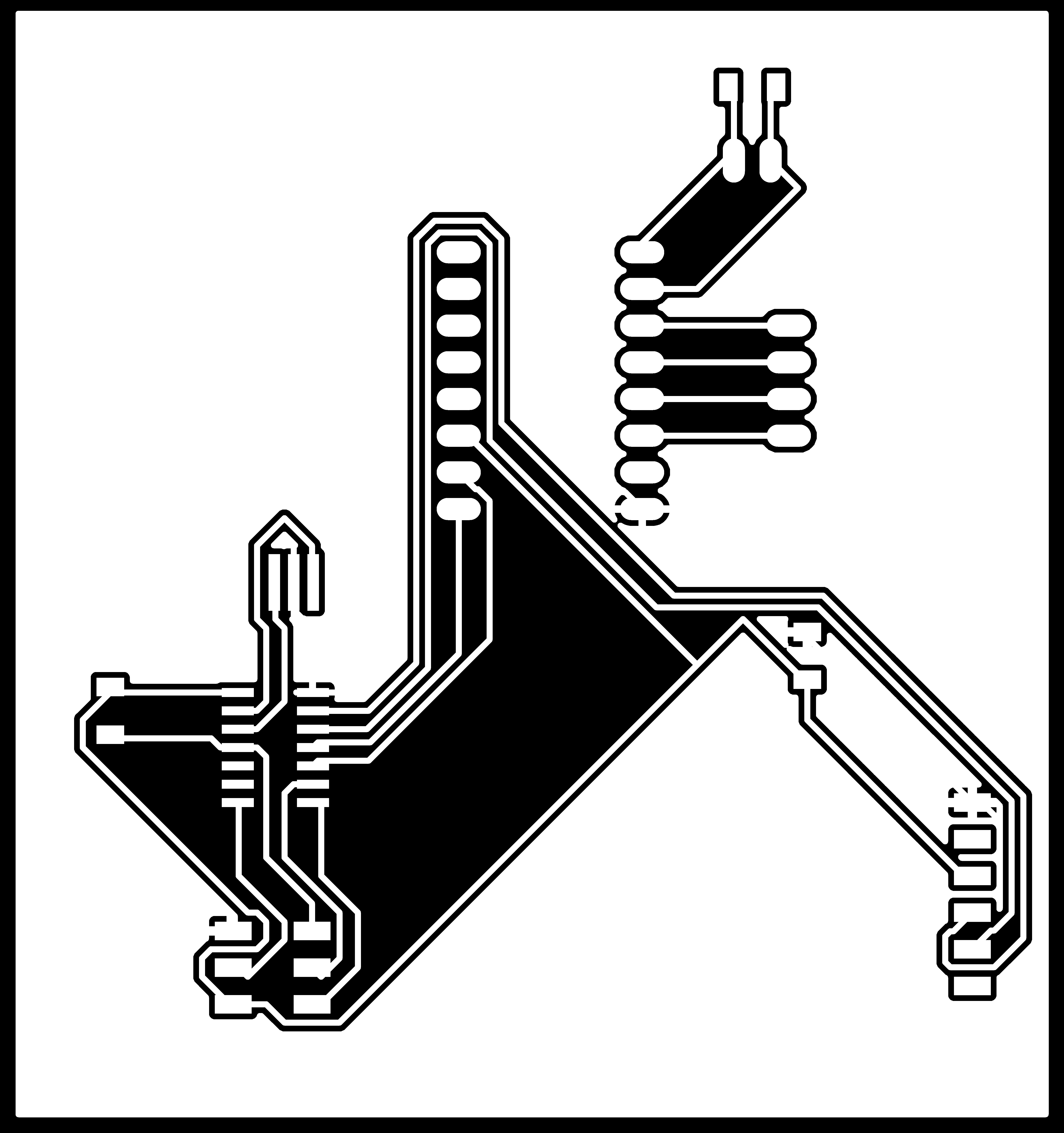
After the schematic, I designed the layout accordingly and exported the design into png files. Preparations for exporting the traces and outlines as well as the process of milling and soldering were explained the process in detail in Electronics Design week.
I used this list of components for soldering:
- Resonator 20MHz
- Capacitor 220uF
- Capacitor 1UF
- FTDI SMD Header (fab)
- ATtiny 44
- AVRISPSMD
- resistor 10k
- rails 8*1-2,2*1-1,4*1-1
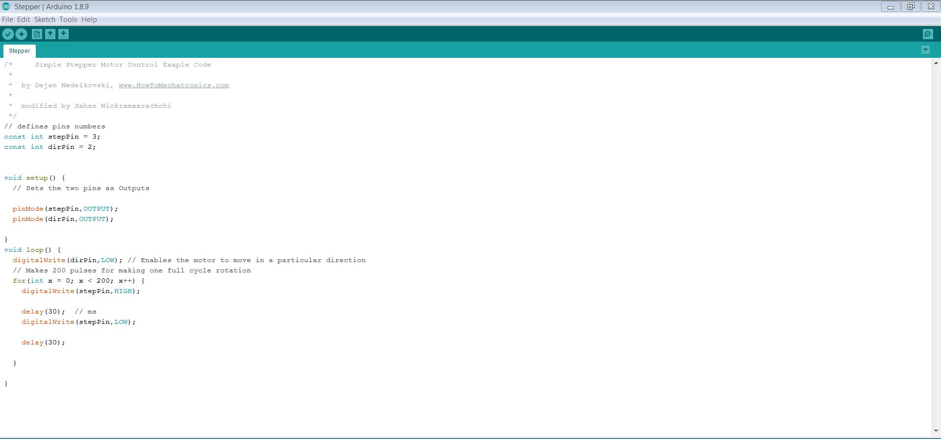
I used the Arduino sketch to program the board. First I referred to the ATTiny44A datasheet to check the pin numbers to program. I started to write a simple program referring to the example of Arduino and A4988 code..
In the code, it needs to define the step pin and direction pin for the stepper motor. The stepper motor which I used was 200 pulses for making one full cycle rotation, which means 1.8 degrees per step (360 degrees/ 200 pulses). We can control the rotation speed of the motor by changing the delay time.
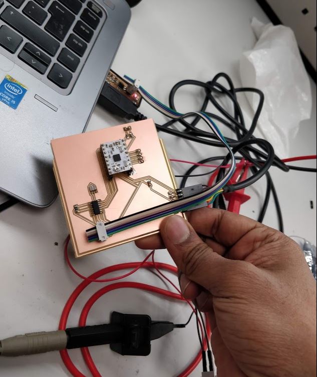
When I upload the code to the controller it did not work initially. After rigorous troubleshooting, I found out that some pins in the rails were not soldered properly. After soldering again them I uploaded the code. Then it started to work fine.
Group work:
For this task, we (Alok, Jobin, Sahan, and Yasir) measured the power consumption of a 5 mm LED and an RGB LED (the one used in the individual assignment above). The consumption of the LEDs was measured by directly powering them with a variable power supply and varying the voltage and current in order to measure the resulting effect on the brightness of the LEDs.
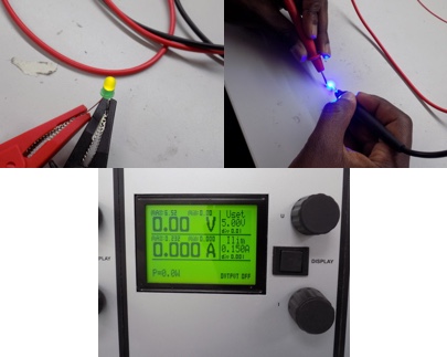
In both tests, we burnt out the LEDs by exceeding their voltage and current limits. For the 5 mm LED this was 6.5 V and 188 mA (it is probably lower than these values). Blue and Green LEDs can be fed with a maximum current of 100 mA (Peak Forward Current) for a very short time without being damaged 2. The peak forward current is the absolute maximum current that an LED can handle and this is only for a short period of time. The peak forward current, specified on a datasheet, can only be applied to an LED for the time period specified. This time period is either specified as a fraction of a duty cycle or as a time in milliseconds
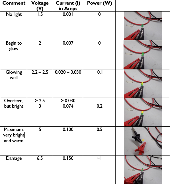
or the RGB, we repeated the same process as with the 5 mm LED, testing the effect of varying the voltage and current on the brightness. If current is increased the LEDs brighten and if decreased, the LEDs become dimmer. According to the data sheet, this LED has Forward Voltage ranging from 2 - 4 V. 2 - 2.6 V for Red, 3.2 - 4 V for Green, and 3.2 - 4 V for Blue. The absolute maximum ratings for the Forward Current (the current flowing across the LED from positive to negative in order for the LED to get power) for Red is 50 mA and for Green and Blue it is 25 mA (milliamps) when powered individually as we did. We tested the power consumption from a low of 1.60 V and 0.001 Amps, which didn’t power on the LED, to a high of 6.5 V and .200 A. Red was very dim at 1.9V and 0.001 Amps and the optimal value was 2.3 V and 20 mA. With the recommended electrical characteristics of 20 mA, Red has an average forward voltage of 2.0 V, Green 3.2 V, and Blue 3.2 V, respectively.
Models files
Outline for the trace
holes for milling
Eagle schematic design file
Eagle layout design file
RML file for traces
RML file for outline
RML file for holes
Modified Arduino code