Week 9. Embedded Programming
The main objectives were to read a microcontroller data sheet, program your board to do something with as many different programming languages and programming environments as possible. As the group assignment we had to Compare the performance and development workflows for other architectures
Reading a microcontroller datasheet
To begin with, I selected the data sheet for ATtiny44A microcontroller as it is used for my programmer. After going through the datasheet I got a general idea of how the ATTiny44A works.
It is a high Performance, low Power AVR 8-bit Microcontroller having advanced RISC architecture, in which most of the 120 instructions are executed in 'Single Clock Cycle Execution' and it has 32 x 8 general purpose working registers as well. In addition to that, it includes12 programmable I/O Lines (8 + 4) and the operating voltage is between 1.8 to 5.5V.
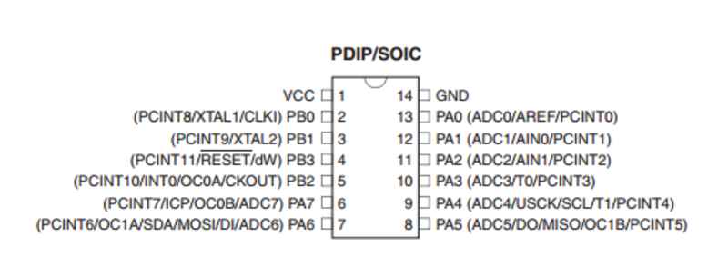
The ATtiny 44A pin configuration can be shown as below.
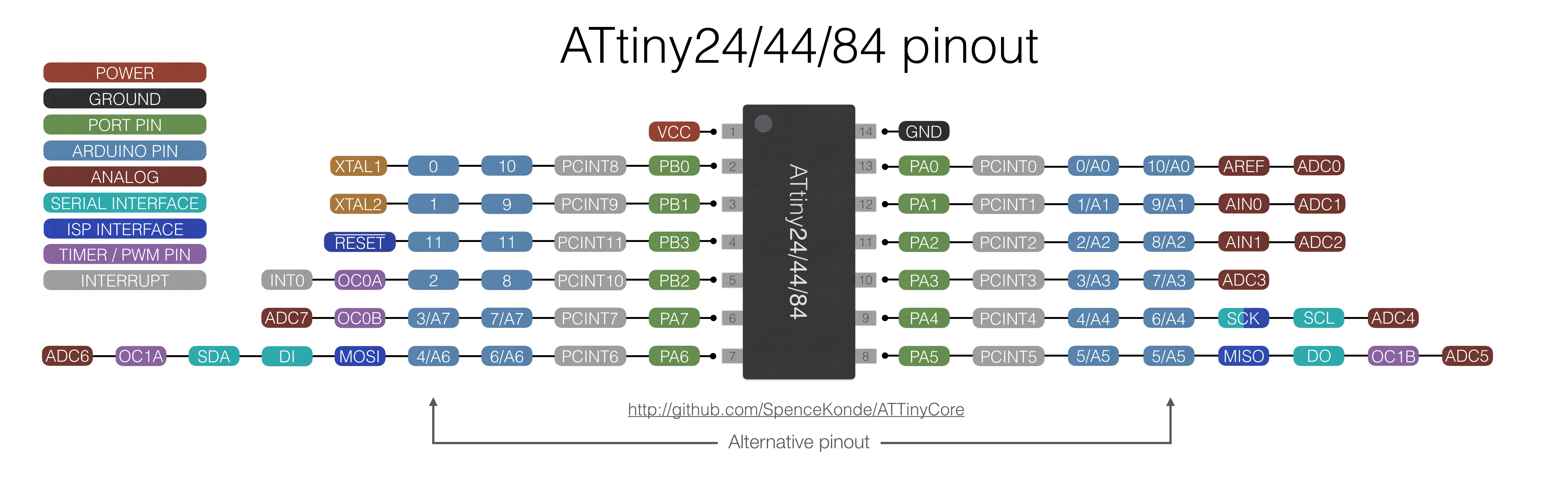
Pin mapping for the also shown here which is useful when programming the microcontroller. Refference
Embedded programming
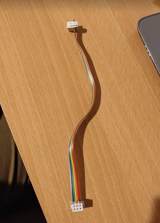
To begin with the programming, I created a new ISP cable. It required a ribbon cable and 2 pieces of 2x3 female connectors. After pressing the connectors into the cable to make the connections I was able to make the cable.
Programming the board
The operators for programming work on on the individual bits inside the byte. These are the basic operators used while programming.
- | bit OR
- & bit AND
- ~ bit NOT
- ^ bit XOR
- << bit LEFT SHIFT
- >> bit RIGHT SHIFT
The ATtiny44A version 14-pin SOIC has following Pin Configurations:
- VCC Supply voltage
- GND / Ground
- 8-bit port (PORTA) named PA7-PA0 bi-directional I/O port with internal pull-up resistors (selected for each bit)
- 4-pin port (PORTB) named PB0-PB3 bi-directional I/O port with internal pull-up resistors (selected for each bit)
- The direction of a pin is defined by registers (Data Direction register): DDRA and DDRB(Data is written to an OUTPUT pin using registers PORTA and PORTB.)
To start the programming the following items are required.
- FabTinyISP programmer
- ISP-programming cable
- extension cable for USB-port(optional)
- FTDI connector for USB-port.(Here the FTDI cable is needed to power the board because the programmer doesn't provide power for the programmable board.)
- I have also referred to my layout design and schematic from Week7.
Programming with Arduino IDE
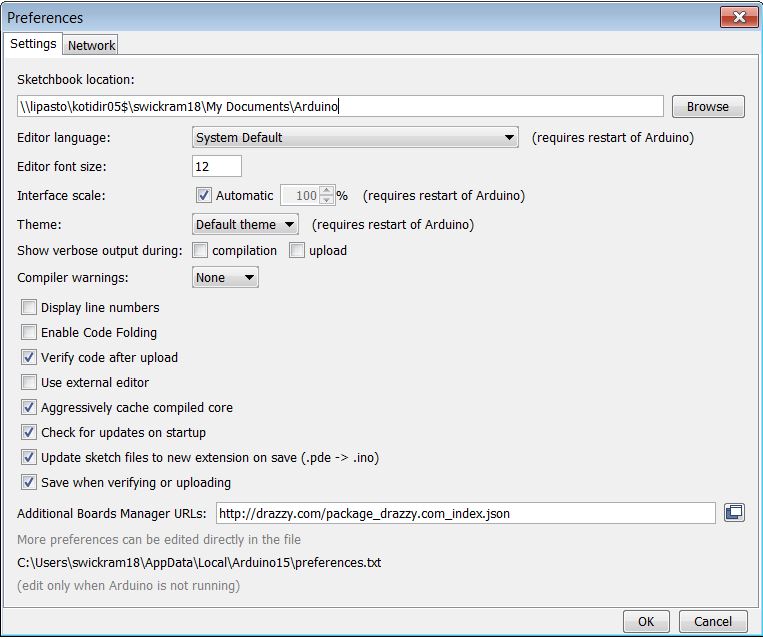
First I downloaded and installed Arduino IDE and the to setup it, I used the instructions given by SpenceKonde.
Go to File -> Preferences, and enter the URL http://drazzy.com/package_drazzy.com_index.json in "Additional Boards Manager URLs".
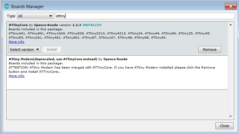
Then Tools -> Boards -> Boards Manager
Select "ATTinyCore by Spence Konde" and click "Install".
Next step is to select the following settings in the tools.
- Board ATtiny24/44/84
- Processor ATtiny44
- Clock External 20 MHz
- Serial Port [Check from the Device Manager ]
- Programmer USBtinyISP
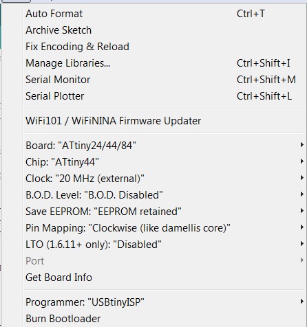
Before executing any code select Burn Bootloader option which will make the fuses and connect the board. For burning the bootloader, USBtinyISP needs to be connected.
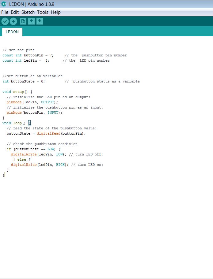
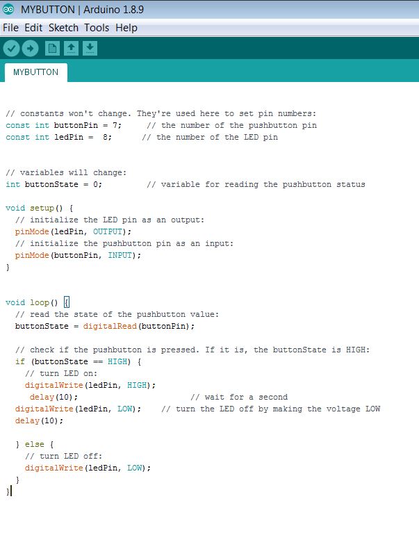
First I check the working of the board with the given examples from Arduino. The Button example was opened and executed initially. After putting the correct pins after checking I modified the code to work to turn the LED ON when the button is pressed and turning the LED OFF when the button is released.
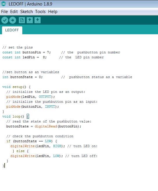
Next, I modified it to do the opposite in which it turns the LED OFF when the button is pressed and turning the LED ON when the button is released.
After that, I introduced a delay to the code and programmed the LED to blink when I pressed the button and to turn off when releasing the button.
Setting up Atmel Studio
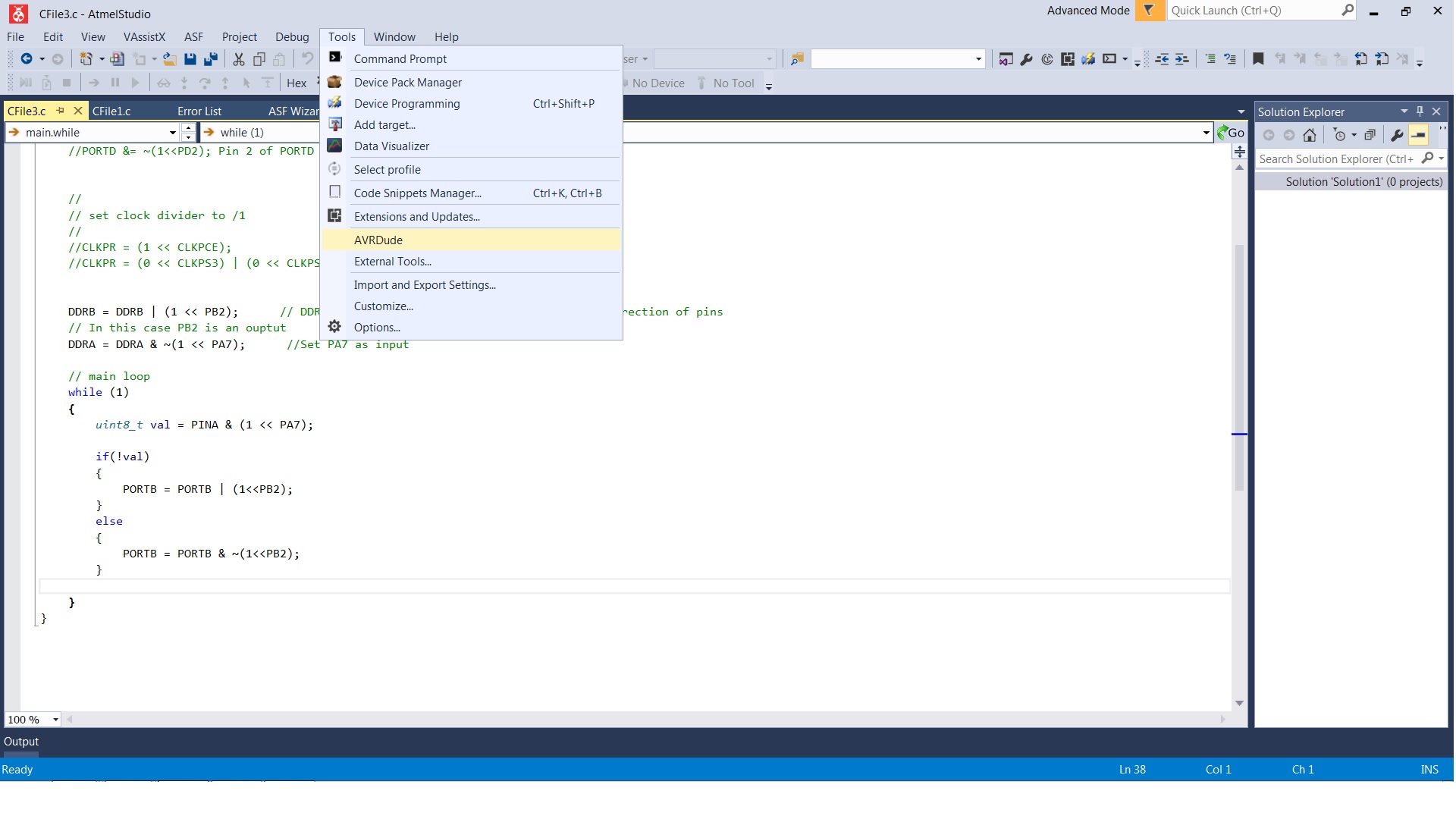
First I opened the Atmel studio software and added AVRDude tool using external tools, which will automatically program the board straight through from the location of built .hex -file.
First, navigate to the Tools > External Tools :
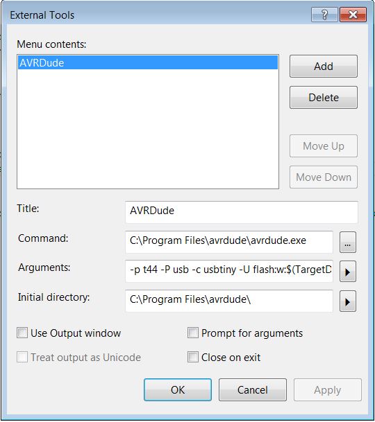
click Add for adding a new tool and following settings should be included.
- Title
AVRDude - Command
[path to avrdude.exe -file] - Arguments
[-p t44 -P usb -c usbtiny -U flash:w:$(TargetDir)$(TargetName).hex:i]
Here -p t44 describes the part number tells the programmable microcontroller [where t44 is short for ATtiny44]
-P usb tells avrdude the communication port to use to talk to the programmer
-c usbtinyspecifies the programmer type
-U flash:w: tells avrdude how to put data onto the chip and does programming; here, 'w' refers writing to 'flash' memory.
By clicking the arrow next to the row and select Target Directory and Target Name.
Initial directory [path to the avrdude.exe -folder]
Unselect Close on exit
Press Apply and OK
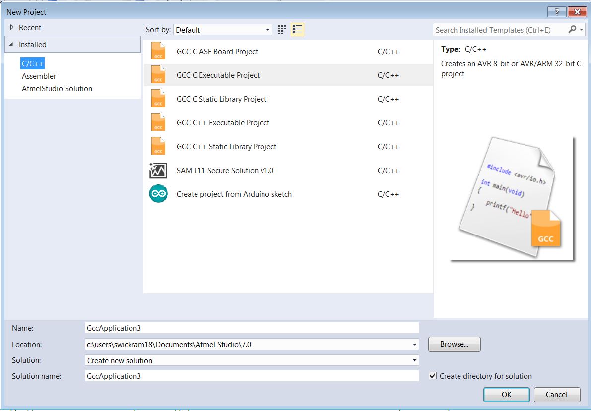
Next, I created a new project by navigating in the top bar to File > New > Project. From 'Installed' -tab select type C/C++ and GCC C Executable Project for creating an AVR 8-bit (or AVR/ARM 32-bit) C project and Name it.
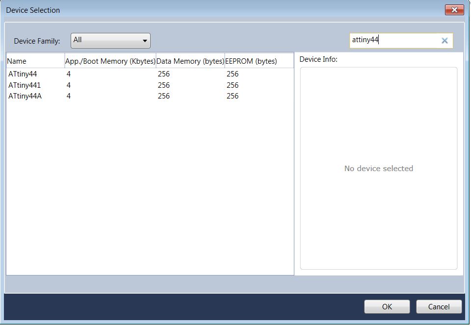
Then select the device as ATtiny44A from next window and Atmel Studio will create a new project.
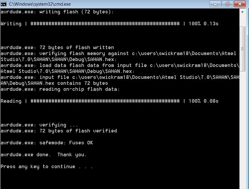
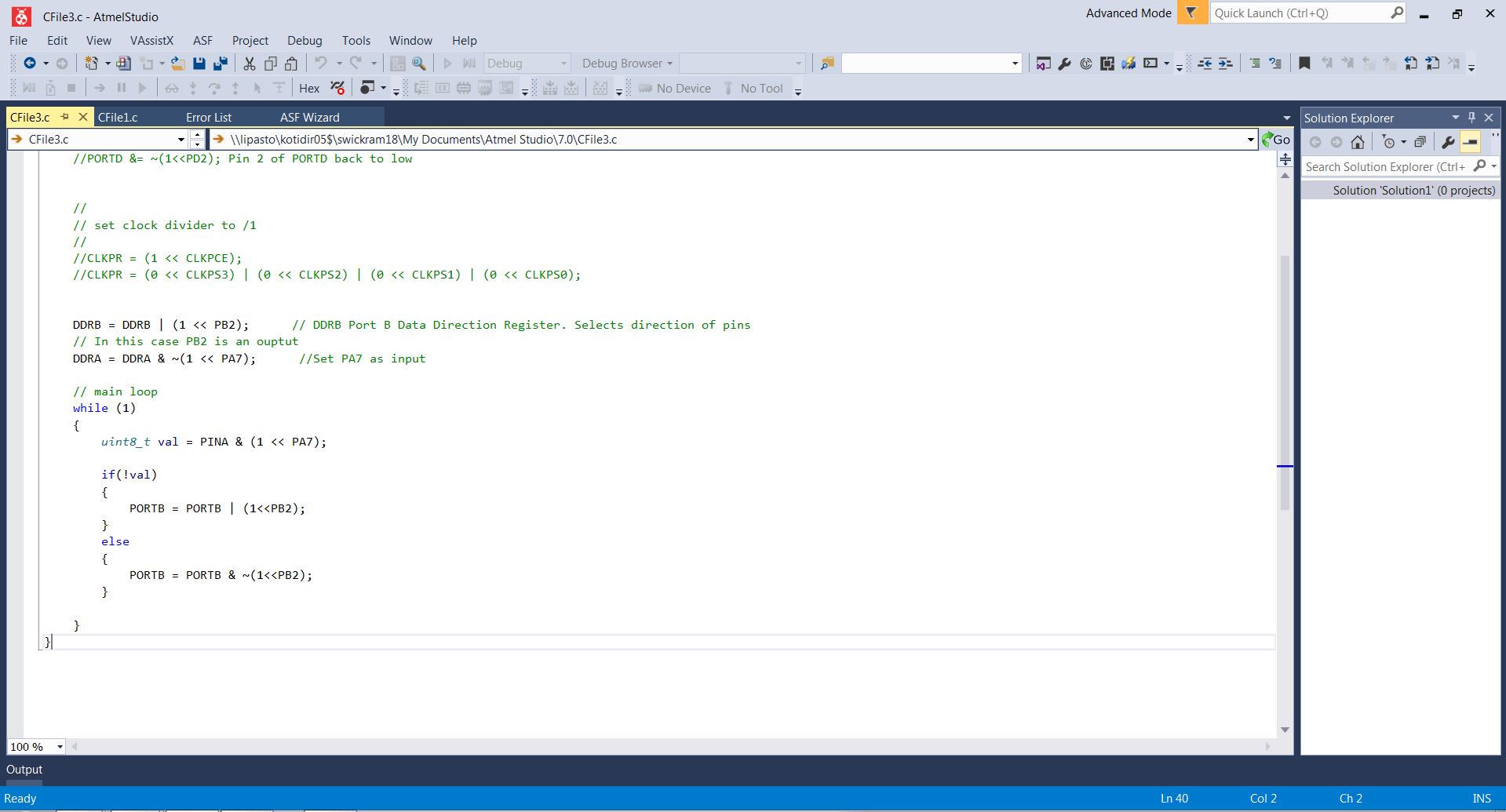
First, I used Ari's code to check the compatibility. First a. hex file can be created by navigating in the top bar Build > Build Solution. Then after connecting the two programmers to the computer and each other with FRC cable we can load avrdude by going to tools> avrdude. It will program the board.
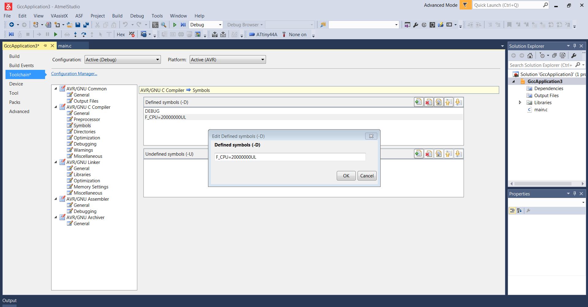
The clock speed for the board cat be set to 20MHz external clock in the code of the atmel studio. Here we define #define F_CPU 20000000UL // 20 MHz clock speed . In my case I already burned the bootloader on Arduino to set the external clock.
After hours of troubleshooting, it was found out that the code does not run with clock command on Atmel studio even though it works on Linux. The original code I got from Ari was not working when I execute it initially on Atmel studio. His code was working on Linux and on Linux it is needed to define the clock signal. Since I did the programming on Atmel studio it is not necessary to define the clock command on the code. Therefore I removed the clock signal and added it using the GCC application menu. After that code worked well.
Group work
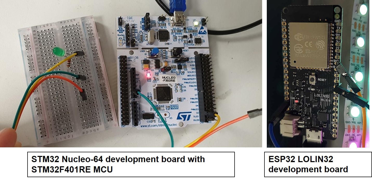
We worked together with the whole Oulu Academy group. We tested the STM32 Nucleo-64 development board with STM32F401RE MCU and ESP32 LOLIN32 development board using Arduino IDE. ST32 is a family of 32-bit microcontroller integrated circuits by STMicroelectronics. this group is related to same 32 bit ARM processor. The STM32 F4-series is the first group of STM32 microcontrollers based on the ARM Cortex-M4F core. The F4-series is also the first STM32 series to have DSP and floating point instructions. The F4 is pin-to-pin compatible with the STM32 F2-series and adds higher clock speed, 64 KB CCM static RAM, full duplex, improved real-time clock, and faster ADCs. All devices offer one 12-bit ADC, a low-power RTC, six general-purpose 16-bit timers including one PWM timer for motor control, two general-purpose 32-bit timers. They also feature standard and advanced communication interfaces.
More data can be found on the data sheet STM32F401x
While, ESP32 is a series of low-cost, low-power system on a chip microcontrollers with integrated Wi-Fi and dual-mode Bluetooth. The ESP32 series employs a Tensilica Xtensa LX6 microprocessor in both dual-core and single-core variations and includes in-built antenna switches, RF balun, power amplifier, low-noise receive amplifier, filters, and power-management modules. ESP32 is created and developed by Espressif Systems, a Shanghai-based Chinese company, and is manufactured by TSMC using their 40 nm process.
More data can be found on ESP32 LOLIN32
First, we install the Board manager for STM32F4 Boards ,followed by defining the board information in tools similar steps as that of ATtiny 44A board programming. Select board Nucleo-64, board part number Nucleo F303RE and run the blinking test code for the board setup.
First installing ESP32 board in Arduino IDE, detailed instructions see this Tutorial . Similar steps followed (see the individual assignment) for programing the ESP32 LOLIN32 development board. See the below first picture present STM32F4 and second picture which present LED blinking programmed for ESP32 board using Arduino IDE.
Reflection
I had troubles with setting up atmel studio coding with it initially. It consumed a lots of time to get it working. Comparatively coding on Arduino was easier. As part of the group assignment, we compare the performance and development workflow for other architecture STM32 and ESP32. I would like to get familiar with Atmel studio more.
Models files
Arduino -code to Turn OFF when pressed a button
Arduino -code to blink fast when pressed a button
Atmel Studio code to Turn a LED ON when pressed a button and OFF when released
Groupwork Codes