Week 14.Networking and Communications
this week objectives were to design, build and connect wired or wireless node(s) with network or bus addresses. For the group assignment, we had to send a message between two projects.
Group work:
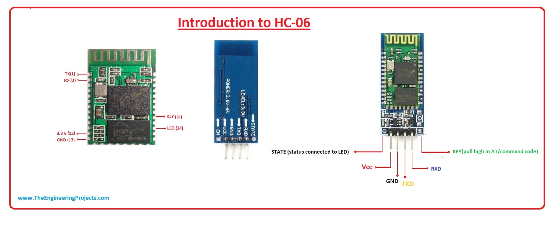
For this week’s group assignment, I worked with Micheal, Yasir, Jobin, and Alok. We have used the HC-06 Bluetooth slave module for wireless serial communication. we connected and programmed our boards from Electronics design week to blink the LEDs on the boards when a button on the Bluetooth mobile application is pressed.
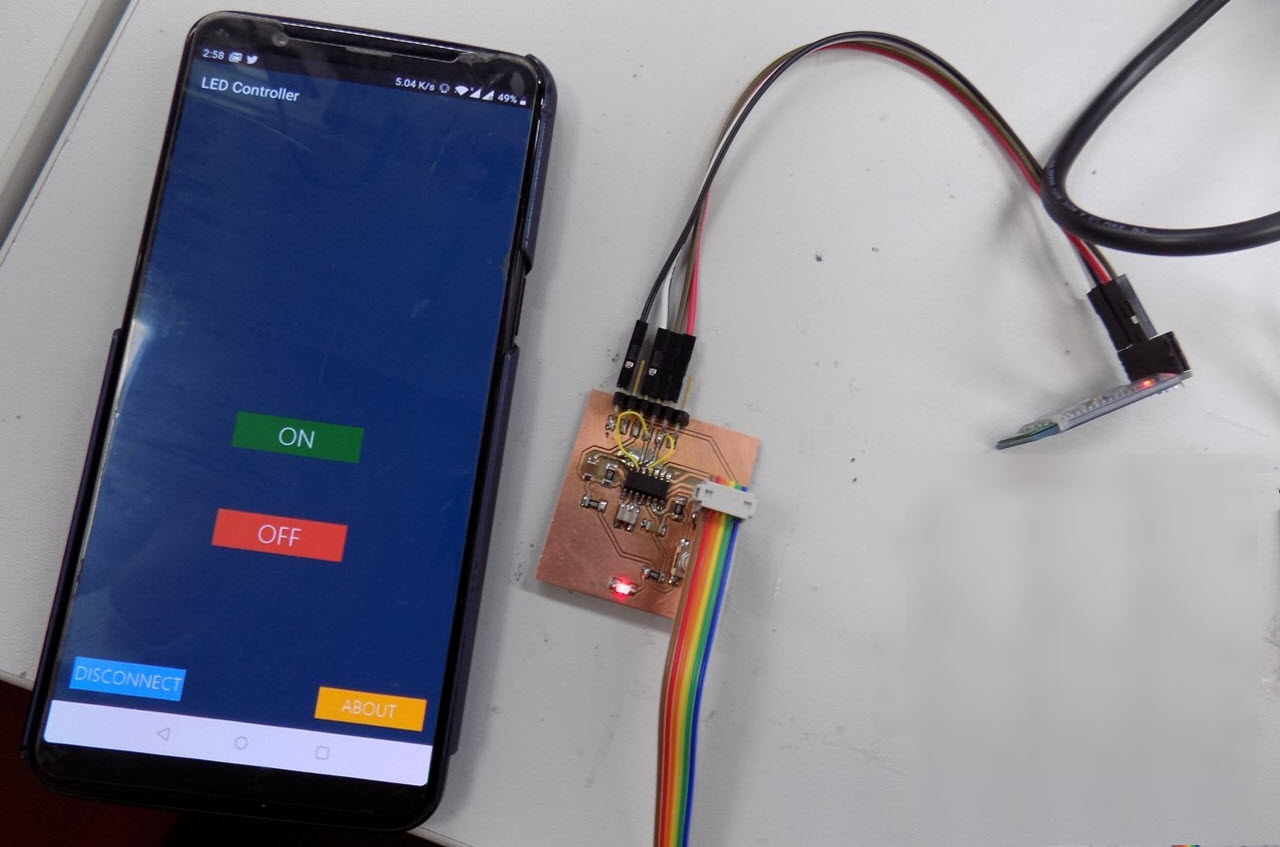
We have followed this tutorial for setting up our boards and the Bluetooth module. First, we tried with one microcontroller board and its LED. For that, we have used this app which was given in the tutorial.
In order to install an apk file it is needed to make sure that third-party apps are allowed on the device. After that just by simply downloading the apk file and touching on the file we can install the application. This is helpful if one does not know about apk files.
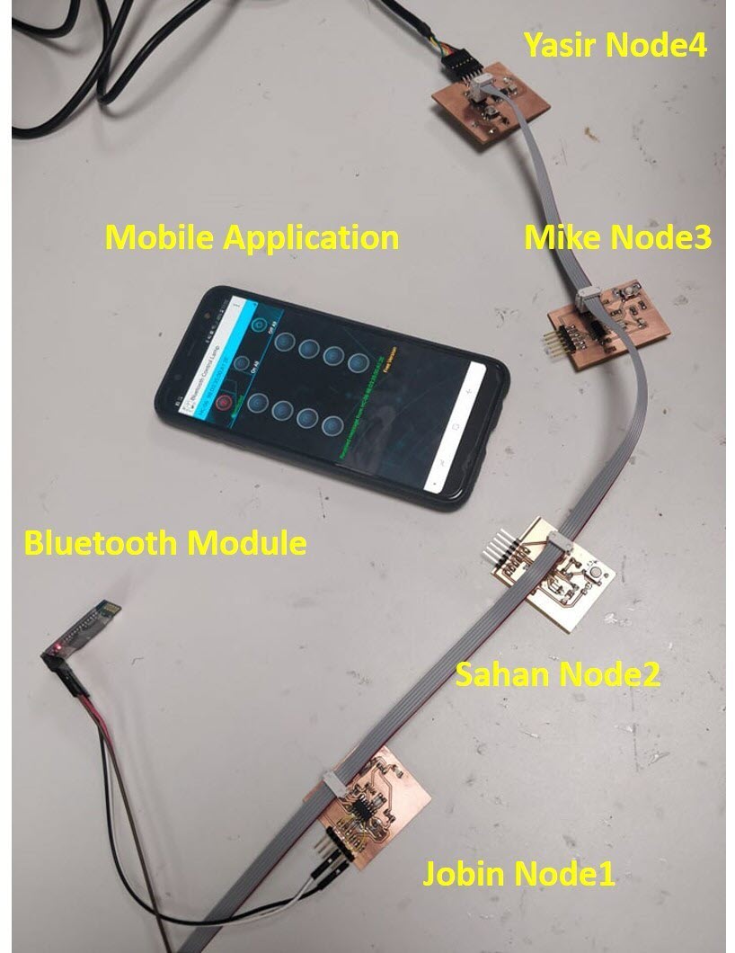
Later we connected few of our boards together to glow each LED when the letter corresponding to the number assigned to the node was pressed in the app.
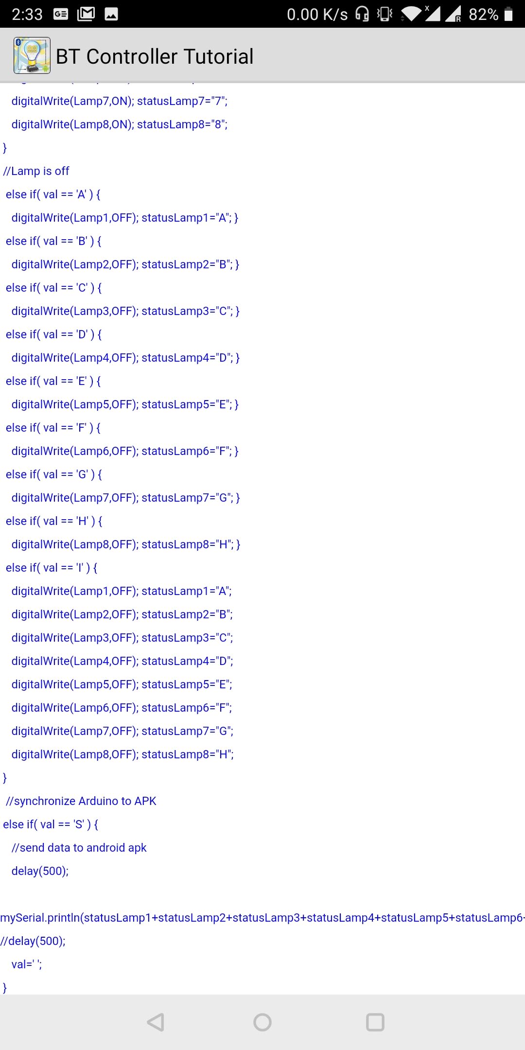
group work codes
code for the first node which was used between 2 nodescode for the second node which was used between 2 nodes
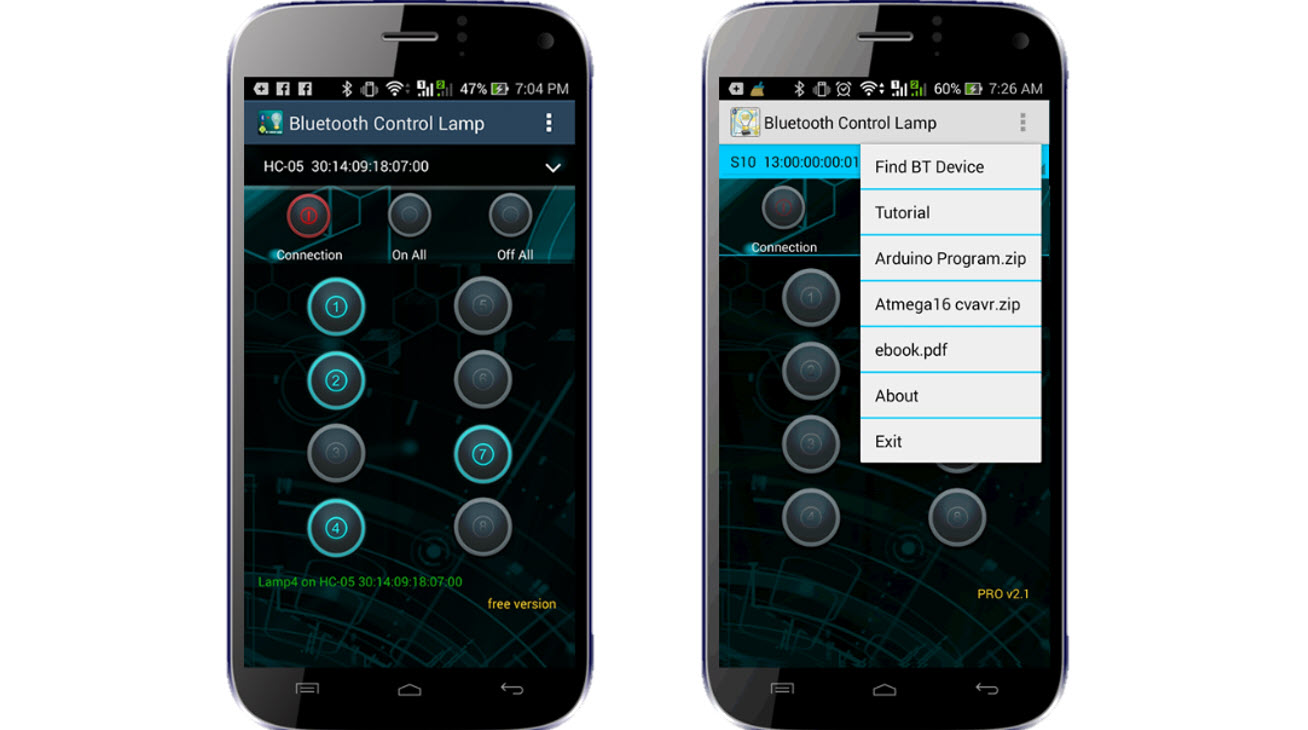
Finally, the code was modified so that all the LEDs turned on and off at the same time using the app.Later we used different app to control the boards.
The circuit is so simple and small, there are only a few connections to be made
Attiny Pins ———-> Bluetooth module Pins
RX 	Bus	        ———->      TX Bus

TX  Bus         ———->      RX Bus

5V       	    ———->      VCC

GND             ———->      GND
GND and VCC were provided from one board and all the boards were connected using FRC cable which we made. Next, we connected the Bluetooth module to one board with the above pins. We programmed each board separately to respond to different commands sent by the app.
group work codes
code for the first node which was used between 4 nodescode for the second node which was used between 4 nodes
code for the third node which was used between 4 nodes
code for the fourth node which was used between 4 nodes
Individual work:
As per the individual work I have used the same Bluetooth module HC-06 to control the stepper motor and a LED of my controller board. The communication protocol used here is blutooth. HC-06 Bluetooth module can only be in slave mode and needs a master node (e.g. smart phone or Bluetooth enabled PC) to initiate connection. I have used the same app which was used to communicate between multiple nodes. It was downloaded from google app store It includes a tutorial page which is very helpful for the communication process. The app send a Letter corresponding to the button we press on the app. These can be found on the tutorial page. The board from my output week has been used here to control the stepper motor.
I connected the HC-06 to the microcontroller board and it was connected with stepper motor controller board with ISP cable. I programmed the stepper board and microcontroller board separately to respond to the commands sent by the app.
Stepper Control code
  #include < SoftwareSerial.h >
#define txPin 4     // PA0(MISO) transmit signal to the bridge
#define rxPin 5     // PA1(SCK) recieves signal from bridge

SoftwareSerial mySerial(rxPin,txPin);

const int stepPin = 3;
const int dirPin = 2;

char Incoming_value = 0;                //Variable for storing Incoming_value
void setup()
{
  mySerial.begin(9600);         //Sets the data rate in bits per second (baud) for serial data transmission
  pinMode(txPin, INPUT);   //default tx as input
  pinMode(stepPin,OUTPUT);
  pinMode(dirPin,OUTPUT);

}
void loop()
{
  if(mySerial.available() > 0)
  {
    Incoming_value = mySerial.read();      //Read the incoming data and store it into variable Incoming_value
    mySerial.print(Incoming_value);        //Print Value of Incoming_value in Serial monitor
    mySerial.print("\n");        //New line
    if(Incoming_value == '2')            //Checks whether value of Incoming_value is equal to 2
    {
      digitalWrite(dirPin,LOW); // Enables the motor to move in a particular direction
  // Makes 200 pulses for making one full cycle rotation
  for(int x = 0; x < 1000; x++) {
    digitalWrite(stepPin,HIGH);

    delay(1);  // ms
    digitalWrite(stepPin,LOW);

    delay(1);

    if(Incoming_value == 'B')       //Checks whether value of Incoming_value is equal to B
     { digitalWrite(dirPin,LOW);   //If value is B then set dir low and Step low
       digitalWrite(stepPin,LOW);
     }

     else if(Incoming_value == 'I')       //Checks whether value of Incoming_value is equal to 0
     { digitalWrite(dirPin,LOW);    //If value is I then set dir low and Step low
       digitalWrite(stepPin,LOW);

     }

  }
    }

           else if(Incoming_value == '9')            //Checks whether value of Incoming_value is equal to 1
    {
      digitalWrite(dirPin,LOW); // Enables the motor to move in a particular direction
  // Makes 200 pulses for making one full cycle rotation
  for(int x = 0; x < 1000; x++) {
    digitalWrite(stepPin,HIGH);

    delay(1);  // ms
    digitalWrite(stepPin,LOW);

    delay(1);

  if(Incoming_value == 'I')       //Checks whether value of Incoming_value is equal to 0
     { digitalWrite(dirPin,LOW);    //If value is I then set dir low and Step low
       digitalWrite(stepPin,LOW);

     }

  }
    }

  }

}
Model files
Individual work codes
code for the first controller node which was used between stepper and controller nodescode for the second stepper board which was used between stepper and controller nodes