Week 8. COMPUTER-CONTROLLED MACHINING
The main objectives were to Test runout, alignment, speeds, feeds, and toolpaths for your machine. Individual assignment to make something big on a CNC machine.
Group work
Initially, an introductory session was given by local instructor Eino. We were guided through the design of a 3D model in Fusion 360, how to get the toolpaths in CAM workspace and, finally, how to prepare the machine and cut the model.
To begin with the design,we were told that the wood-router table size ~1,3m x 3m so that we have to make our design accordingly. Moreover, the thickness of the sheet provided was 11mm approximately.
First, we designed the model using fusion 360. After the design, the toolpaths were created. The following steps were followed while creating tool paths. We need to download two files for CAM post processor and The file for tooling values for different routing bits. The CAM post processor file used to create the Post Process, so when creating the file for the CNC machine. Tool value file used to select the Tool when pockets and contours created. Making of the NC file will be explained in detail for the individual assignment below.
Using the machine
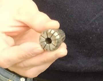
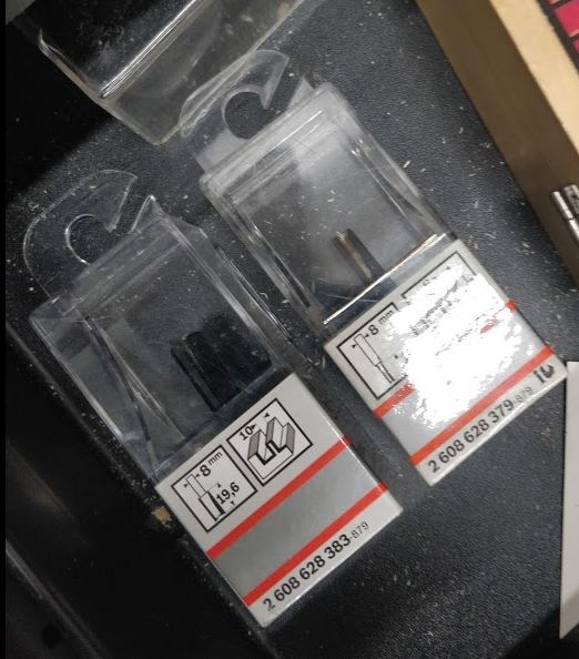
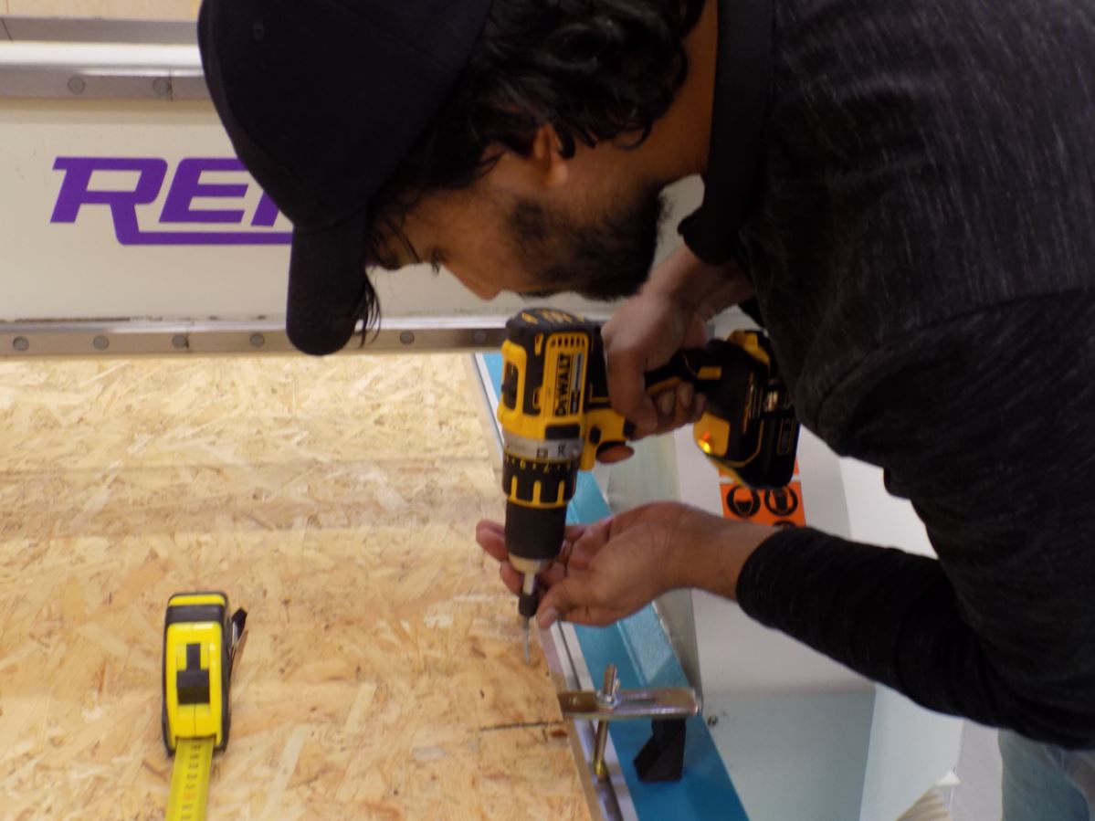
Rensi E2-1234 CNC router is used in our Fablab and for this design, We used an 8mm flat milling bit. First, we needed to attach the mill bit to the clamp before cutting.
For safety, we need to follow the below instructions
- Always Use protective glasses. Earmuffs are recommended.
- The suction must be activated always while operating the machine so all dust can be removed.
- Do not start it until you know how to stop it
- Do not leave the machine working without supervision
The process
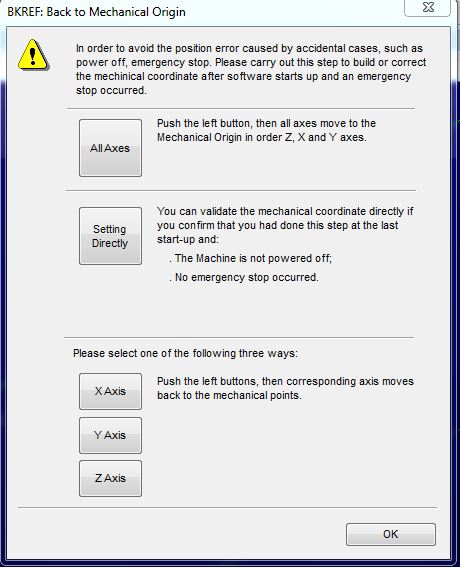
First, open the CNC studio software which controls the machine. Then we need to set the machine zero (mechanical origin). Put the board on the machine platform and screw it well.
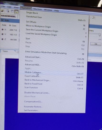
To set the origins, in the prompt window, press All Axes, and the machine does it automatically. If not it also can be done manually. To set the x and y origin we need to press X and Y buttons as needed. The hand wheel also can be used to move the milling head. To set the Z origin we can use the auto calibrator. Put the calibrator below the milling bit and from the CNC studio select Operation > Mobile calibrator. Then the z-axis will be calibrated automatically. The feed rate was 80% of the maximum 6000 mm/min to 4800 mm/min. Spindle speed is 80% of the maximum 15000 rpm-12000 rpm
Result analysis
Here are the files of the test part made for the group work.
Test part (Step file)
Test part (NC file)
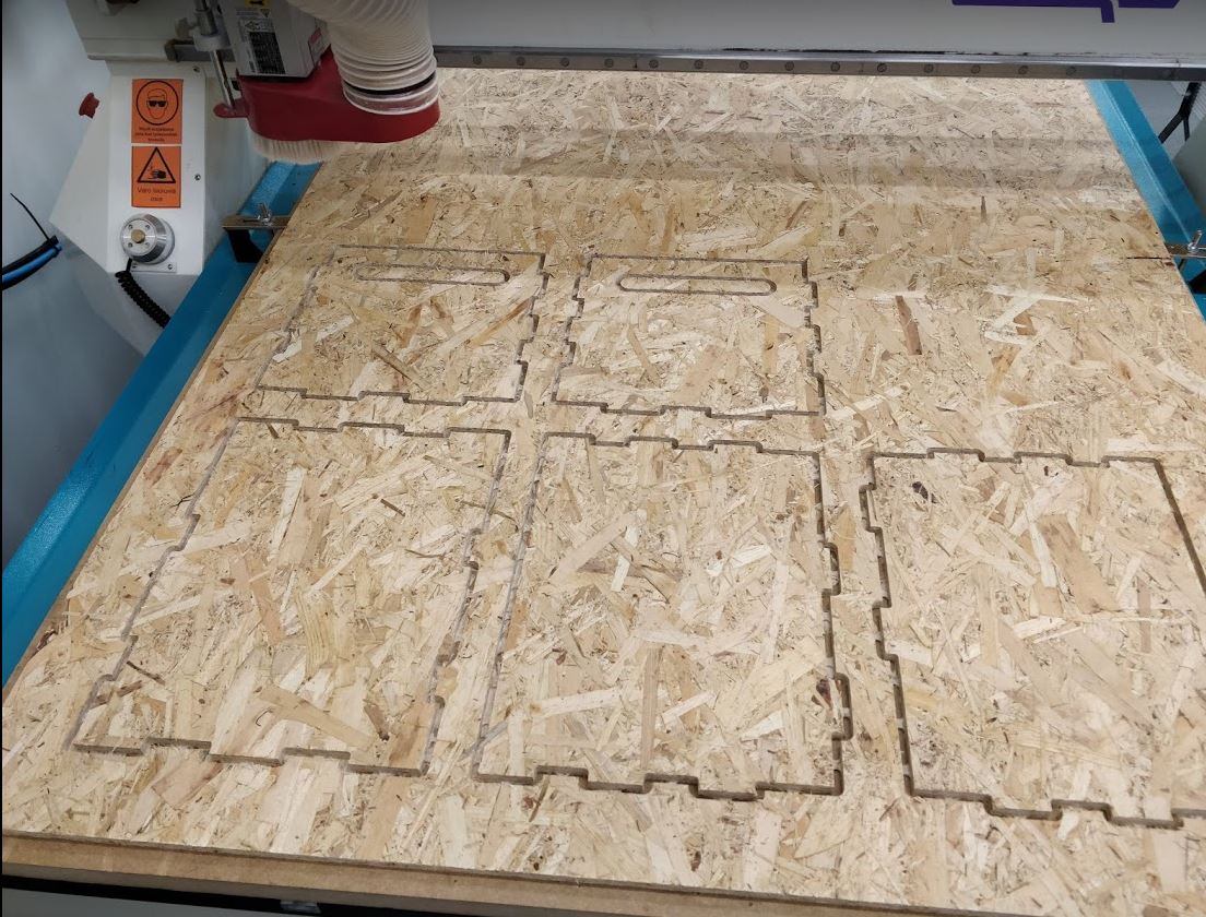
The machine setup was: 8 mm 2 flat milling bit. The final result after cutting is shown below.
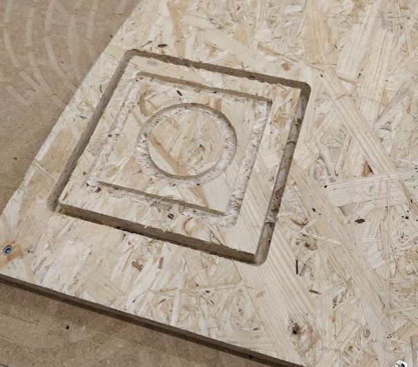
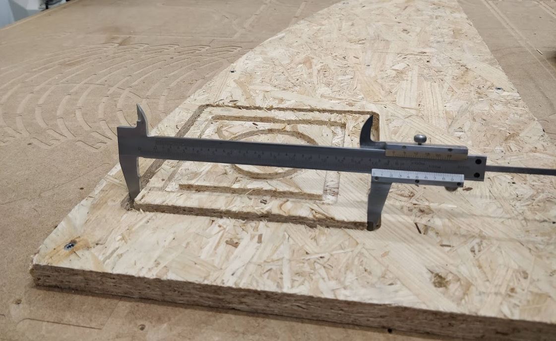
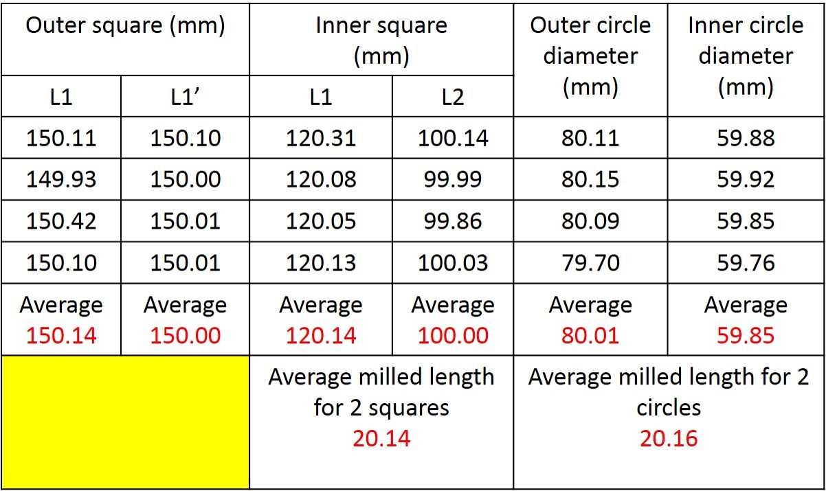
We have measured the average milling length for 2 squares is 20.14 mm while the average milling length for the 2 circles is 20.16 mm. Both the values are close, and error is minimal in comparison with the 3D design file.
Similarly, we also documented the engraved area from the square, and circular engrave thickness measured before and after milling using digital screw gauge. See the results and difference in thickness from the square area and the circular area from the below table.
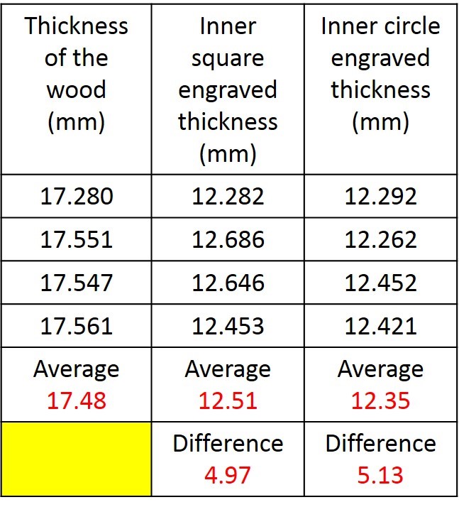
Target design values are, L1 = L1’ = 150 mm, square L1 = 120 mm, L2 = 100 mm, Outer circle diameter = 80 mm and Inner circle diameter = 60 mm and thickness of the wood board used is 18 mm and Engraved area is 5 mm. Here also we observe the difference is very little in comparison with the 3D design
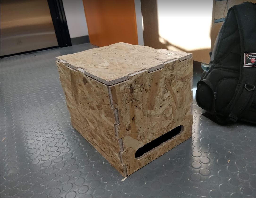
Individual assignment
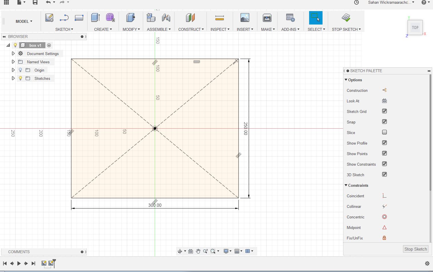
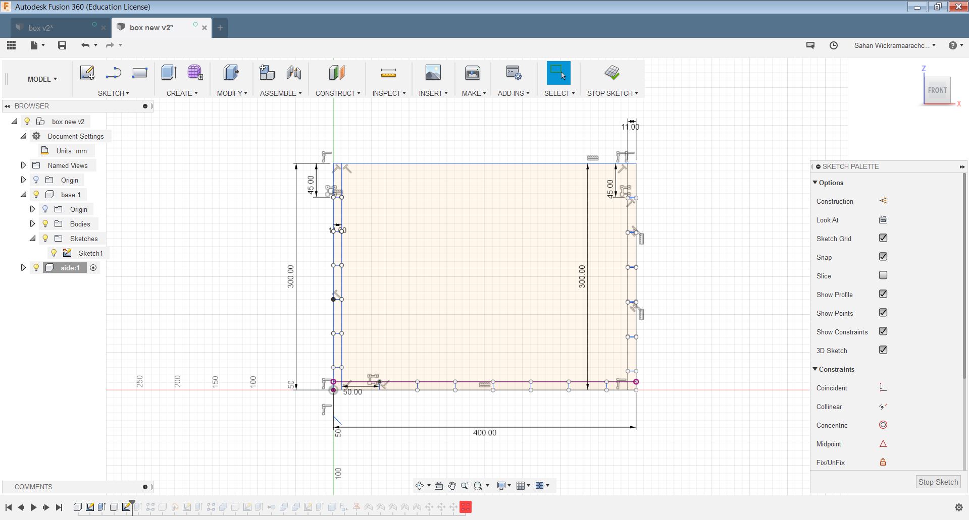
I used the Fusion 360 for making my design. First I made a bottom plane by creating a rectangle and extruding it 11mm as the thickness of my board.
Then I created custom parameters for Length, width, and the thickness. I changed the appearance of the material to wood from metal. Then I created a component from the body.
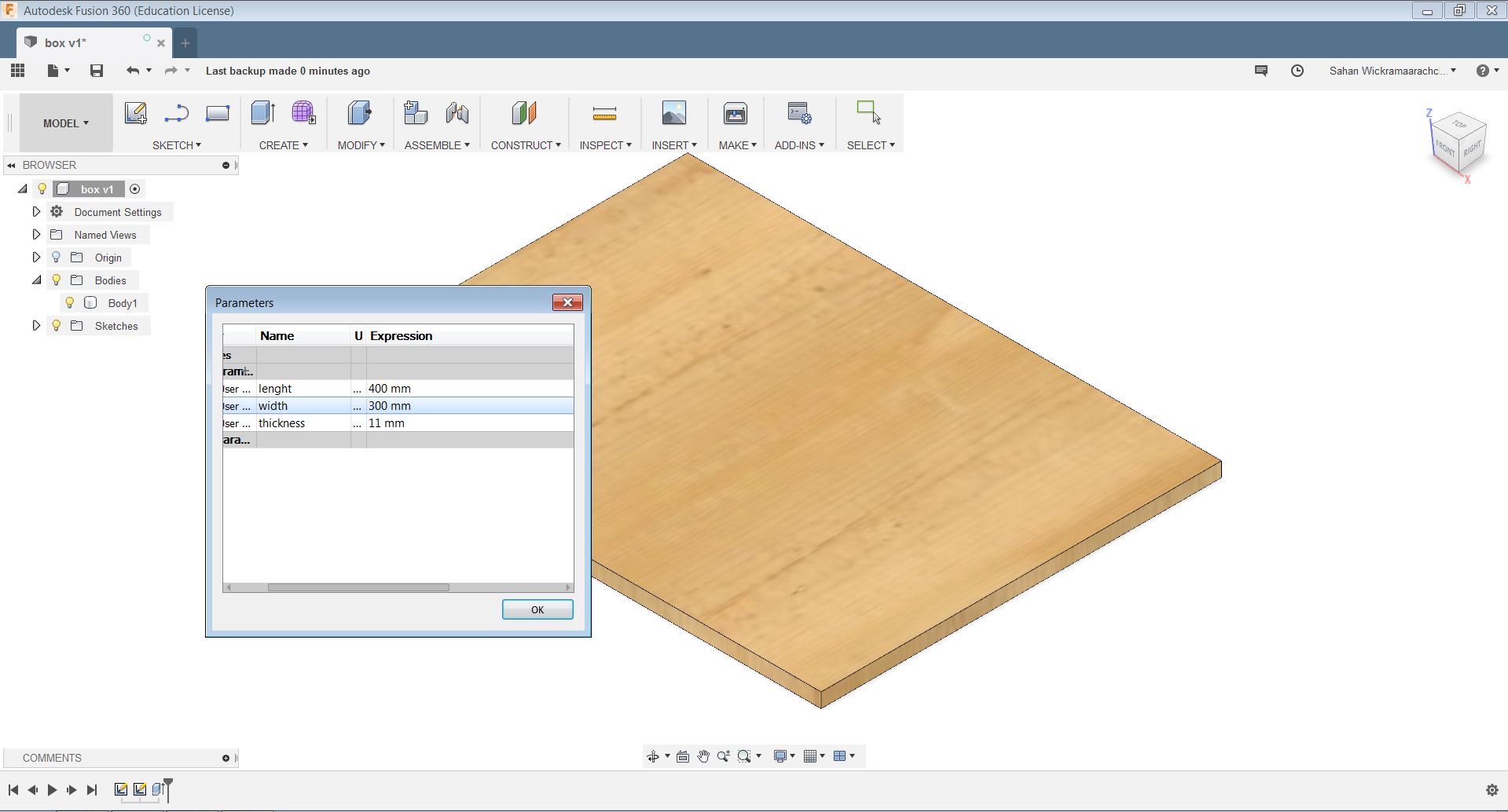
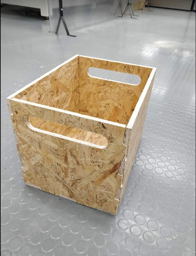
After creating a new component for the side walls I did the same as making the bottom plane. Here the height is used as 300mm and the width is 400mm. Then I added the small cut components. Then extruded it 11mm.
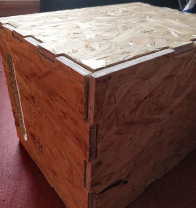
Next, I created other side walls in the same manner. After that, I combined all the components and cut the extra parts.
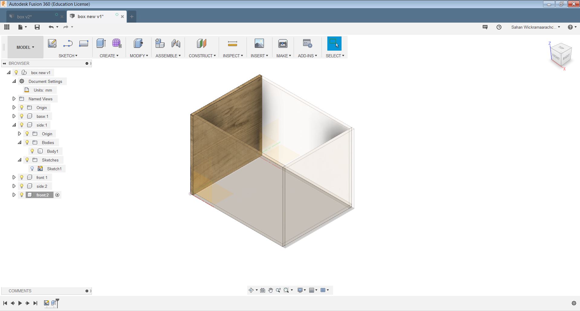

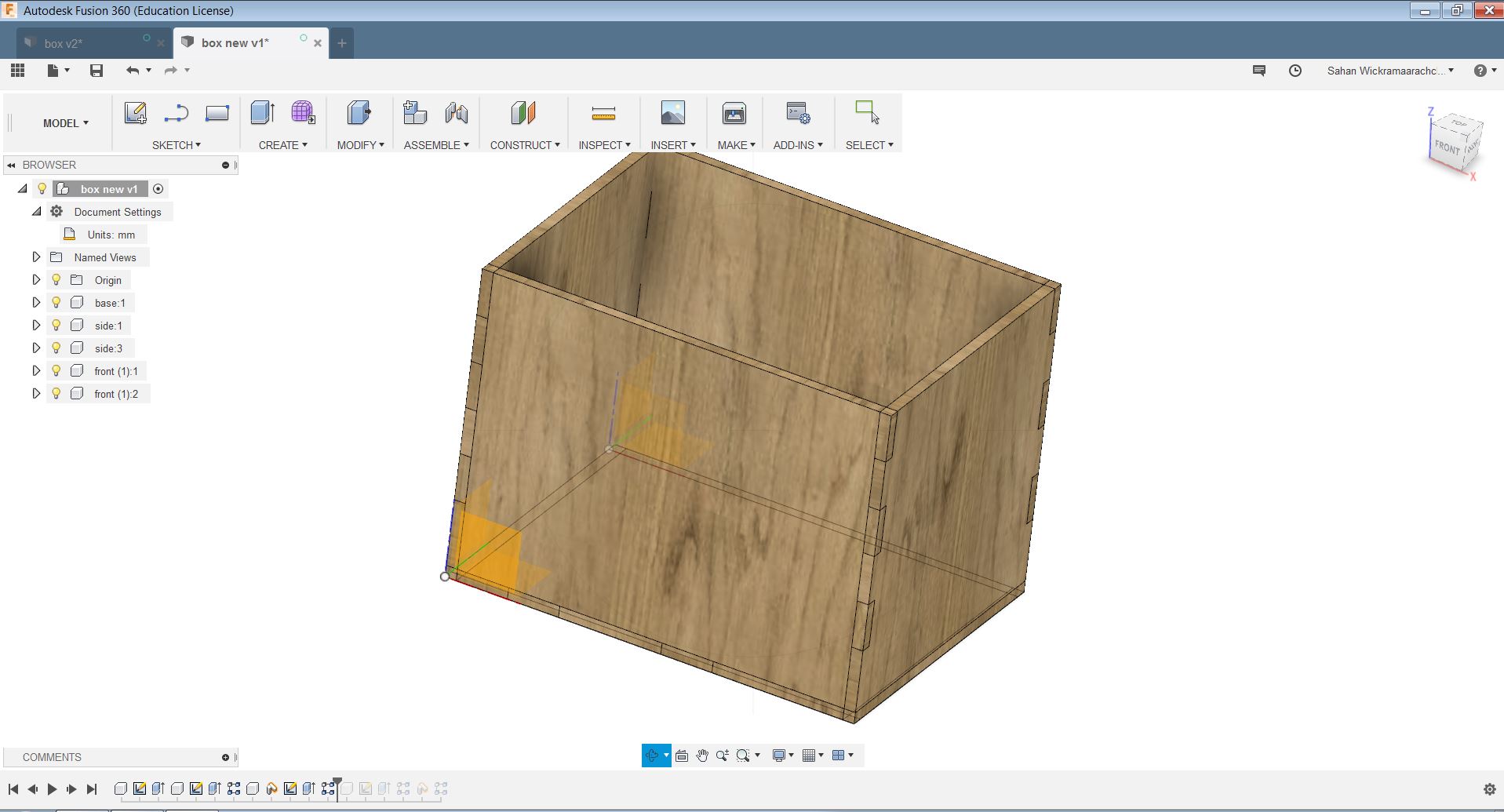
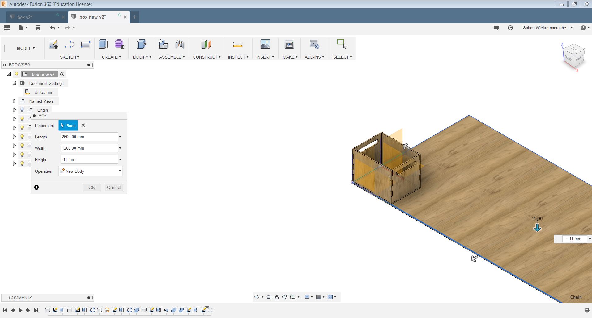
Next step was to create a box feature to place the components in the plane. The OSB board used to make the design here is 11mm thick, it is 1200mm wide, and it is 2600mm tall therefore I made the box according to that.
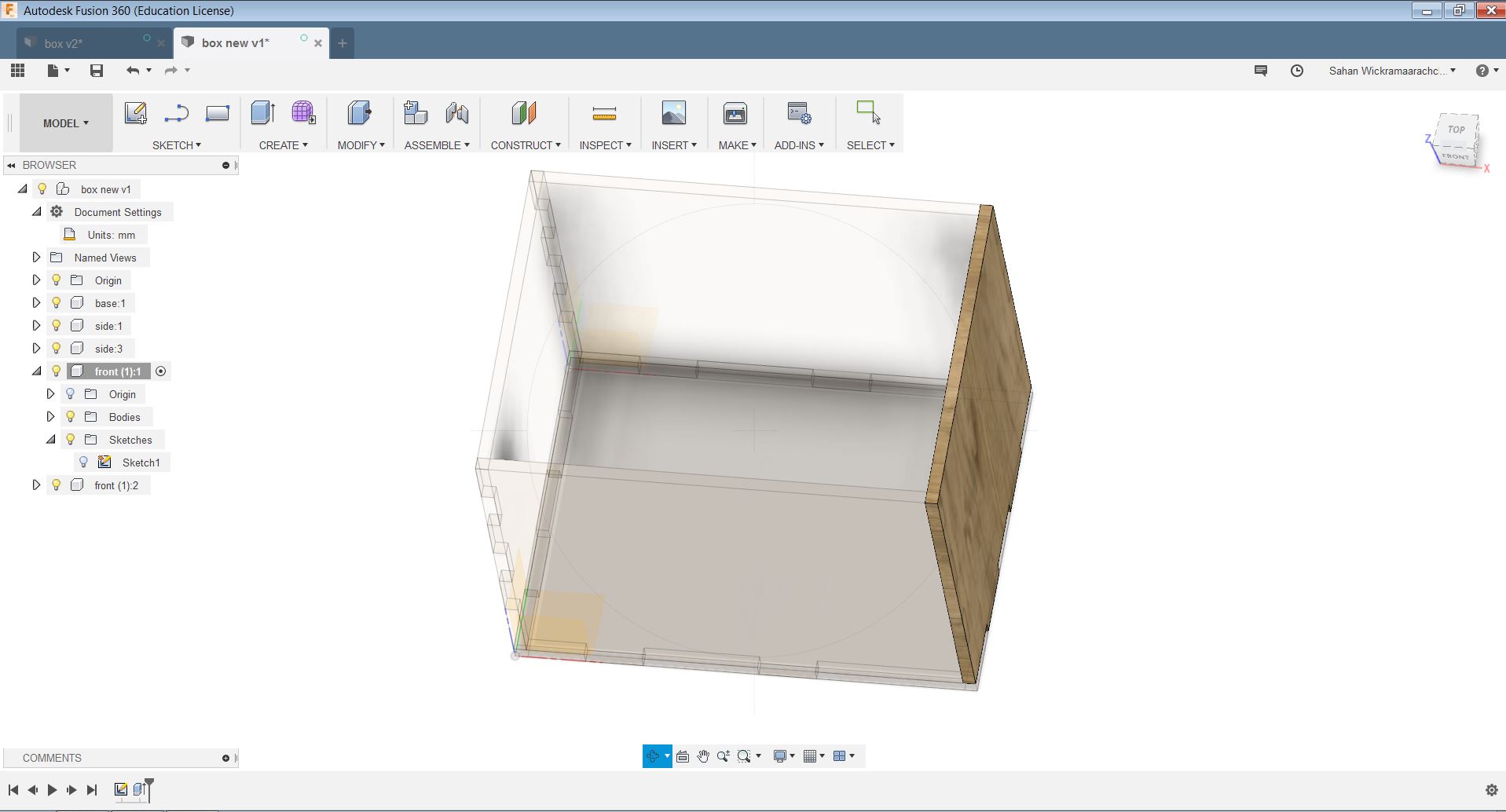
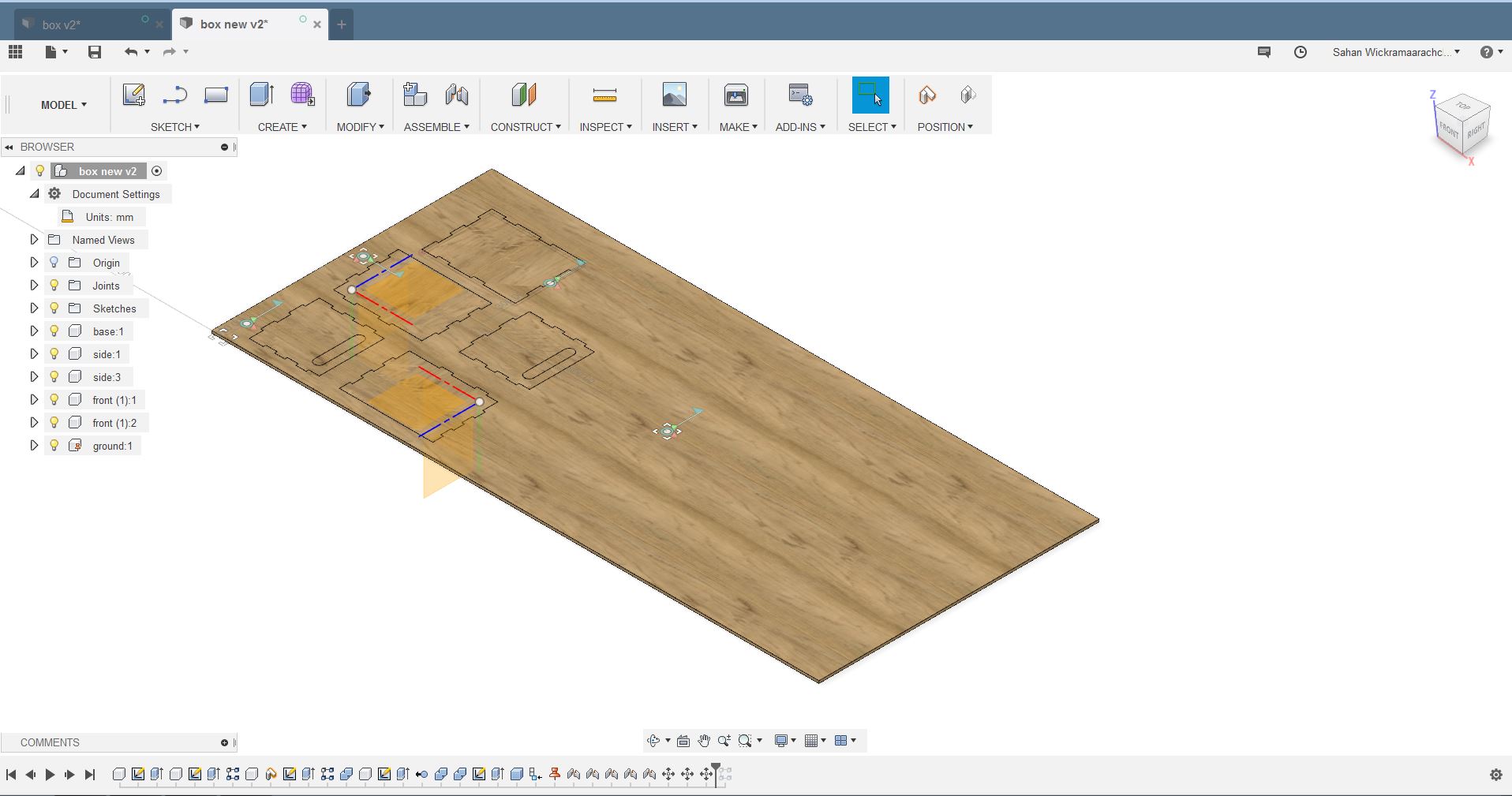
After that, make 'ground' the stock component to keep it from moving around. this can be done by selecting the stock component from the tree on the left, right-clicking, and selecting ground.
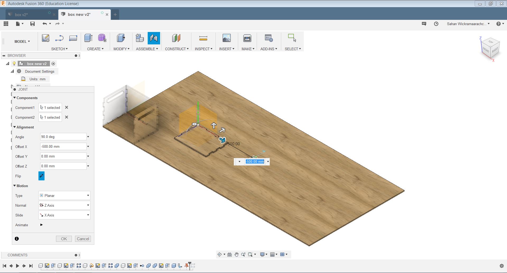
To lay the parts on the sheet, use the assemble>joint feature (shortcut J). Then select one the component that needs to be placed as the component 1 and the sheet as component 2. Then tick the "flip" feature to get the parts facing up. Then do this for all components and place them well.
Createing tool path
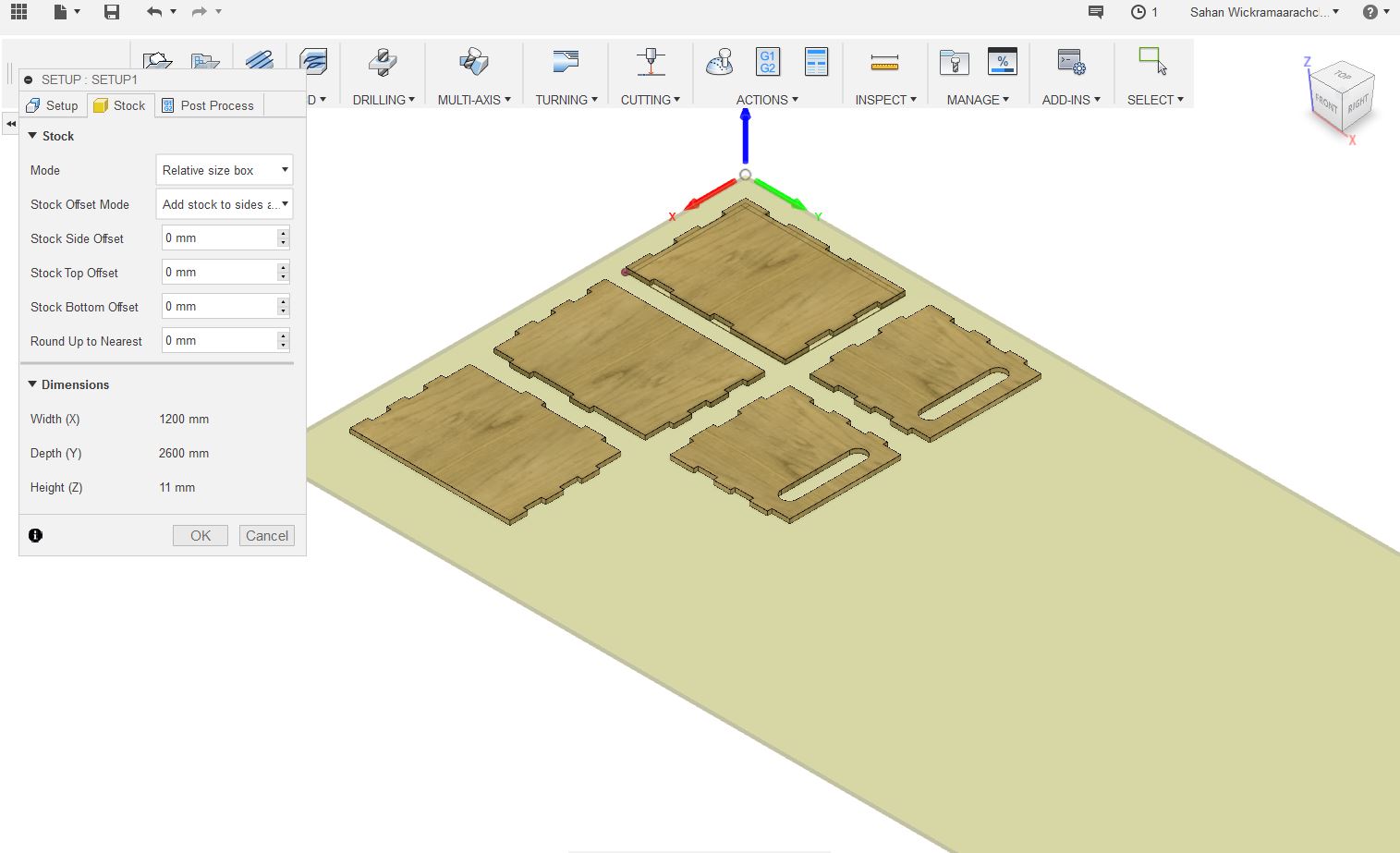
To create a tool path go to the manufacturing menu. Then right-click the setup and create a new setup

Setup the Operation type to Milling. Then set up the work coordinate system Setting the orientation as Select X & Y axes as needed. In the stock tab set stock values to 0mm.
I only had to cut the outlines so I created 2D contour. All contour settings are shown below.
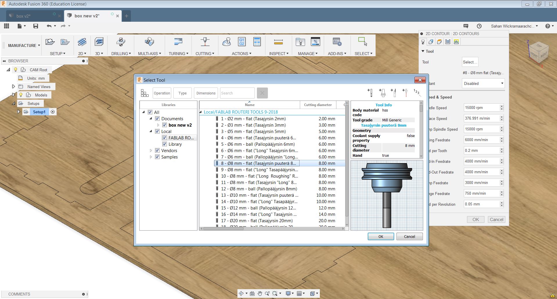
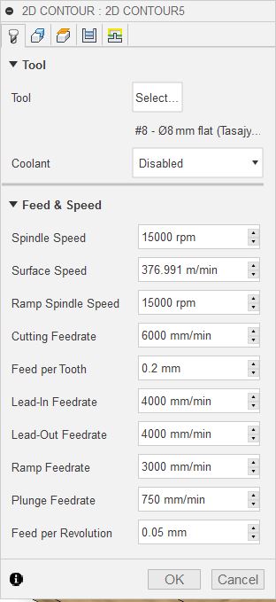
First we need to select the mill bit which we are going to use from the tool menu. Then set the spindle speed to 15000rpm.
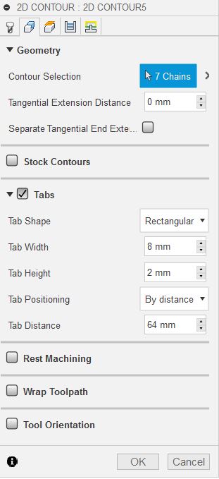
Then select the outlines of the design in the next geomatry menu. Here enable tabs option with tab width of 8mm and tab height of 2mm.
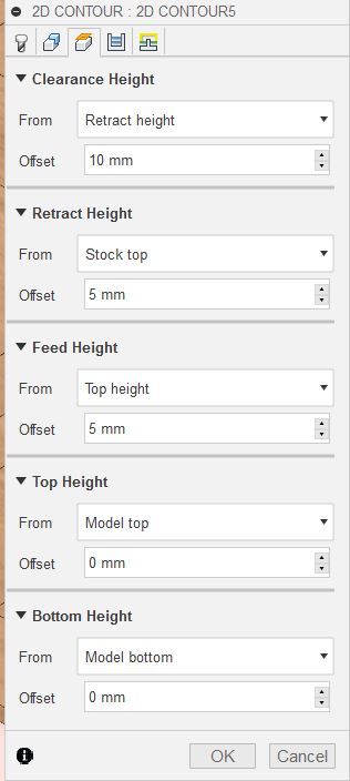
After that change the top height and the bottom height of the design to model height and model bottom. Set the clearance height to 10mm and the feed height to 5mm as well as top and bottom height 0mm.
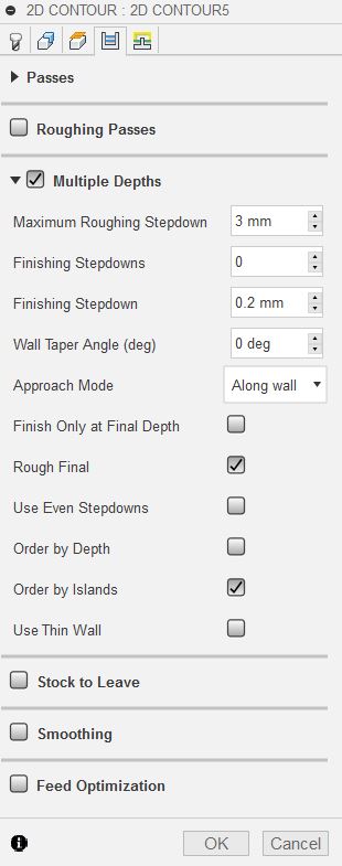
from the next menu, select multiple depth option.
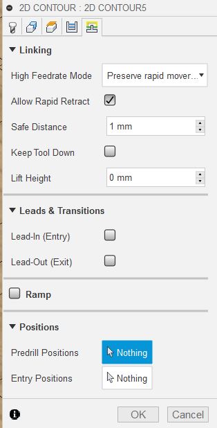
From the final menu disable lead in and lead out options
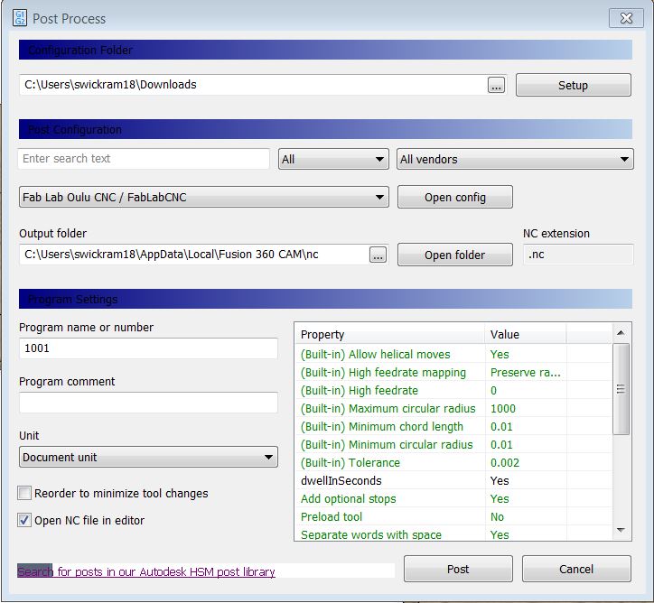
Finally to the export nc file go to post-processing menu by Actions > Post process window. Te provided Post Configuration file by Our Fab Lab was used to translate the Fusion 360 dialect into the dialect that the machine understands. This script can be selected from the settings. After pressing the Post button the nc file will be generated and stored in the output folder
Cutting process using wood router
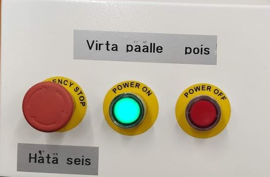
First, open the NC studio software which controls the machine and turn on the wood router.
Then we need to set the machine zero (mechanical origin) by clicking the press All Axes button in window.
Put the board on the machine platform and screw it well.
Then set the X and Y coordinates using the X,Y buttons shown and click left top corner coordinates to make the origin for X and Y.
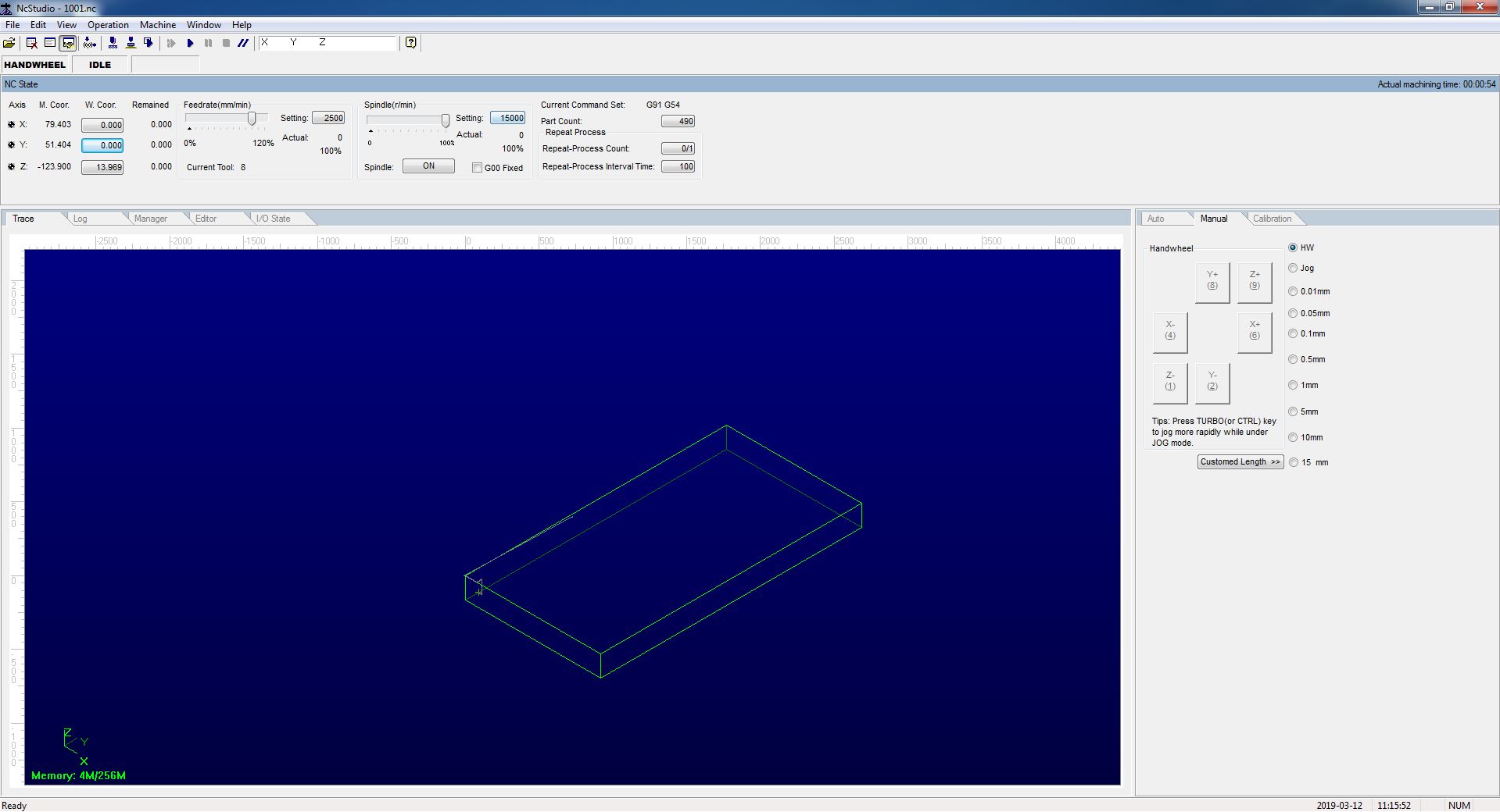
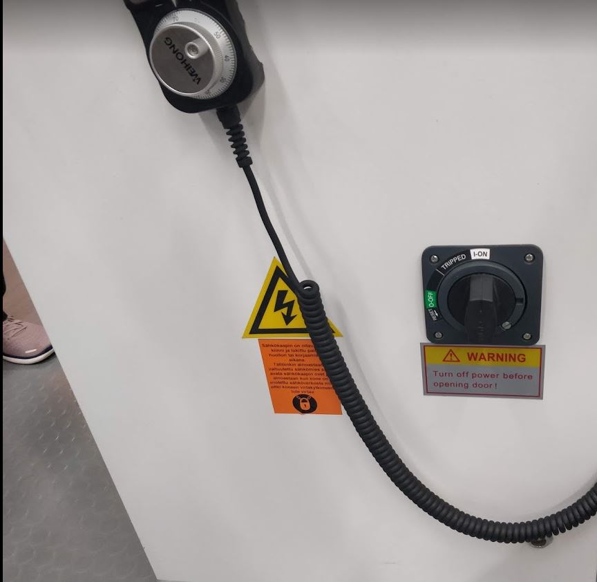
The hand wheel also can be used to move the milling head.
To set the Z origin we can use the auto calibrator. Put the calibrator below the milling bit and from the CNC studio select Operation > Mobile calibrator . Then the z-axis will be calibrated automatically.
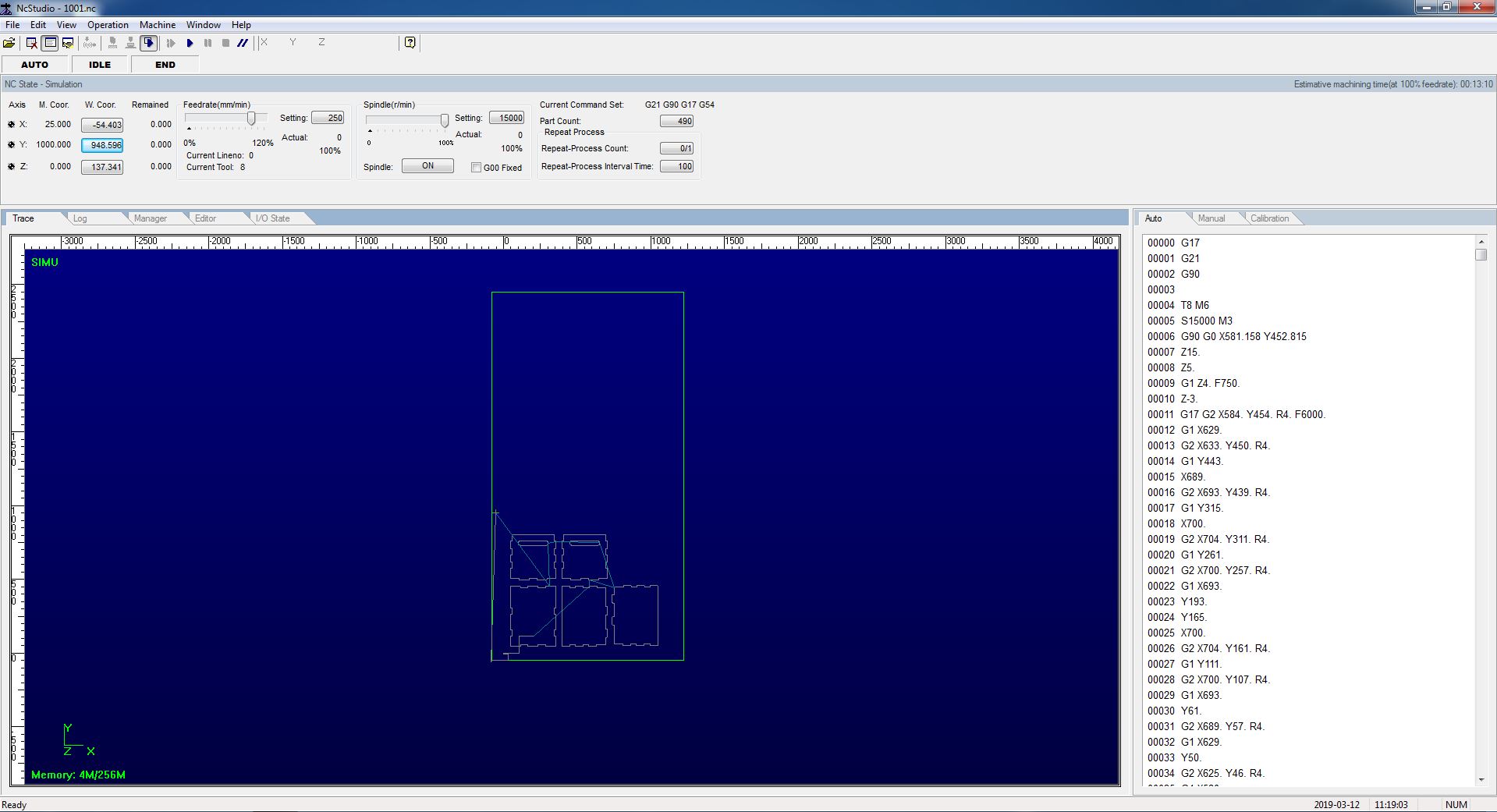
We can simulate the process before cutting the boadrd by pressing the simulation button. Then reduce the feedrate and the spindle speed to around 80%. To start the process, open the NC file (File > Load) and then press the Start process button from the main window.
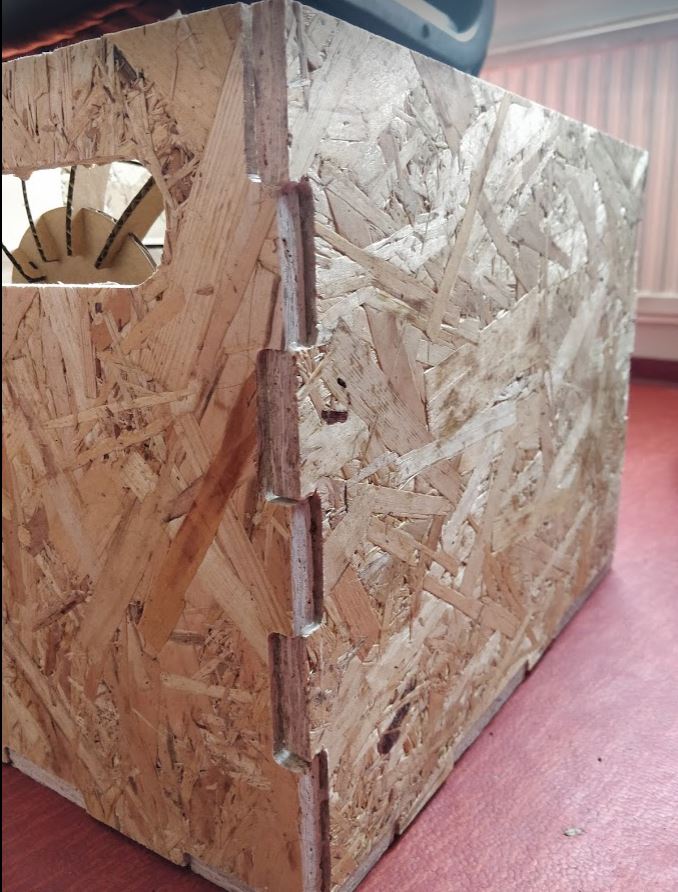
P.S.
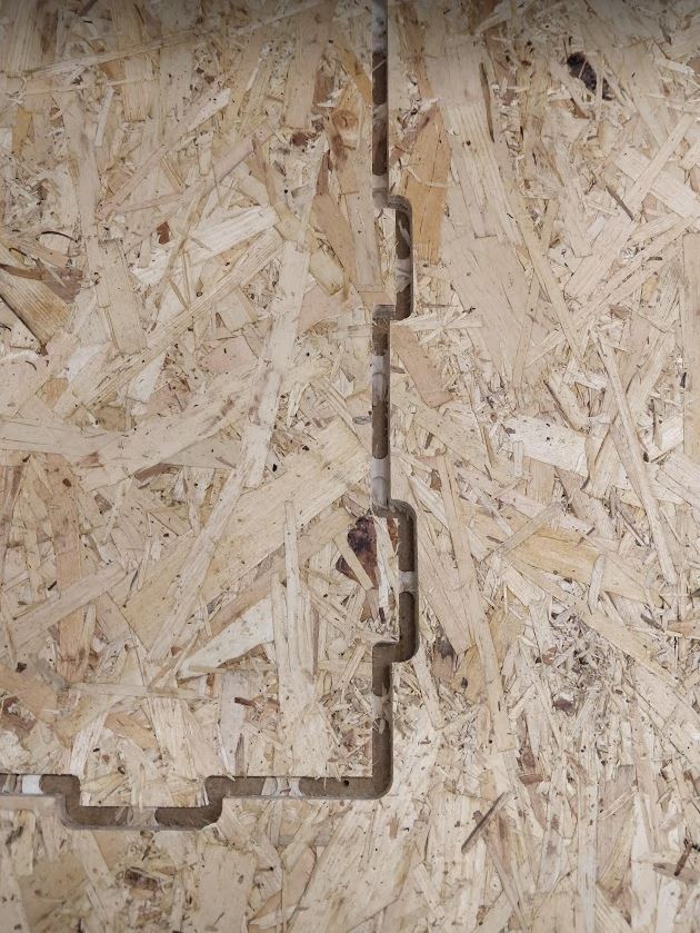
After pointed out by the global evaluator it was noticed that I do not have 'dogbones' in my design.This tutorial was useful for me to get a proper undertanding of dogbones. In my case, the OSB material was flexible enough and that with a little bit of hammering and woodglue the pieces would fit together.
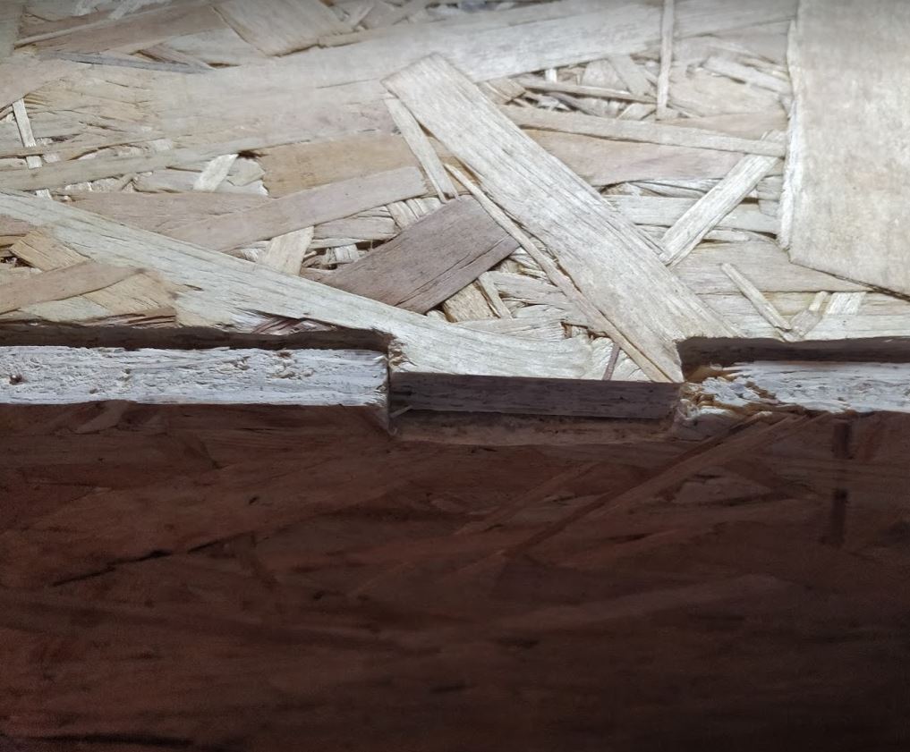
If I were to do the design again I can use the dogbone plugin for fusion to make the dogbones slots. For example, I have created the dogbone for one piece.
After I downloaded the plugin and copied it to the C:\Users\swickram18\AppData\Roaming\Autodesk\Autodesk Fusion 360\API\AddIns
Then After opening the fusion360, I run the dogbone Add-in from the Add-in menu.
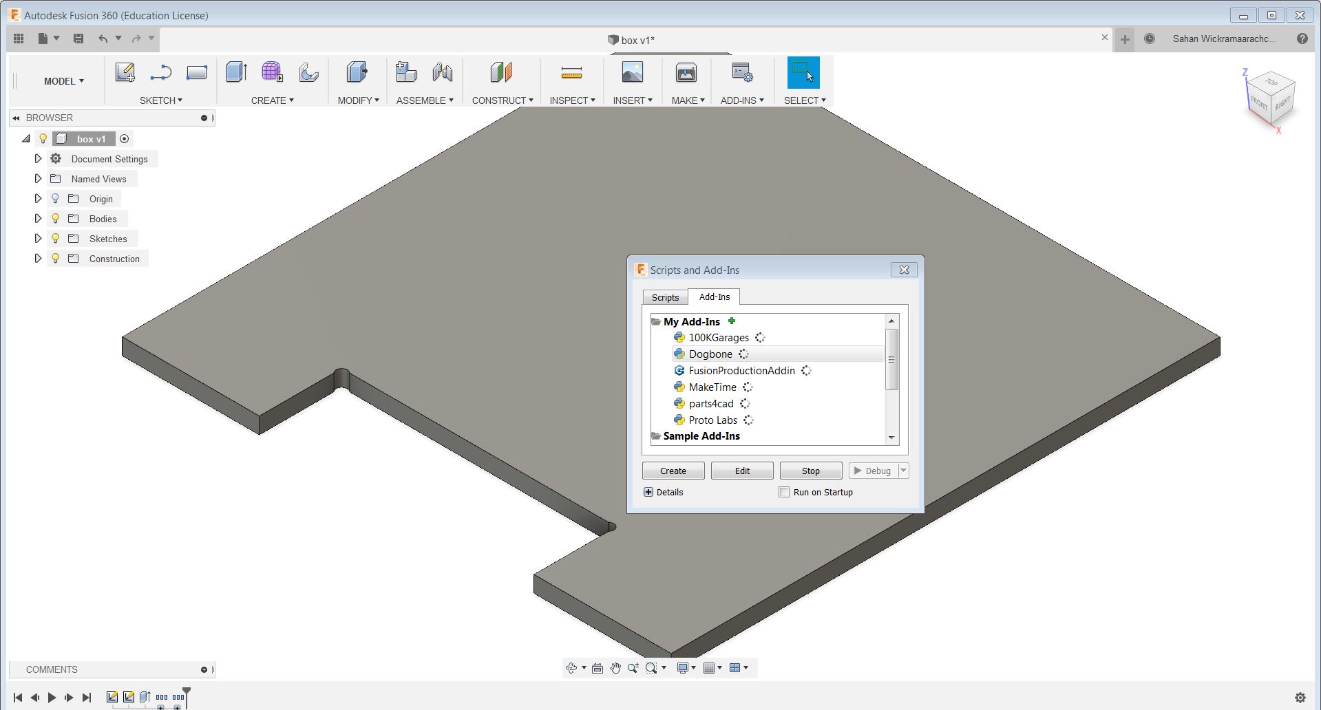
After clicking on the Dogbone Add-in it will open a window .
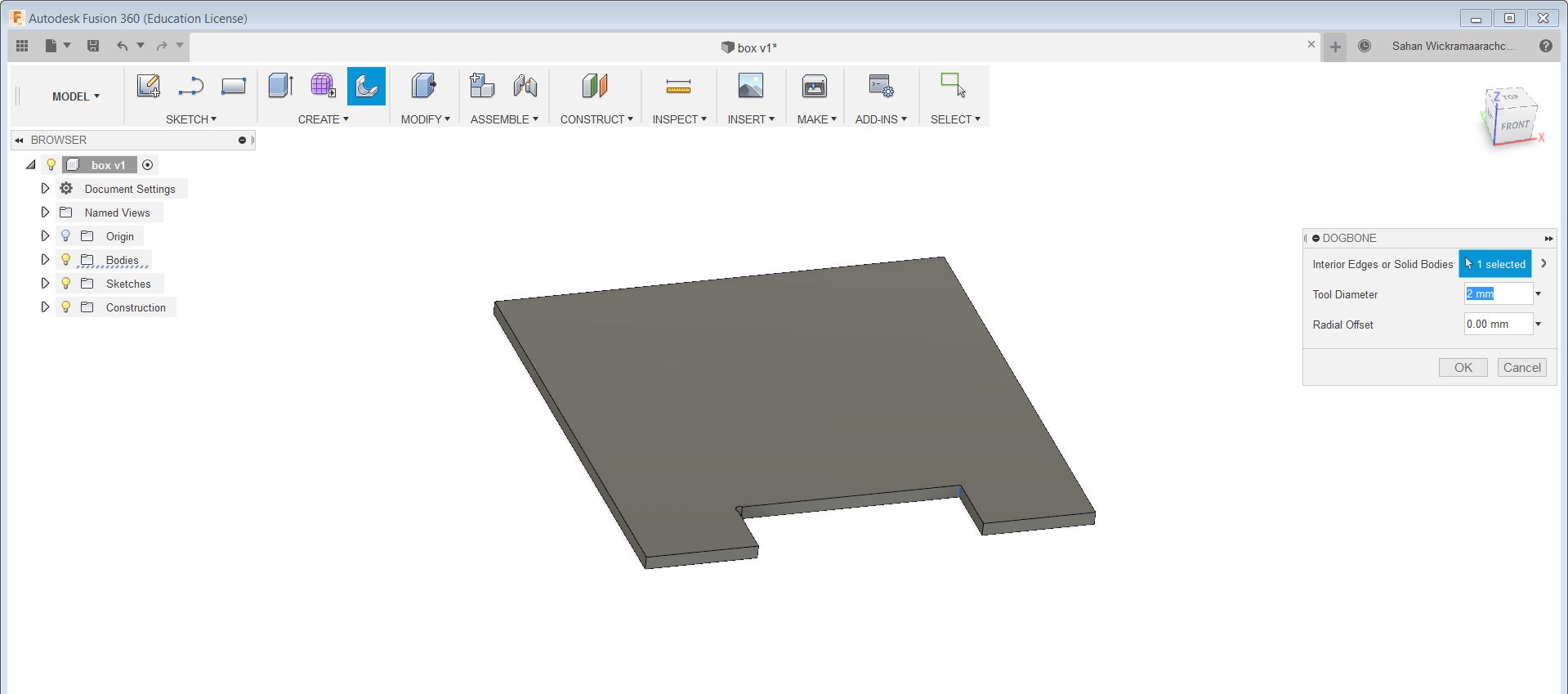
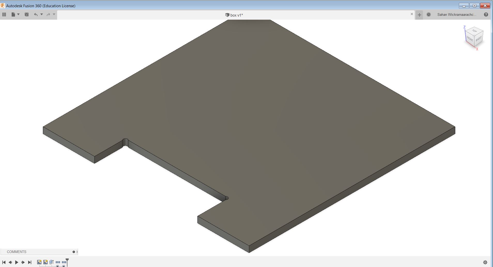
After selecting the edges we want dogbones to be created select the tool diameter and press ok. Then it will automatically create the dogbones.
Models files
Design for the box with setup for cutting
F3D file of the design
STL file for the design