fernando meneses


11_add an output device to a microcontroller board you’ve designed and program it to do something
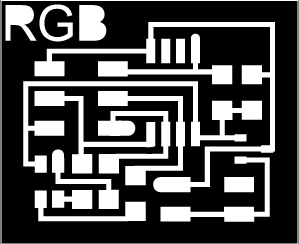
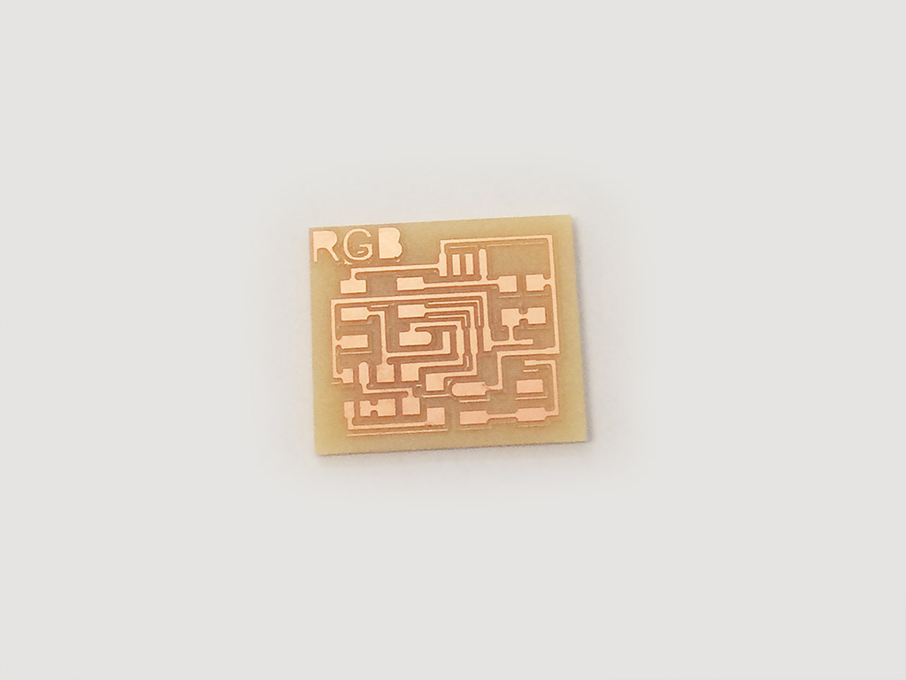
In this activity I will develop a PCB for data entries, chose the RGB, because I think it could be useful for my final project, I’ll start with the PCB of Neil, here an image of the cutting PCB.
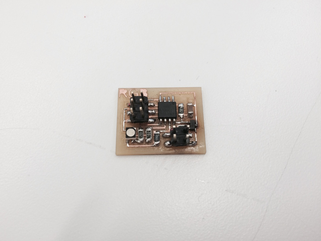
Here another image, now with the components.
To schedule has used for Arduino, thinking particularly of how to control for the final project, here the steps:
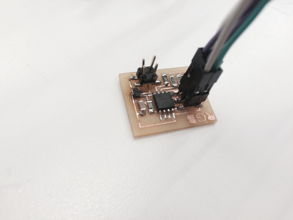
1. Connections, in this case, from the ISP connect the data and power.
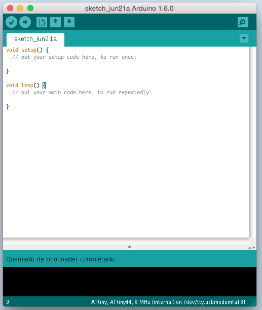
2. Make the bootloader, the steps detailed in the activity “7 embedded programming”, here an image of the bootloader completed.
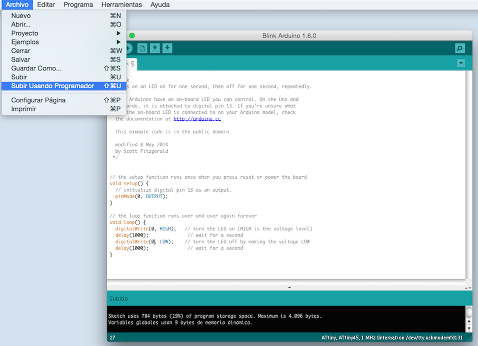
3. In this case to load the code will use the Arduino IDE is simple, just go to the “File” menu and then “charged using programmer” image here:
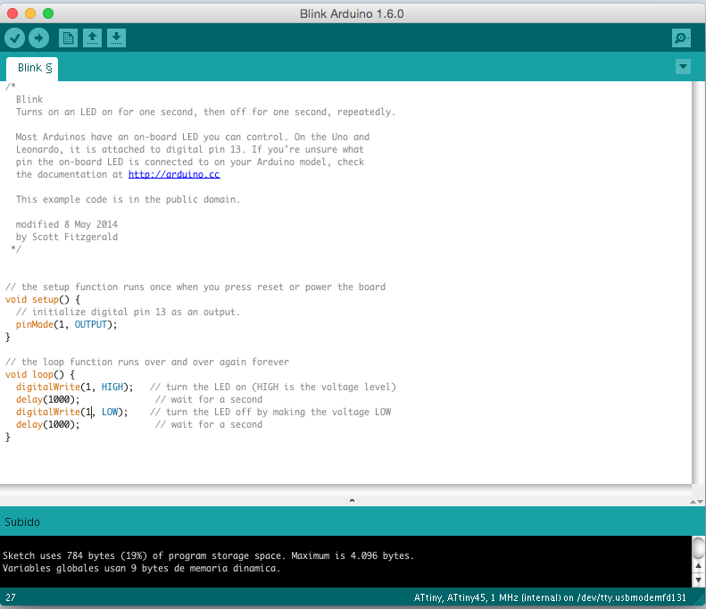
We will use the example of code “Blink” It is important to remember that the outputs that connect to the data in our microprocessor, 0, 1 and 2. For this reason, by sending the code “0” only activates the RGB color “Red”, a video here in red.
By sending “1”, the only active RGB color “green”.
Here a video green.
And to send “2”, the RGB only activates the “blue” color.
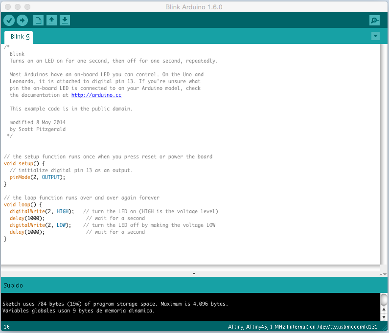
Here is a video in blue.
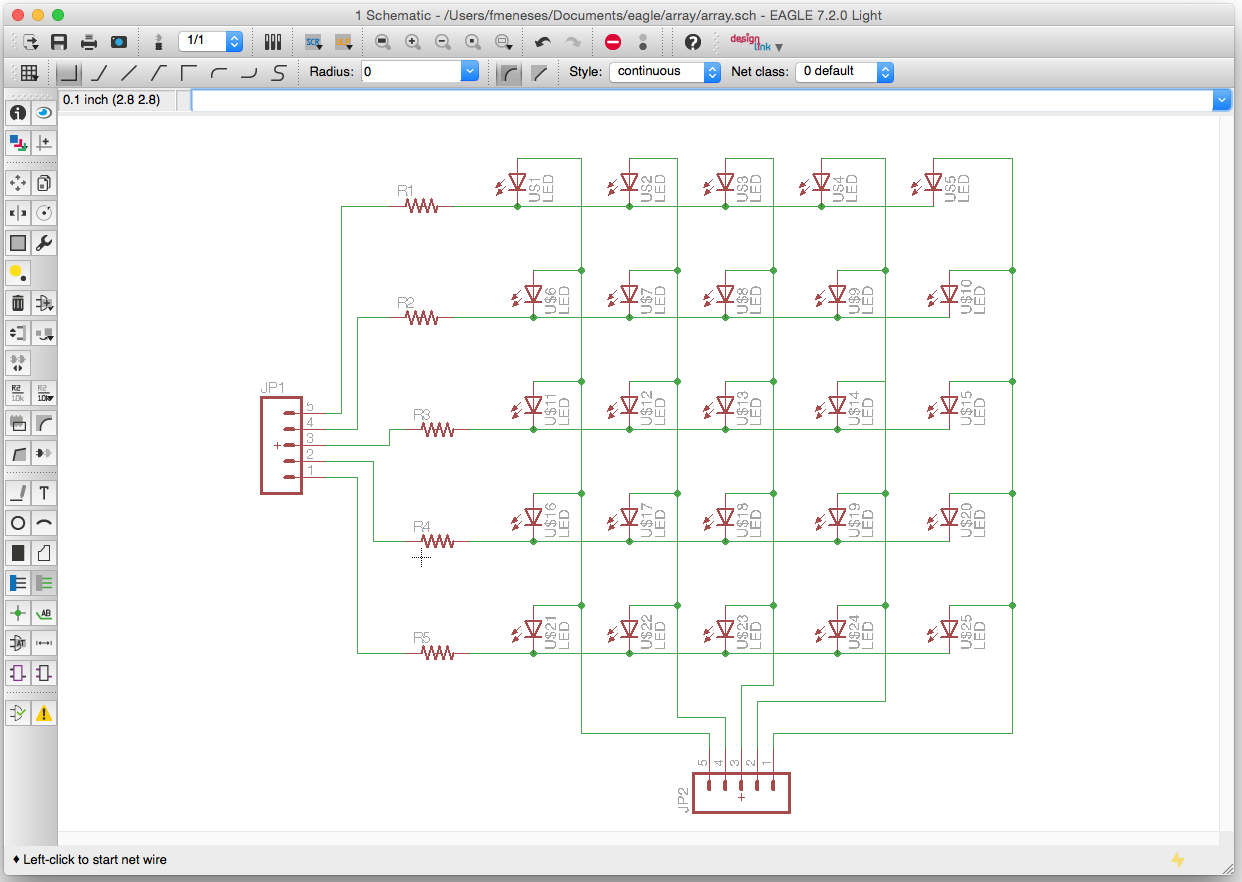
In my case, I do not need color, so that passeth to another example of Neil, now I go to prepare a matrix of LEDs. The idea is to generate numbers from 1 to 12 with a matrix of 5 × 5. Here the diagram in Eagle.
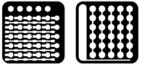
The plan for the final project is to make a PCB to control inputs and outputs, in this case the LED matrix is output, the microcontroller will be in the center plate. PNG cut here.
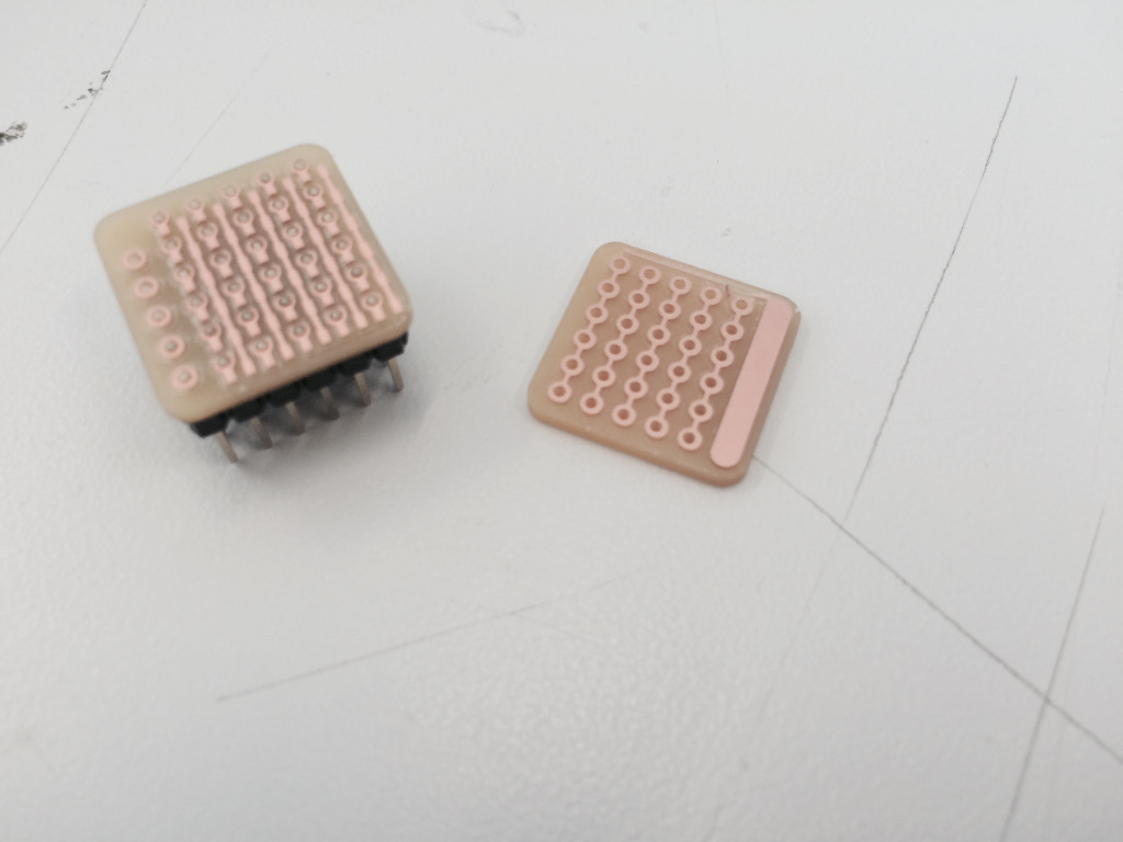
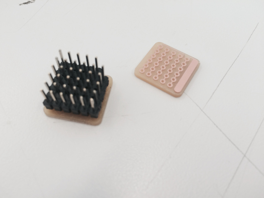
Here the plates ready for cutting and welding.
I will be used to program the IDE of Arduino, sending the data to control the LED matrix of 5 × 5, the code would look like.
- byte matrix[5][5]= {
- {1, 1, 1, 1, 1},
- {1, 1, 1, 1, 1},
- {1, 1, 1, 1, 1},
- {1, 1, 1, 1, 1},
- {1, 1, 1, 1, 1}
- };
- byte anodes[5] = {9,10,11,12,13}; // +pin
- byte cathodes[5] = {3,4,5,6,7}; // -pin
- byte i;
- void setPinTo5V(byte pin)
- {
- pinMode(pin, OUTPUT);
- digitalWrite(pin, HIGH);
- }
- void setPinToGND(byte pin)
- {
- pinMode(pin, OUTPUT);
- digitalWrite(pin, LOW);
- }
- void clearAllPins()
- {
- for(i=0;i<4;i++)
- {
- pinMode(anodes[i], INPUT);
- digitalWrite(anodes[i], LOW);
- pinMode(cathodes[i], INPUT);
- digitalWrite(cathodes[i], LOW);
- }
- }
- void setup()
- {
- }
- void loop()
- {
- for(i=0;i<5;i++)
- {
- clearAllPins();
- if(matrix[0][i]==1)
- setPinTo5V(anodes[0]);
- if(matrix[1][i]==1)
- setPinTo5V(anodes[1]);
- if(matrix[2][i]==1)
- setPinTo5V(anodes[2]);
- if(matrix[3][i]==1)
- setPinTo5V(anodes[3]);
- if(matrix[4][i]==1)
- setPinTo5V(anodes[4]);
- setPinToGND(cathodes[i]);
- delay(1);
- }
- }
And here the first tests.
_conclusion
After receiving the data, the most fun is to send data, in this activity, I learned that the microcontroller allow sending data, each pin becomes a door that sends messages high or low to a physical device, and basically that’s it, but it’s magic.
It is important to remember the microcontroller outputs data at the time of programming, and it is also very important to think that the physical device data is also received and as they are received.
In some code, I learned how to generate the matrix and to define the output pins, and clearly remember that many errors are caused by bad connections, physical or digital.
_files
Eagle-array
png-array
array-code
RGB.ai
RGB.png
videos
_
Original source: http://academy.cba.mit.edu/classes/output_devices/index.html
Contact: fernando.meneses@udem.edu / fernandomeneses@nodolab.com / f / in / g+ / b / v / mx / w