fernando meneses


10_measure something: add a sensor to a microcontroller board that you’ve designed and read it
For this activity, I will try to design a sensor for my final project (the artifact for bacteria).
first part_
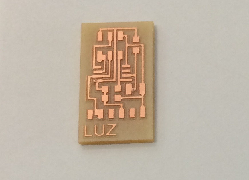
To start with, and not being an expert on the subject, I will begin with activity sensors in the image below the PNG share of the light sensor.

Here the PCB-luz:
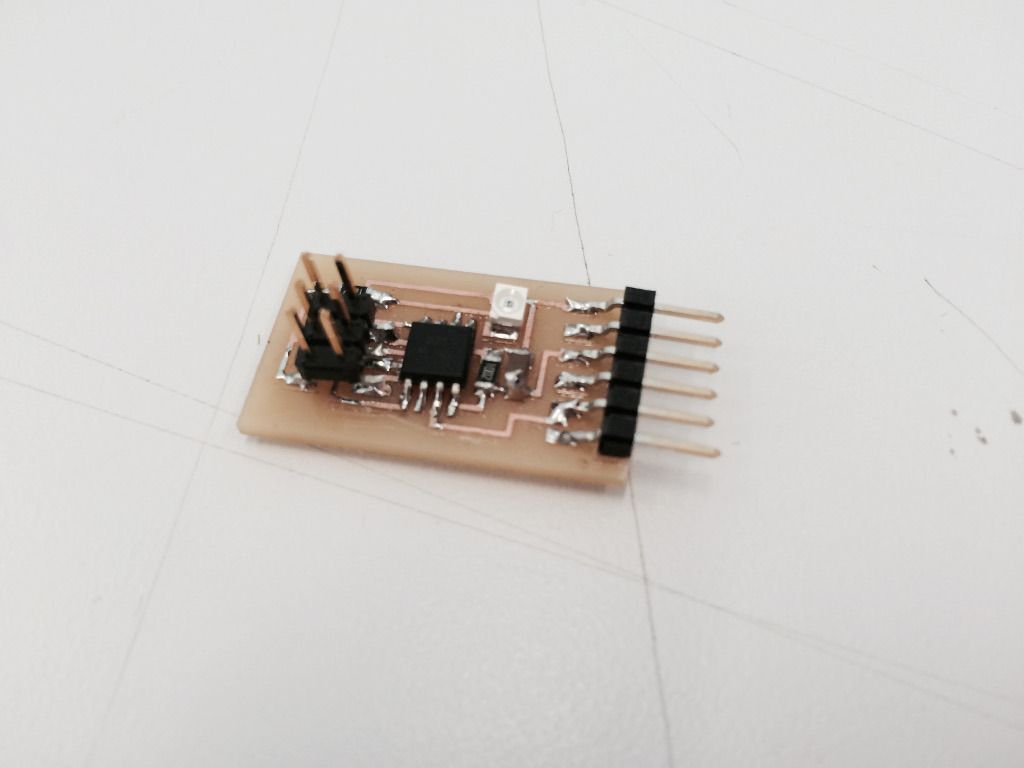
Here the sensor components:
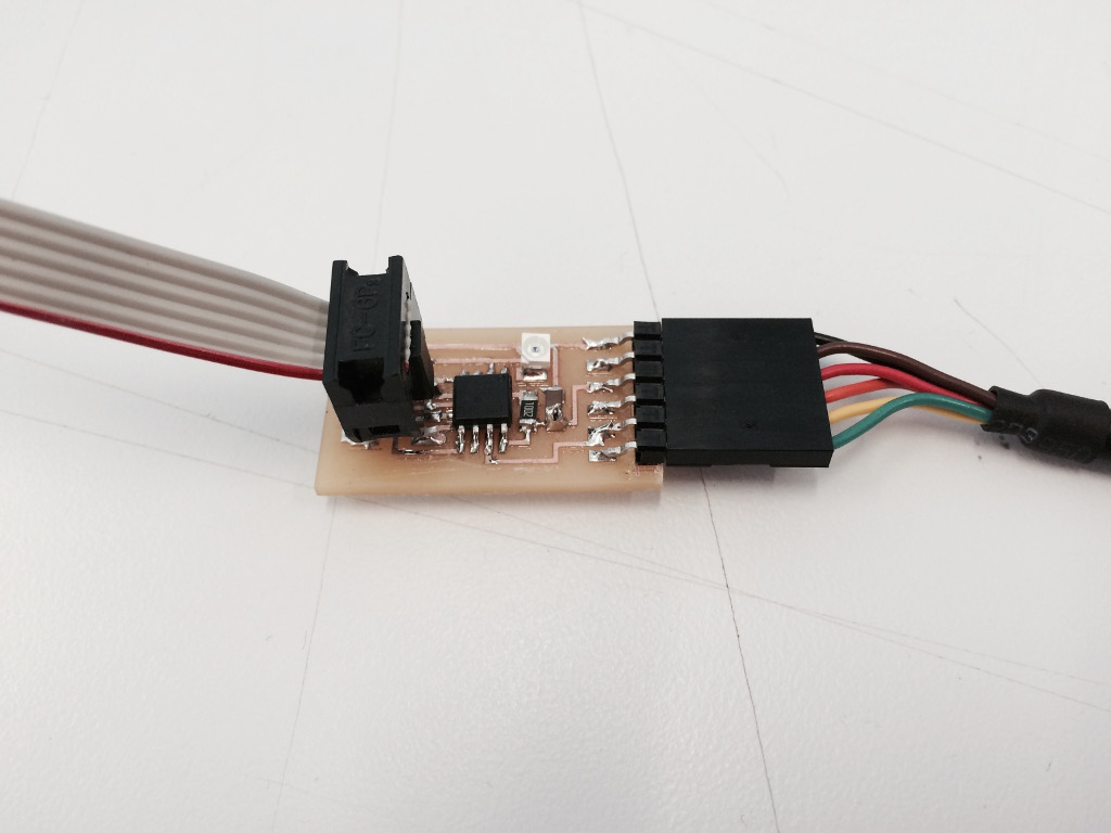
We will use the ISP for the data and the FTDI for energy.
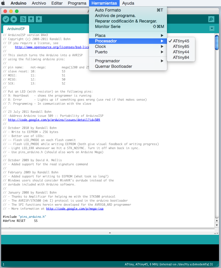
To program the bootloader (see more 7 embedded programming)
We select our ATtiny microcontrollers..
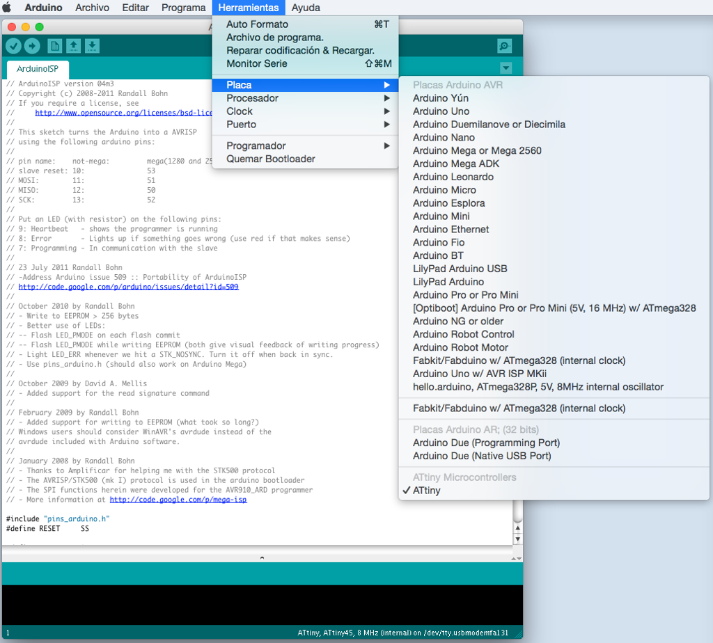
Select the ATtiny45.
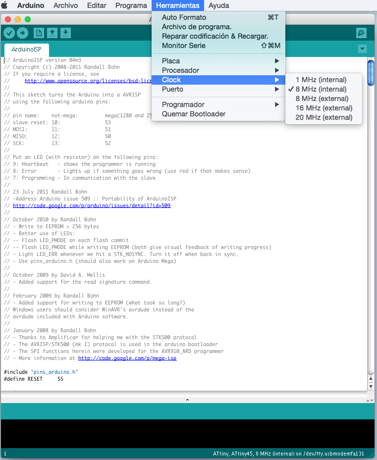
Select the clock.
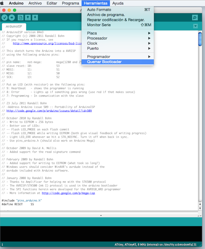
And now, launch bootloader burned.
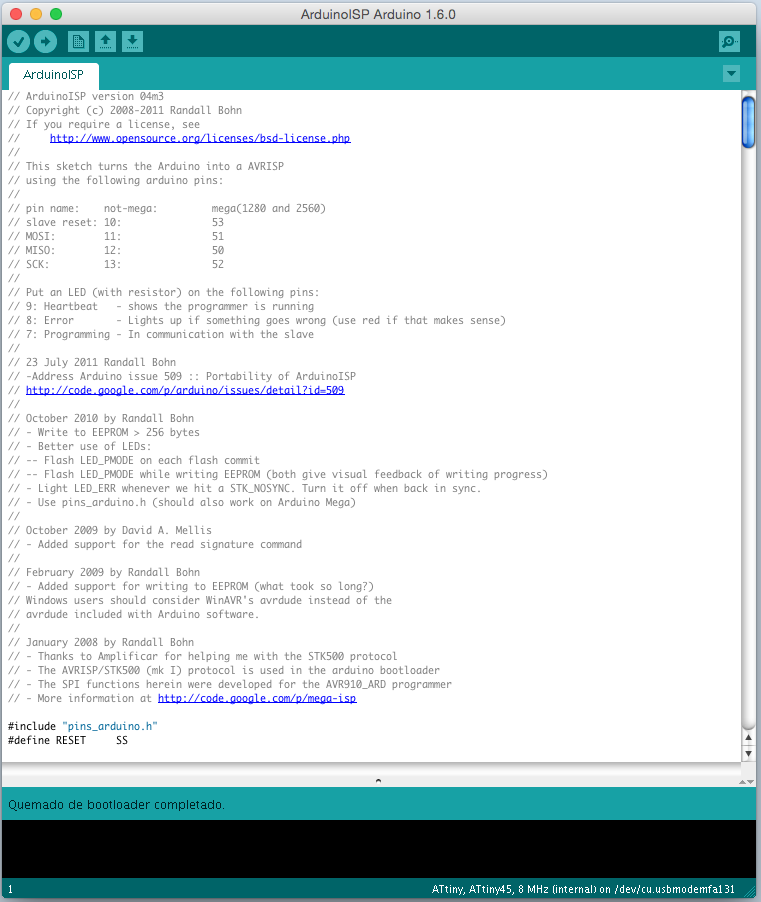
Burning I bootloader completed.
To program will use the example of “AnalogReadSerial”.
- void setup() {
- Serial.begin(9600);
- }
- void loop() {
- int sensorValue = analogRead("pin");
- Serial.println(sensorValue);
- delay(1);
- }
To open the serial port, it opens in Tools / serial.
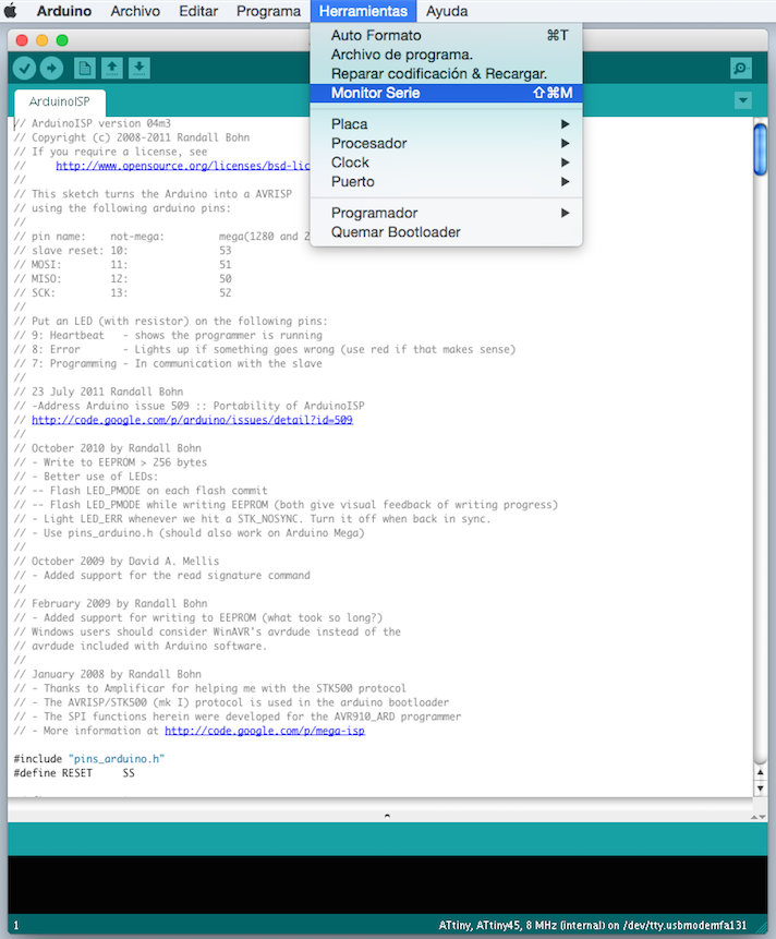
It can also be opened from menu, in the serial monitor icon.
Here is a video to read the sensor data.
second part_
The next step we made in our laboratory was looking for the largest possible number of sensors in the I share image sensors are:
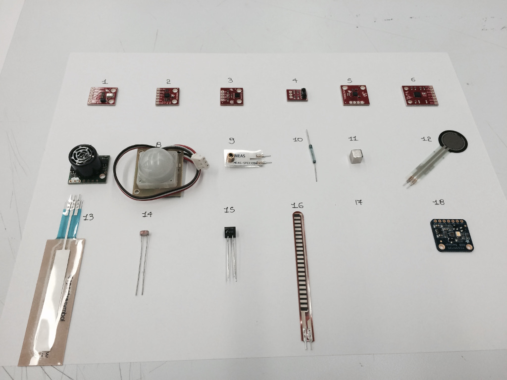
1- Height Sensor/Pressure – MPL3115A2
2 – Accelerometer, three Axis – MMA8452Q
3 – Humidity Sensor HTU21D
4 – IR Receiver
5 – Magnetometer, three Axis – HMC5883L
6 – Gyroscope with digital outputs, three axes ITG-3200
7 – Ultrasonic Rangefinder – Maxbotix LV-EZ1
8 – PIR Motion Sensor
9 – Large Piezo Vibration Sensor
10, Reed Switch
11- Imam Square 0.25 ”
12 – Resistance Force-sensitive 0.5 ”
13 – SoftPot
14 – Cell Fotoeléctricia
15 – Optical Detector / Phototransistor
16 – Flexible Sensor
17 – Sound Sensor
18 – Color Sensor
As a starting point I will use the color sensor TCS34725 shared by Adafruit:
https://github.com/adafruit/Adafruit_TCS34725
Here an image sensor:
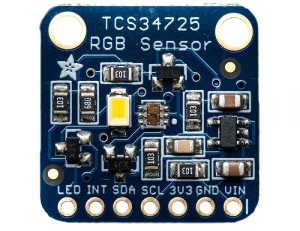
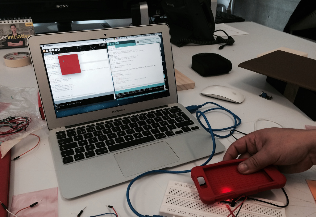
To test the operation of the sensor, I used an Arduino Mega and the original sensor Adafruit, here we see sensor operation:
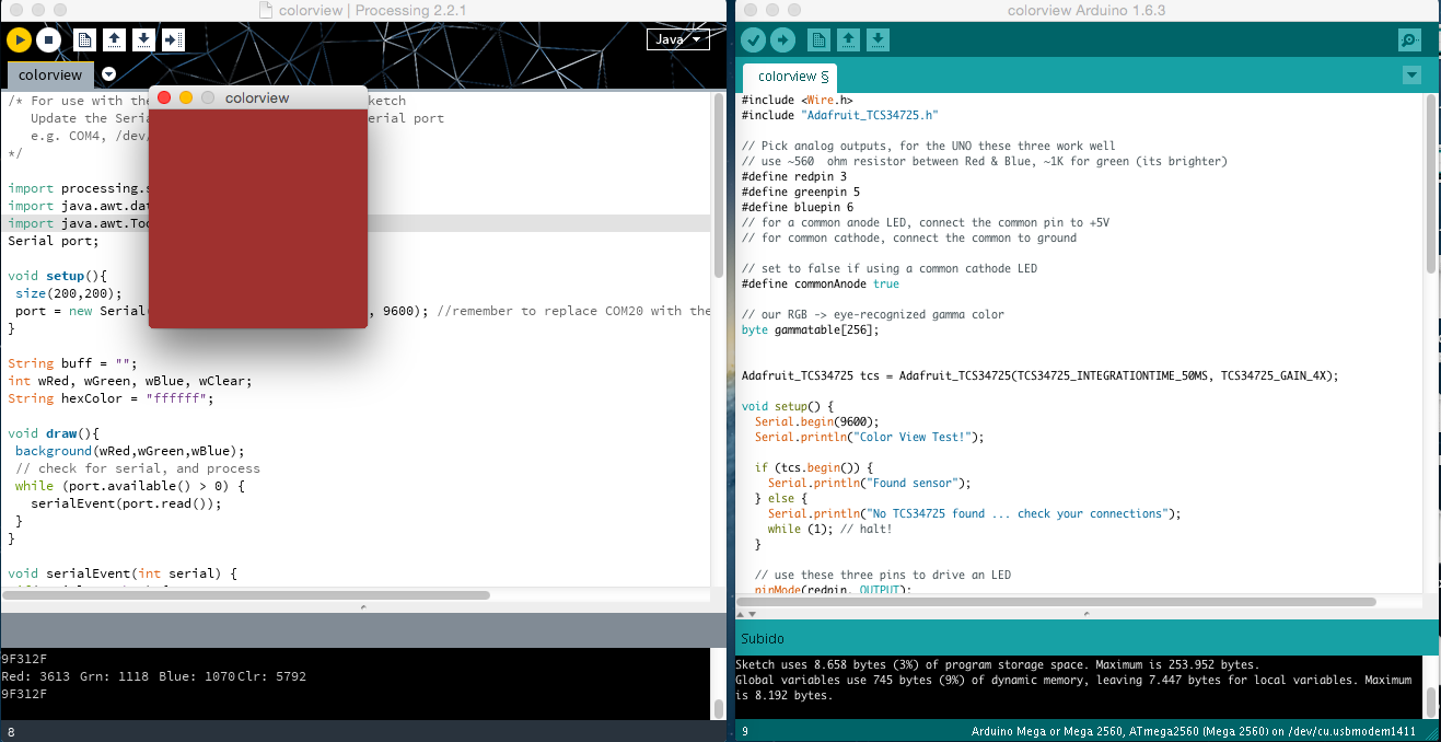
Here is the sample code to control the sensor from the Arduino:
- #include
- #include "Adafruit_TCS34725.h"
- #define redpin 3
- #define greenpin 5
- #define bluepin 6
- #define commonAnode true
- byte gammatable[256];
- Adafruit_TCS34725 tcs = Adafruit_TCS34725(TCS34725_INTEGRATIONTIME_50MS, TCS34725_GAIN_4X);
- void setup() {
- Serial.begin(9600);
- Serial.println("Color View Test!");
- if (tcs.begin()) {
- Serial.println("Found sensor");
- } else {
- Serial.println("No TCS34725 found ... check your connections");
- while (1); // halt!
- }
- pinMode(redpin, OUTPUT);
- pinMode(greenpin, OUTPUT);
- pinMode(bluepin, OUTPUT);
- for (int i=0; i<256; i++) {
- float x = i;
- x /= 255;
- x = pow(x, 2.5);
- x *= 255;
- if (commonAnode) {
- gammatable[i] = 255 - x;
- } else {
- gammatable[i] = x;
- }
- }
- }
- void loop() {
- uint16_t clear, red, green, blue;
- tcs.setInterrupt(false);
- delay(60);
- tcs.getRawData(&red, &green, &blue, &clear);
- tcs.setInterrupt(true);
- Serial.print("C:\t"); Serial.print(clear);
- Serial.print("\tR:\t"); Serial.print(red);
- Serial.print("\tG:\t"); Serial.print(green);
- Serial.print("\tB:\t"); Serial.print(blue);
- uint32_t sum = clear;
- float r, g, b;
- r = red; r /= sum;
- g = green; g /= sum;
- b = blue; b /= sum;
- r *= 256; g *= 256; b *= 256;
- Serial.print("\t");
- Serial.print((int)r, HEX); Serial.print((int)g, HEX); Serial.print((int)b, HEX);
- Serial.println();
- analogWrite(redpin, gammatable[(int)r]);
- analogWrite(greenpin, gammatable[(int)g]);
- analogWrite(bluepin, gammatable[(int)b]);
- }
and here the code for the interface in Processing:
- import processing.serial.*;
- import java.awt.datatransfer.*;
- import java.awt.Toolkit;
- Serial port;
- void setup(){
- size(200,200);
- port = new Serial(this, "/dev/cu.usbmodem1411", 9600);
- }
- String buff = "";
- int wRed, wGreen, wBlue, wClear;
- String hexColor = "ffffff";
- void draw(){
- background(wRed,wGreen,wBlue);
- while (port.available() > 0) {
- serialEvent(port.read());
- }
- }
- void serialEvent(int serial) {
- if(serial != '\n') {
- buff += char(serial);
- } else {
- int cRed = buff.indexOf("R");
- int cGreen = buff.indexOf("G");
- int cBlue = buff.indexOf("B");
- int clear = buff.indexOf("C");
- if(clear >=0){
- String val = buff.substring(clear+3);
- val = val.split("\t")[0];
- wClear = Integer.parseInt(val.trim());
- } else { return; }
- if(cRed >=0){
- String val = buff.substring(cRed+3);
- val = val.split("\t")[0];
- wRed = Integer.parseInt(val.trim());
- } else { return; }
- if(cGreen >=0) {
- String val = buff.substring(cGreen+3);
- val = val.split("\t")[0];
- wGreen = Integer.parseInt(val.trim());
- } else { return; }
- if(cBlue >=0) {
- String val = buff.substring(cBlue+3);
- val = val.split("\t")[0];
- wBlue = Integer.parseInt(val.trim());
- } else { return; }
- print("Red: "); print(wRed);
- print("\tGrn: "); print(wGreen);
- print("\tBlue: "); print(wBlue);
- print("\tClr: "); println(wClear);
- wRed *= 255; wRed /= wClear;
- wGreen *= 255; wGreen /= wClear;
- wBlue *= 255; wBlue /= wClear;
- hexColor = hex(color(wRed, wGreen, wBlue), 6);
- println(hexColor);
- buff = "";
- }
- }
You need to be a little careful with external light, but the sensor works perfectly.
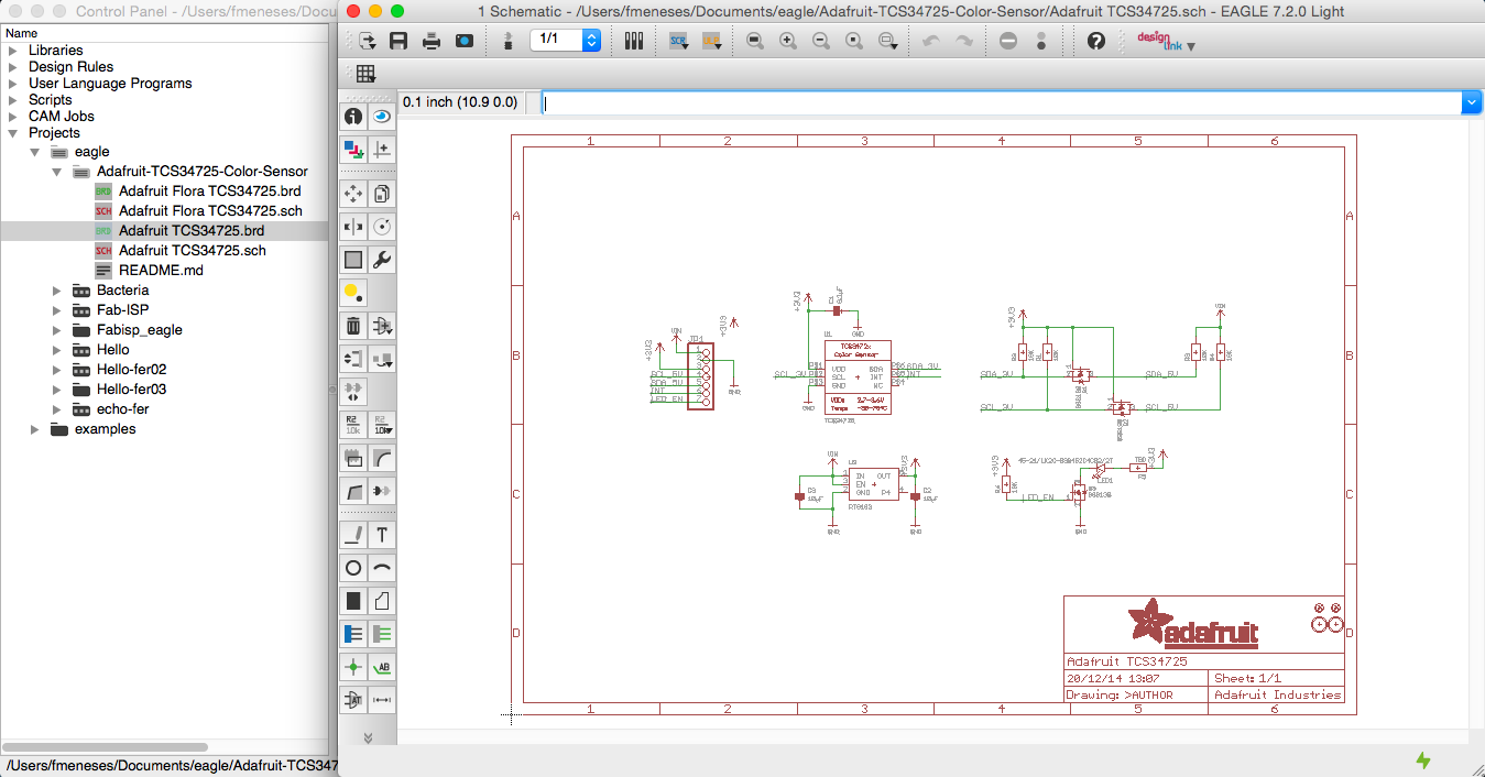
The plate was designed by Adafruit Industries. Creative Commons Attribution license, can download the library here:
https://github.com/adafruit/Adafruit-Eagle-Library
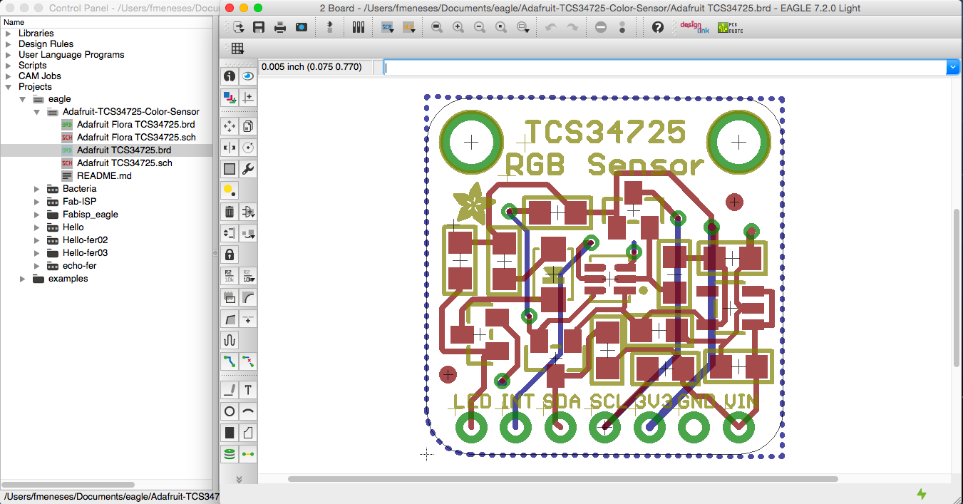
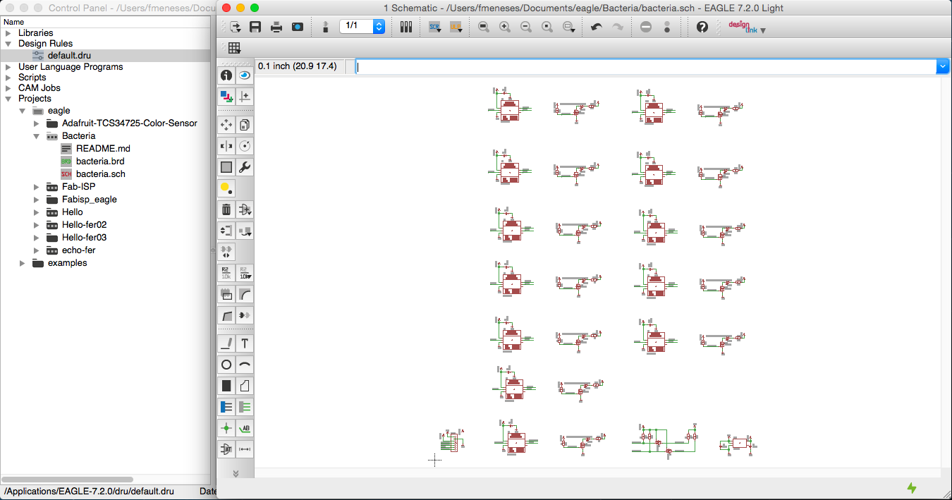
And here we see TCS34725 Eagle files:
After this, I have designed a PCB with sensors for bacteria recognizer.
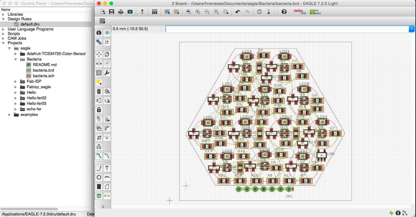
After reviewing the cost of the device with 12 sensors, and thinking it was an inexpensive device, it was decided to make a simple PCB in one sensor, for now embark on the light sensor Adafruit, but in the Future development must include a sensor device of a color, so leave this here for future reference.
At the moment I am presenting in the python code for TCS34725:
https://github.com/adafruit/Adafruit-Raspberry-Pi-Python-Code/tree/master/Adafruit_TCS34725
- +#!/usr/bin/python
- +
- +import time
- +from Adafruit_I2C import Adafruit_I2C
- +
- +# ===========================================================================
- +# TCS3472 Class
- +# ===========================================================================
- +
- +
- +class TCS34725:
- + i2c = None
- +
- + __TCS34725_ADDRESS = 0x29
- + __TCS34725_ID = 0x12 # 0x44 = TCS34721/TCS34725, 0x4D = TCS34723/TCS34727
- +
- + __TCS34725_COMMAND_BIT = 0x80
- +
- + __TCS34725_ENABLE = 0x00
- + __TCS34725_ENABLE_AIEN = 0x10 # RGBC Interrupt Enable
- + __TCS34725_ENABLE_WEN = 0x08 # Wait enable - Writing 1 activates the wait timer
- + __TCS34725_ENABLE_AEN = 0x02 # RGBC Enable - Writing 1 actives the ADC, 0 disables it
- + __TCS34725_ENABLE_PON = 0x01 # Power on - Writing 1 activates the internal oscillator, 0 disables it
- + __TCS34725_ATIME = 0x01 # Integration time
- + __TCS34725_WTIME = 0x03 # Wait time (if TCS34725_ENABLE_WEN is asserted)
- + __TCS34725_WTIME_2_4MS = 0xFF # WLONG0 = 2.4ms WLONG1 = 0.029s
- + __TCS34725_WTIME_204MS = 0xAB # WLONG0 = 204ms WLONG1 = 2.45s
- + __TCS34725_WTIME_614MS = 0x00 # WLONG0 = 614ms WLONG1 = 7.4s
- + __TCS34725_AILTL = 0x04 # Clear channel lower interrupt threshold
- + __TCS34725_AILTH = 0x05
- + __TCS34725_AIHTL = 0x06 # Clear channel upper interrupt threshold
- + __TCS34725_AIHTH = 0x07
- + __TCS34725_PERS = 0x0C # Persistence register - basic SW filtering mechanism for interrupts
- + __TCS34725_PERS_NONE = 0b0000 # Every RGBC cycle generates an interrupt
- + __TCS34725_PERS_1_CYCLE = 0b0001 # 1 clean channel value outside threshold range generates an interrupt
- + __TCS34725_PERS_2_CYCLE = 0b0010 # 2 clean channel values outside threshold range generates an interrupt
- + __TCS34725_PERS_3_CYCLE = 0b0011 # 3 clean channel values outside threshold range generates an interrupt
- + __TCS34725_PERS_5_CYCLE = 0b0100 # 5 clean channel values outside threshold range generates an interrupt
- + __TCS34725_PERS_10_CYCLE = 0b0101 # 10 clean channel values outside threshold range generates an interrupt
- + __TCS34725_PERS_15_CYCLE = 0b0110 # 15 clean channel values outside threshold range generates an interrupt
- + __TCS34725_PERS_20_CYCLE = 0b0111 # 20 clean channel values outside threshold range generates an interrupt
- + __TCS34725_PERS_25_CYCLE = 0b1000 # 25 clean channel values outside threshold range generates an interrupt
- + __TCS34725_PERS_30_CYCLE = 0b1001 # 30 clean channel values outside threshold range generates an interrupt
- + __TCS34725_PERS_35_CYCLE = 0b1010 # 35 clean channel values outside threshold range generates an interrupt
- + __TCS34725_PERS_40_CYCLE = 0b1011 # 40 clean channel values outside threshold range generates an interrupt
- + __TCS34725_PERS_45_CYCLE = 0b1100 # 45 clean channel values outside threshold range generates an interrupt
- + __TCS34725_PERS_50_CYCLE = 0b1101 # 50 clean channel values outside threshold range generates an interrupt
- + __TCS34725_PERS_55_CYCLE = 0b1110 # 55 clean channel values outside threshold range generates an interrupt
- + __TCS34725_PERS_60_CYCLE = 0b1111 # 60 clean channel values outside threshold range generates an interrupt
- + __TCS34725_CONFIG = 0x0D
- + __TCS34725_CONFIG_WLONG = 0x02 # Choose between short and long (12x) wait times via TCS34725_WTIME
- + __TCS34725_CONTROL = 0x0F # Set the gain level for the sensor
- + __TCS34725_ID = 0x12 # 0x44 = TCS34721/TCS34725, 0x4D = TCS34723/TCS34727
- + __TCS34725_STATUS = 0x13
- + __TCS34725_STATUS_AINT = 0x10 # RGBC Clean channel interrupt
- + __TCS34725_STATUS_AVALID = 0x01 # Indicates that the RGBC channels have completed an integration cycle
- +
- + __TCS34725_CDATAL = 0x14 # Clear channel data
- + __TCS34725_CDATAH = 0x15
- + __TCS34725_RDATAL = 0x16 # Red channel data
- + __TCS34725_RDATAH = 0x17
- + __TCS34725_GDATAL = 0x18 # Green channel data
- + __TCS34725_GDATAH = 0x19
- + __TCS34725_BDATAL = 0x1A # Blue channel data
- + __TCS34725_BDATAH = 0x1B
- +
- + __TCS34725_INTEGRATIONTIME_2_4MS = 0xFF # 2.4ms - 1 cycle - Max Count: 1024
- + __TCS34725_INTEGRATIONTIME_24MS = 0xF6 # 24ms - 10 cycles - Max Count: 10240
- + __TCS34725_INTEGRATIONTIME_50MS = 0xEB # 50ms - 20 cycles - Max Count: 20480
- + __TCS34725_INTEGRATIONTIME_101MS = 0xD5 # 101ms - 42 cycles - Max Count: 43008
- + __TCS34725_INTEGRATIONTIME_154MS = 0xC0 # 154ms - 64 cycles - Max Count: 65535
- + __TCS34725_INTEGRATIONTIME_700MS = 0x00 # 700ms - 256 cycles - Max Count: 65535
- +
- + __TCS34725_GAIN_1X = 0x00 # No gain
- + __TCS34725_GAIN_4X = 0x01 # 2x gain
- + __TCS34725_GAIN_16X = 0x02 # 16x gain
- + __TCS34725_GAIN_60X = 0x03 # 60x gain
- +
- + __integrationTimeDelay = {
- + 0xFF: 0.0024, # 2.4ms - 1 cycle - Max Count: 1024
- + 0xF6: 0.024, # 24ms - 10 cycles - Max Count: 10240
- + 0xEB: 0.050, # 50ms - 20 cycles - Max Count: 20480
- + 0xD5: 0.101, # 101ms - 42 cycles - Max Count: 43008
- + 0xC0: 0.154, # 154ms - 64 cycles - Max Count: 65535
- + 0x00: 0.700 # 700ms - 256 cycles - Max Count: 65535
- + }
- +
- + # Private Methods
- + def __readU8(self, reg):
- + return self.i2c.readU8(self.__TCS34725_COMMAND_BIT | reg)
- +
- + def __readU16Rev(self, reg):
- + return self.i2c.readU16Rev(self.__TCS34725_COMMAND_BIT | reg)
- +
- + def __write8(self, reg, value):
- + self.i2c.write8(self.__TCS34725_COMMAND_BIT | reg, value & 0xff)
- +
- + # Constructor
- + def __init__(self, address=0x29, debug=False, integrationTime=0xFF, gain=0x01):
- + self.i2c = Adafruit_I2C(address)
- +
- + self.address = address
- + self.debug = debug
- + self.integrationTime = integrationTime
- + self.initialize(integrationTime, gain)
- +
- + def initialize(self, integrationTime, gain):
- + "Initializes I2C and configures the sensor (call this function before \
- + doing anything else)"
- + # Make sure we're actually connected
- + result = self.__readU8(self.__TCS34725_ID)
- + if (result != 0x44):
- + return -1
- +
- + # Set default integration time and gain
- + self.setIntegrationTime(integrationTime)
- + self.setGain(gain)
- +
- + # Note: by default, the device is in power down mode on bootup
- + self.enable()
- +
- + def enable(self):
- + self.__write8(self.__TCS34725_ENABLE, self.__TCS34725_ENABLE_PON)
- + time.sleep(0.01)
- + self.__write8(self.__TCS34725_ENABLE, (self.__TCS34725_ENABLE_PON | self.__TCS34725_ENABLE_AEN))
- +
- + def disable(self):
- + reg = 0
- + reg = self.__readU8(self.__TCS34725_ENABLE)
- + self.__write8(self.__TCS34725_ENABLE, (reg & ~(self.__TCS34725_ENABLE_PON | self.__TCS34725_ENABLE_AEN)))
- +
- + def setIntegrationTime(self, integrationTime):
- + "Sets the integration time for the TC34725"
- + self.integrationTime = integrationTime
- +
- + self.__write8(self.__TCS34725_ATIME, integrationTime)
- +
- + def getIntegrationTime(self):
- + return self.__readU8(self.__TCS34725_ATIME)
- +
- + def setGain(self, gain):
- + "Adjusts the gain on the TCS34725 (adjusts the sensitivity to light)"
- + self.__write8(self.__TCS34725_CONTROL, gain)
- +
- + def getGain(self):
- + return self.__readU8(self.__TCS34725_CONTROL)
- +
- + def getRawData(self):
- + "Reads the raw red, green, blue and clear channel values"
- +
- + color = {}
- +
- + color["r"] = self.__readU16Rev(self.__TCS34725_RDATAL)
- + color["b"] = self.__readU16Rev(self.__TCS34725_BDATAL)
- + color["g"] = self.__readU16Rev(self.__TCS34725_GDATAL)
- + color["c"] = self.__readU16Rev(self.__TCS34725_CDATAL)
- +
- + # Set a delay for the integration time
- + delay = self.__integrationTimeDelay.get(self.integrationTime)
- + time.sleep(delay)
- +
- + return color
- +
- + def setInterrupt(self, int):
- + r = self.__readU8(self.__TCS34725_ENABLE)
- +
- + if (int):
- + r |= self.__TCS34725_ENABLE_AIEN
- + else:
- + r &= ~self.__TCS34725_ENABLE_AIEN
- +
- + self.__write8(self.__TCS34725_ENABLE, r)
- +
- + def clearInterrupt(self):
- + self.i2c.write8(0x66 & 0xff)
- +
- + def setIntLimits(self, low, high):
- + self.i2c.write8(0x04, low & 0xFF)
- + self.i2c.write8(0x05, low >> 8)
- + self.i2c.write8(0x06, high & 0xFF)
- + self.i2c.write8(0x07, high >> 8)
- +
- + #Static Utility Methods
- + @staticmethod
- + def calculateColorTemperature(rgb):
- + "Converts the raw R/G/B values to color temperature in degrees Kelvin"
- +
- + if not isinstance(rgb, dict):
- + raise ValueError('calculateColorTemperature expects dict as parameter')
- +
- + # 1. Map RGB values to their XYZ counterparts.
- + # Based on 6500K fluorescent, 3000K fluorescent
- + # and 60W incandescent values for a wide range.
- + # Note: Y = Illuminance or lux
- + X = (-0.14282 * rgb['r']) + (1.54924 * rgb['g']) + (-0.95641 * rgb['b'])
- + Y = (-0.32466 * rgb['r']) + (1.57837 * rgb['g']) + (-0.73191 * rgb['b'])
- + Z = (-0.68202 * rgb['r']) + (0.77073 * rgb['g']) + ( 0.56332 * rgb['b'])
- +
- + # 2. Calculate the chromaticity co-ordinates
- + xc = (X) / (X + Y + Z)
- + yc = (Y) / (X + Y + Z)
- +
- + # 3. Use McCamy's formula to determine the CCT
- + n = (xc - 0.3320) / (0.1858 - yc)
- +
- + # Calculate the final CCT
- + cct = (449.0 * (n ** 3.0)) + (3525.0 *(n ** 2.0)) + (6823.3 * n) + 5520.33
- +
- + return int(cct)
- +
- + @staticmethod
- + def calculateLux(rgb):
- + "Converts the raw R/G/B values to color temperature in degrees Kelvin"
- +
- + if not isinstance(rgb, dict):
- + raise ValueError('calculateLux expects dict as parameter')
- +
- + illuminance = (-0.32466 * rgb['r']) + (1.57837 * rgb['g']) + (-0.73191 * rgb['b'])
- +
- + return int(illuminance)
_conclusion
Receive data from the real world, is wonderful, this is one of the most powerful parties to do just about anything in particular, I learned that there are a large number of sensors, I also learned that there is a serial port. In this activity explore the input signal from the Arduino.
_files
luz.png
luz.ai
TCS34725.sch
TCS34725.bdr
_
Original source: http://academy.cba.mit.edu/classes/input_devices/index.html
Contact: fernando.meneses@udem.edu / fernandomeneses@nodolab.com / f / in / g+ / b / v / mx / w