wk.04-Electronics production
Downloading the board file
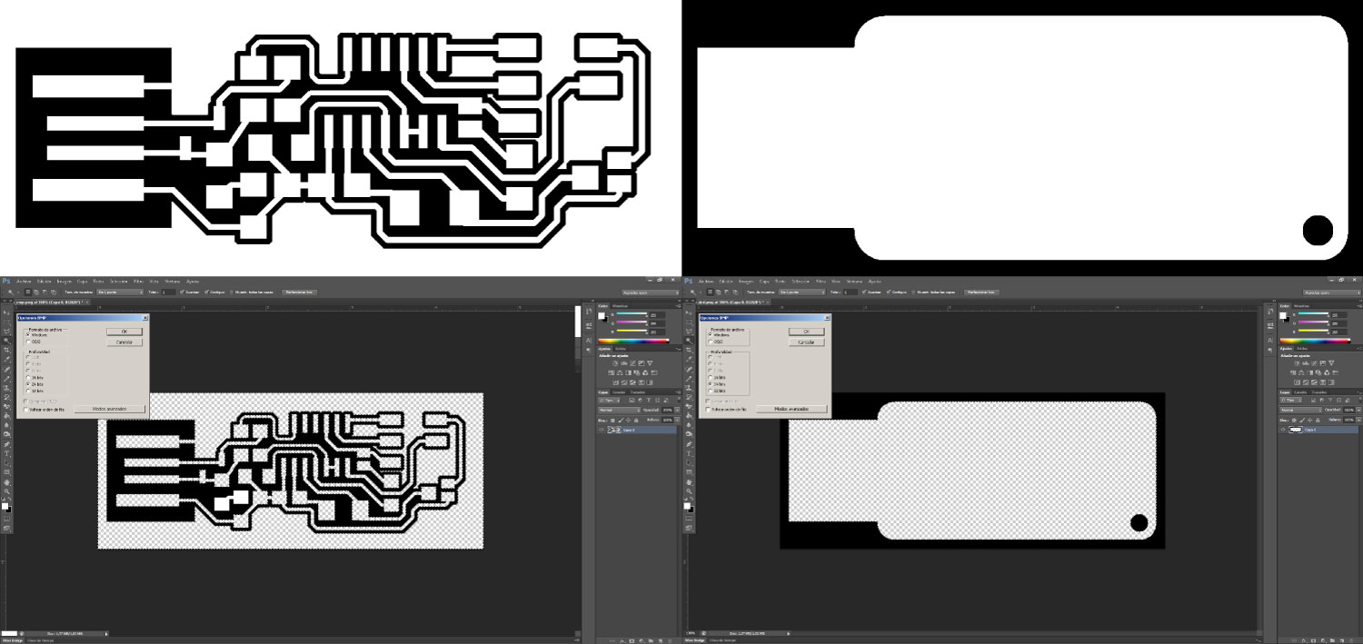
Initially in this assignment, i downloaded the fabIsp .png file for his fabrication process, and as an extra step i edited the files in Photoshop software because the .png file have not the transparencies to open in the Modelo Dr.Engrave software.
Editing of routes file dimension
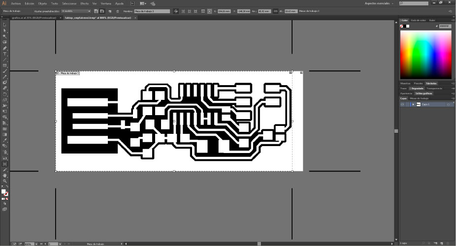
I edited the dimensión of the file in Illustrator software because this is more bigger and don't fit in the contour .png file .
Process cut creation in the Dr.Engrave and 3D Engrave software
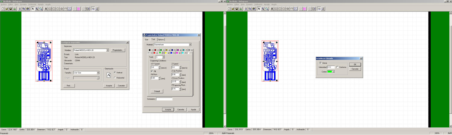
I worked the cut process in the Dr.Engrave, 3D.Engrave software because the fabmodules presented me problems in the installation, but i think that this software is is easy to learn. First the process began with the .bpm import file, then i generated the configurations for the milling routes and the parameters from the fabmodules web software; "x-y" speed=3.0mm/s, fill pitch=0.4mm, z speed=3.0mm, z up position=0.5mm, z down=-00.15, z engraving pitch 0.15mm and an fill parameter to 0.12.
Process of cutting edges
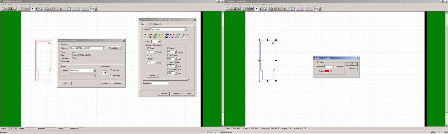
In this part i applied the same configurations that the previous step but with the following changes; fill pitch=0.79mm, z up position=3.00mm, z down positions-2.20mm, z engraving pitch;2.20mm and the fill parameter to 2.
First testing in the Modela MDX 20 machine
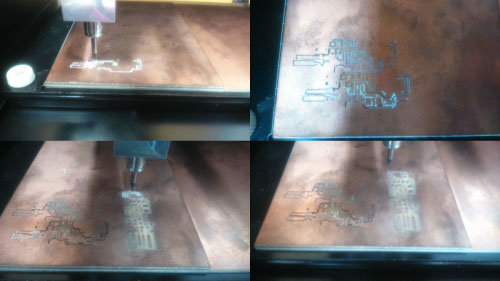
Images of the first tests where the settings vary the depth of milling (zdownposition-zengravingpitch) between 0.2mm and 0.5mm (appearance and corrected for optimal milling).
Prototype boards
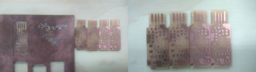
First in the machine calibration i did this web tutorial, then unlike the previous process, i have put the wrong parameters in z down positions and z engraving pitch with the units between 0.2mm to 0.5mm.
Final piece
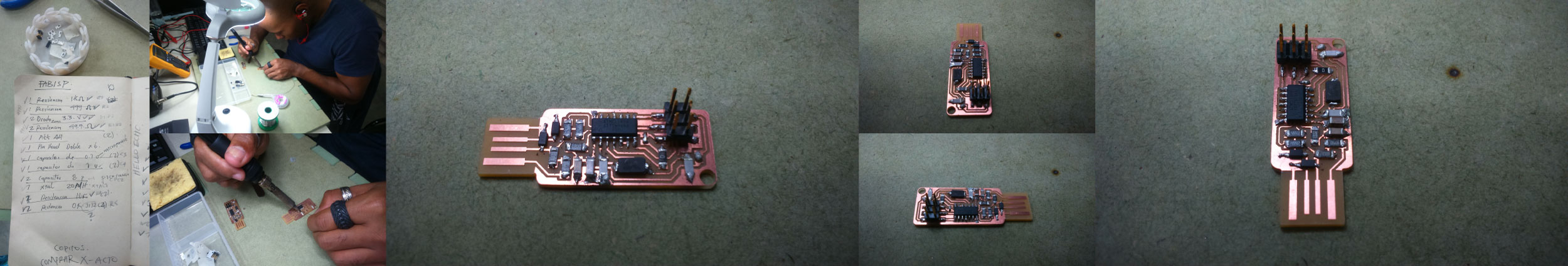
This is the welding process with the component list of the schematic circuit design, i downloaded the list of the tutorials of the fabacademy web page.
FabISP programing
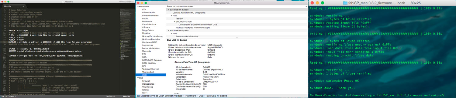
After the fabrications process of the fabISP, i programmed my board by recomendatión of the local instructor and following the steps of the of the web tutorial, in my case i used the parameters for the mac computers.