wk.18-Project development
Initial shape
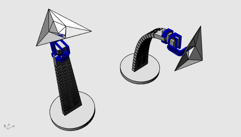
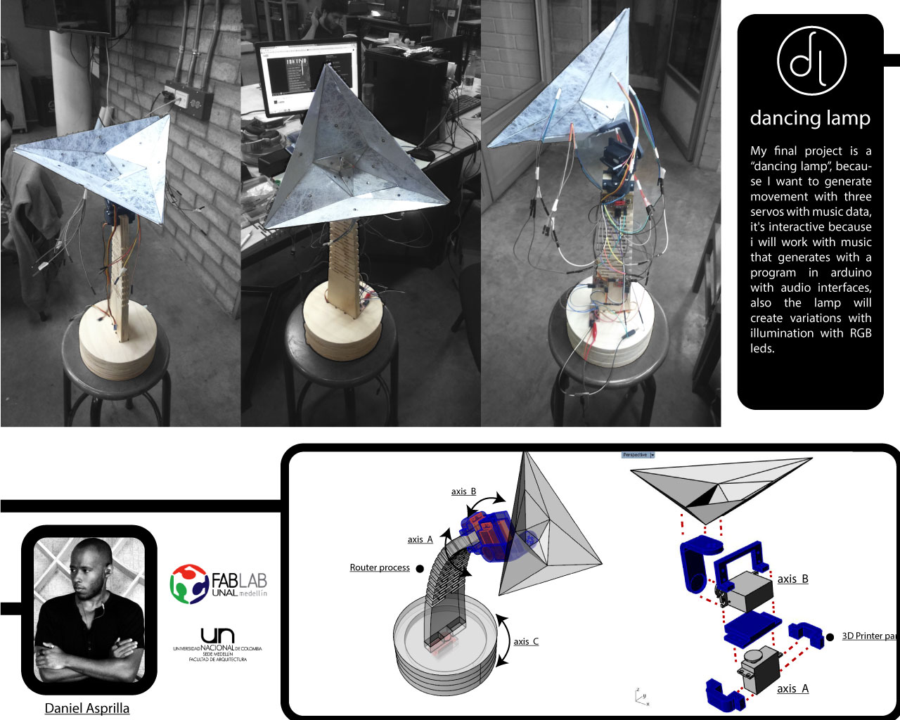
The design shape it was taken of the pattern texture of the previous assignments, also using and drawing digital models for the 3d printer machine "mechanical parts" and the laser cut machine "top shell", all the elements modeling in Rhinoceros software and his plugin grasshopper.
Development of the mechanical parts in the 3d printer machine
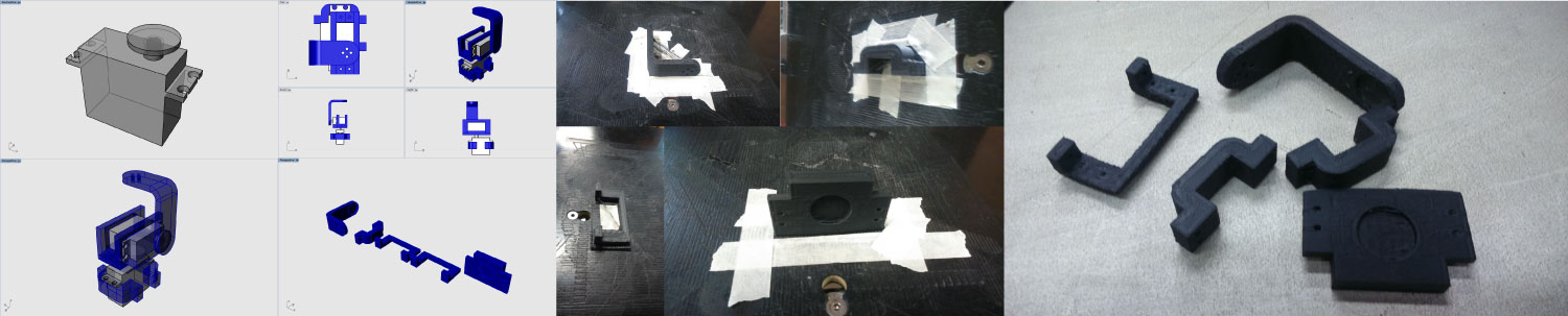
First i modeled the servo motor, for the dimension and necessary tolerance, for the object construccion of the mechanical part of the lamp, all this fabricated in the 3dprinter 3d Touch of the 3d System company.
Development of the shell shape (with the process in the laser cutter machine)
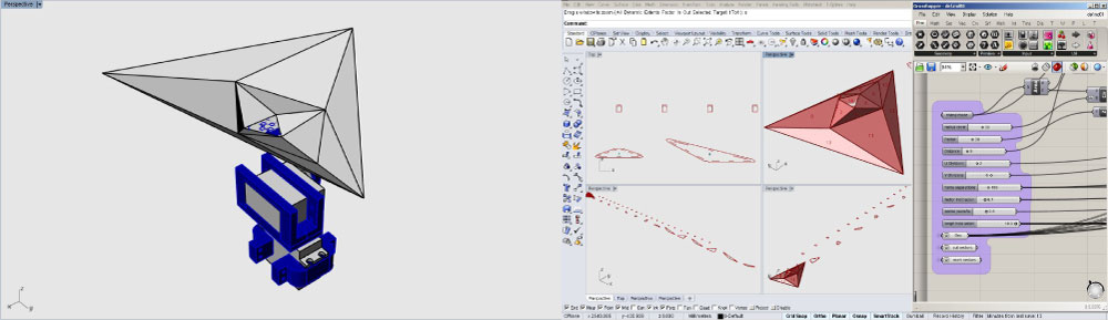
For this process i decided modeling the "top sell" in the rhinoceros plugin grasshopper, because i needed a dynamic and variable model, also for obtain a model that i can modify quickly. all this because i designed the completed piece and the joints system between parts.
Fabrication process of the base

For the wood base fabrications process, i generated the cut vector to send to the Shopbot machine, first thinking in the material Triplex of 18mm, this for testing the effective pattern, for the optimal bend in the possible final model. all this taking the texture pattern developed in Grasshopper complement.
Tools process for the Shopbot machine
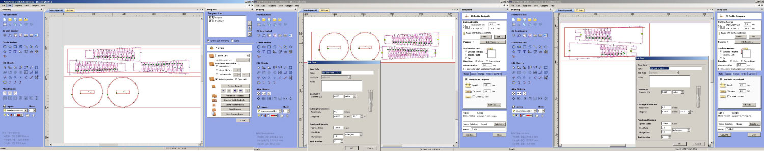
In this point i configured the cuts process to send to the shopbot machine, that in generally was as feed rate= 2.5inch/sec, plug rate=1 inch/sec and cut engraving=2.7mm-3mm, having into account the material, and the waste remnant available in the Fablab.
Base parts & bend test
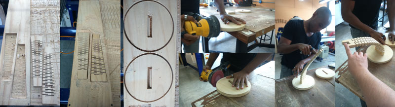
This is the result of the testing, where the first test was very flexible.
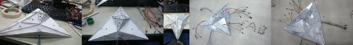
Circuit & test code
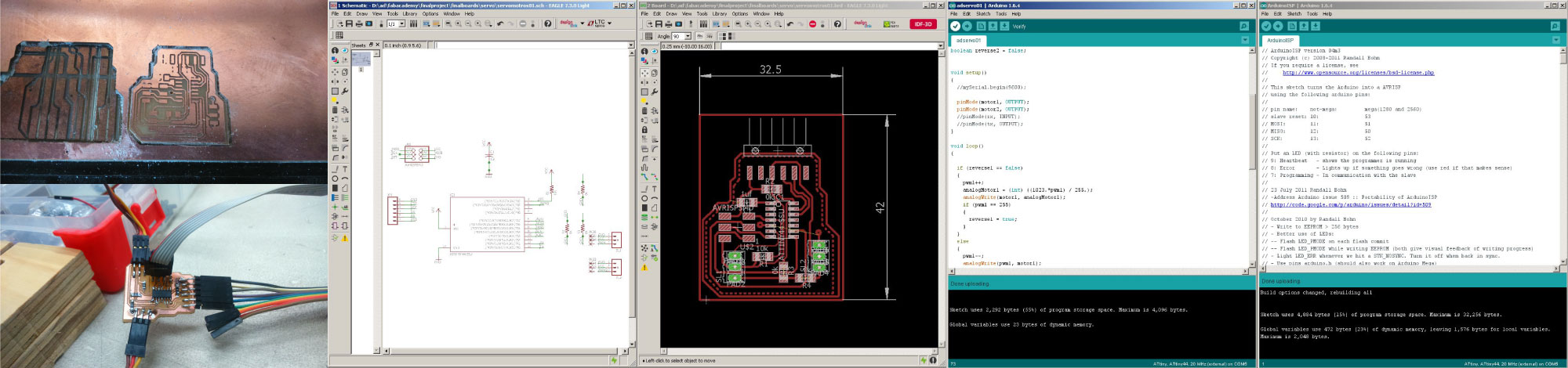
I developed a little circuit for testing the mechanical parts and the two servo motors movement, only in the axis A and B of the Slide to presentation, with the following component list.
- Servo code
int motor1 = 7; //Pin 6 in attyni44
int motor2 = 8; //Pin 5 in attiny44
int i = 0;
int pwm1 = 0;
int pwm2 = 0;
int analogMotor1 = 0;
int analogMotor2 = 0;

boolean reverse1 = false;
boolean reverse2 = false;


void setup()

  pinMode(motor1, OUTPUT);
  pinMode(motor2, OUTPUT);

}

void loop()
{

  if (reverse1 == false)
  {
    pwm1++;
    analogMotor1 = (int) ((1023.*pwm1) / 255.);
    analogWrite(motor1, analogMotor1);
    if (pwm1 == 255)
    {
      reverse1 = true;
    }
  }
  else
  {
    pwm1--;
    analogWrite(pwm1, motor1);
    if (pwm1 == 0)
    {
      reverse1 = false;
    }
  }

  delay(2);

  if (reverse2 == false)
  {
    pwm2++;
    analogMotor2 = (int) ((1023.*pwm2) / 255.);
    analogWrite(motor2, analogMotor2);
    if (pwm2 == 255)
    {
      reverse2 = true;
    }
  }
  else
  {
    pwm2--;
    analogWrite(pwm2, motor2);
    if (pwm2 == 0)
    {
      reverse2 = false;
    }
    delay(2);
  }

  delay(2);

}
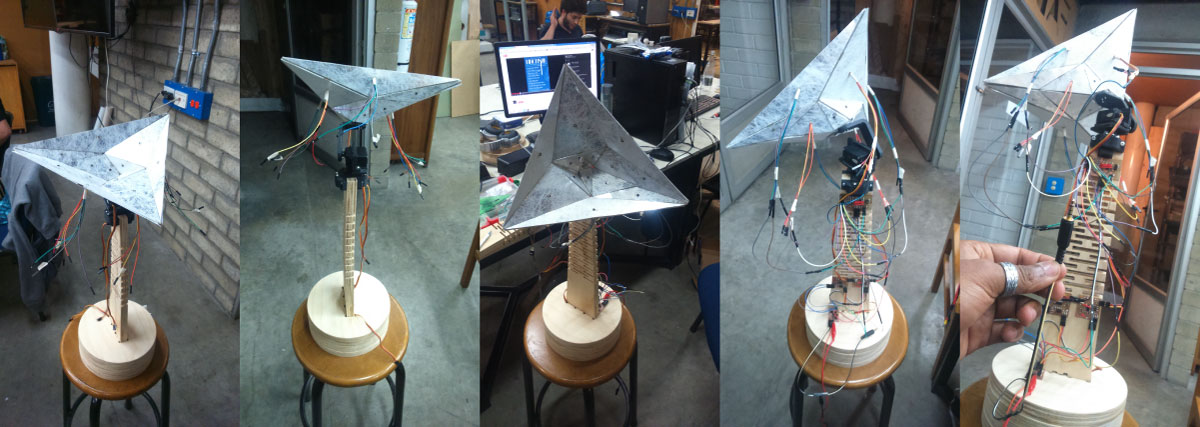
Bend test with the 3D printer parts
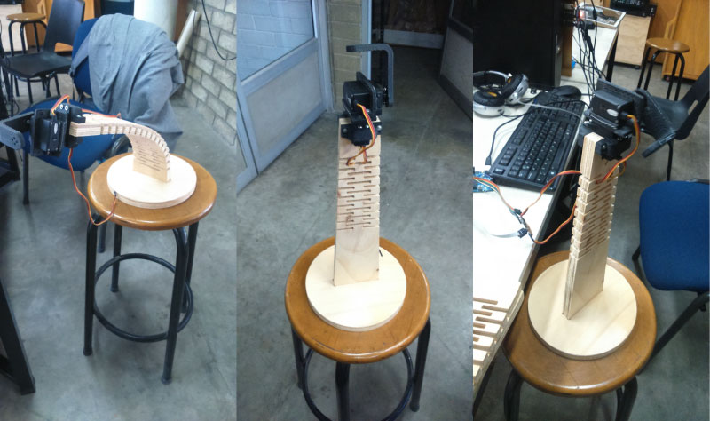
Once produced the base and mechanical 3d printer parts, I tested the behavior of the composition of the manufactured elements.
Movement "dancing" test.01
In this part, i tested the movement with the small program in the manufactured board, that controls two servo motors each one in a independent cycle.
Final LED-RGB circuit
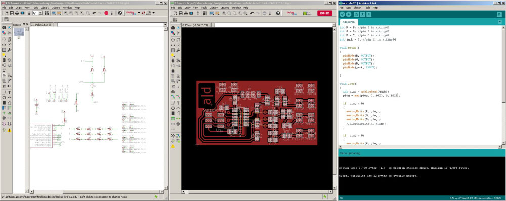
I developed the LED circuit for the dancing lamp final prototype v.01, this board works in generally by providing data in the four inputs of the LED, but I change the possible connections , for generate differents colors, all this with the next component list.
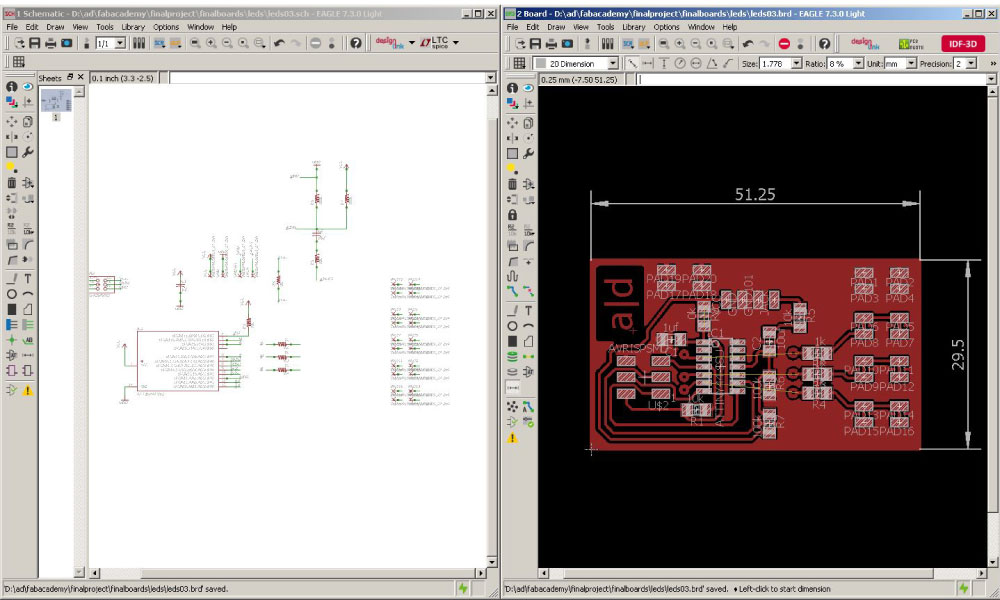
After of test the previous circuit , i could see an error in the board, the circuit has many resistances and the LED illuminate very few, because i confused in the 220 ohm resistance with the 220k resistance, for this I changed of the series resistances "3 of the 100k and 2 of 10k" only for an 1k resistence by LED., now the component list is this:
int R = 9; //pin 3 in attiny44
int G = 8; //pin 5 in attiny44
int B = 7; //pin 6 in attiny44
int jack = 2; //pin 11 in attiny44

void setup()
{
  pinMode(R, OUTPUT);
  pinMode(G, OUTPUT);
  pinMode(B, OUTPUT);
  pinMode(jack, INPUT);

}

void loop()
{
  int plug = analogRead(jack);
  plug = map(plug, 0, 1023, 0, 1023);

  if (plug > 0)
  {
    analogWrite(R, plug);
    analogWrite(G, plug);
    analogWrite(B, plug);
    //digitalWrite(R, HIGH);
  }

  if (plug > 0)
  {
    analogWrite(R, plug);
    analogWrite(G, plug);
    analogWrite(B, plug);
    //digitalWrite(G, HIGH);
  }
  if (plug > 0)
  {
    analogWrite(R, plug);
    analogWrite(G, plug);
    analogWrite(B, plug);
    //digitalWrite(B, HIGH);
  }

  delay(1);
}
Final servo01 circuit
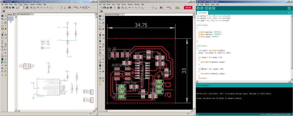
The second final circuit that i developed was the servo motors board, in this I used some aspects and components of the previous test circuit of the servo motors. buy in this case i used a superior bridge for the connection, because i needed clean the other face of the board. the circuit contain the next component list.
int motor1 = 7; //Pin 6 in attyni44
int motor2 = 8; //Pin 5 in attiny44
int jack = 2; //Pin 11 in attiny44

void setup()
{

  pinMode(motor1, OUTPUT);
  pinMode(motor2, OUTPUT);
  pinMode(jack, INPUT);

}

void loop()
{
  int plug = analogRead(jack);
  plug = map(plug, 0, 1023, 0, 255);

  if (plug > 0 & plug < 21)
  {
    analogWrite(motor2, plug);
  }

  if (plug > 21 & plug < 42)
  {
    analogWrite(motor1, plug);
  }
  delay(1);
}
Final servo02 circuit
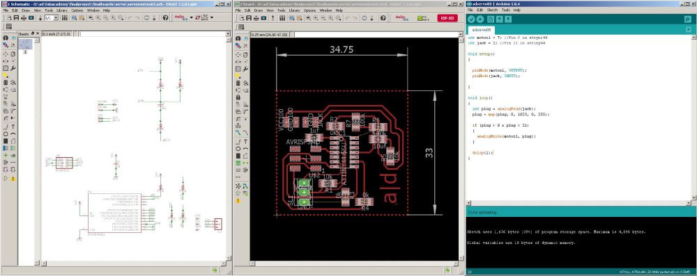
As the previous servo motor circuit only work for two servos, i fabricated other similar board but in this case only for the control of one servo motor, with the next component list.
int motor1 = 7; //Pin 6 in attyni44
int jack = 2; //Pin 11 in attiny44

void setup()
{

  pinMode(motor1, OUTPUT);
  pinMode(jack, INPUT);

}

void loop()
{
  int plug = analogRead(jack);
  plug = map(plug, 0, 1023, 0, 255);

  if (plug > 0 & plug < 21)
  {
    analogWrite(motor1, plug);
  }

  delay(1);
}
Regulator & Jack "Plug" circuit
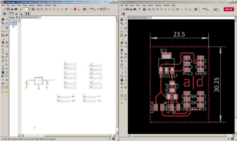
I wanted to control the power and input audio of my project in an board, this by a plug or "Jack " in the case of the audio connection, and in the case of the power by a charger of 5v.
Input data device "plug"
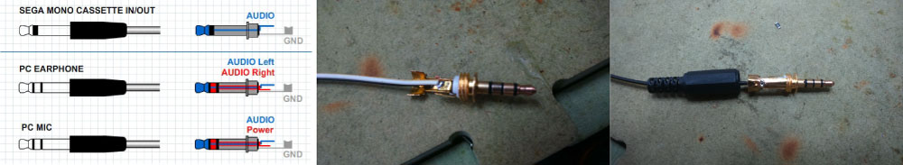
In this image I show how are the plug "jack" connections, also the used schematic guide for the welding process.
Top shell test
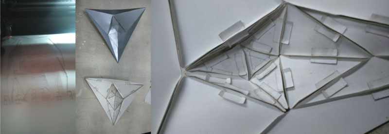
I decided to two shells tests, for the see how work the joint system proposal, and the correct configuration between faces, for the efficient composition of the element.
Shape #1
This is the first approximations of the formal composition for the element, with almost all the parts (in this example missing the boards), I worked with a paper type named "Bindakote Silver".
Shape #2
I chose this shape because is more bigger and also for i worked with other paper type, that illuminate much better than the previous example, in this case i used the paper type named "Twist White".
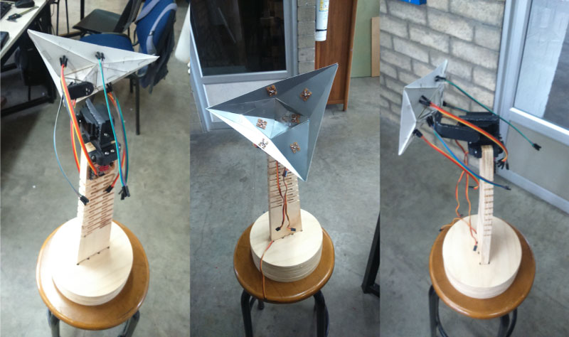
Final shape - "dancing lamp 0.1 beta version"
Movement "dancing" tes.02
Light test.03 "illumination dancing"
Movement "dancing" v.01
Movement "dancing" v.02
In this point I have almost all complete work, only need finish the documentations and test again all the electronic parts, also is important to mention that the develop model is completely a prototype object, and from my point of view this can and needed more and more development, overcoat in the electronic part dispositions, the circuit operation, and the program code to analyze best the music data.
Is very easy, almost everything worked as I did not think, this because I thought first in a code much more bigger with more code libraries for the frequency analyser of music, also that the variations in the illuminations and movement way they would be more marked and variables, and finally that i need in the end make three circuit boards, when initially only thought in one, but thinking in the result of my final project, I concluded that:
- has worked - All the mechanical and structural parts, i think that works well the plywood flexible pattern, also the system base, especially to the 3d printing mechanical parts, also the servo motor circuit board, in the same way the plug or "jack" system connections and somehow the top shell system, but everything this can be improved.
- hasn't worked - For my the RGB LEDS circuits board (by the resistors placing), also the supply circuit because I had to use an external power source, the articulations in the top shell and the 3d printing mechanical system, and especially the wires network, because I used many jumpers and this I cause some shorting problems.
For my in this point the most important question to resolve is, why and how integrate the music, and the data that this generated in the architectural scale "because I´m architect.... yeah.. yeah.. yeah...!!!", either in pavilions, mobile element, panels or prefabricated and most important new materials that respond and receive data of any stimulus, in my case the it produces music.
For my the project is just beginning, in this point i have no intentions to turn it into an object or product to sell,but I'm really interested in to take advantage of all this information to generate more, because I have clear potential of the project not as an object of sale, if not as a future investigations project, of possible architectural interventions and for this reason I need to explore both the "software" and "hardware" possibilities, as a mentioned in previous occasions. With this, I continue to believe that my final project is more a information generation process, that you will be generating interventions, workshops and possibilities to create new spaces, that in short or long term it will generate profit.
First and apart from the obvious to me that are the softwares and interfaces learned as antimony, freecad, Blender among others, also the application of the different method and fabrications system, and the range and possibility to use new materials, the most important for me,is that i am really ignorant "in a good way"... second that in order to implement, make or guide, you need know, and last that definitely is completely necessary know of programing for discover and develop incredible things. also and related to the previous comments, i think that this experience also give me three important things: