wk.10/11-Imput & Output devices
Generalities
In this assignment i have the opportunity of explore some possibilities of my final project, because I think work with the sound data and how this can be used for light variations, in this sense, I plan to design to board that read a analog microphone data, and with this lights a LED system.
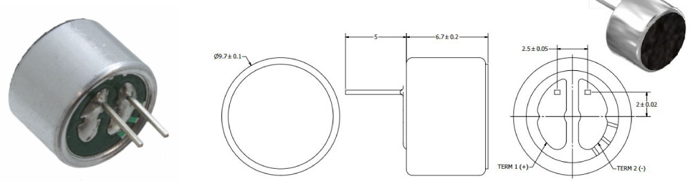
- As input device i used a analog microphone, because the data range is more easy to understand for me and the ease of connections, also because i think work wit the music and this is an initial way to start to work with the audio data.
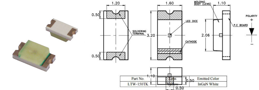
- As output device I work with the three LED , because my intention is create a lamp prototype, and that better way that work with the LED, for testing as the audio data "music data in the future" lights the LED in some of their ranges.
- I designed the board thinking in how integrate an input and an output, for this i work with the analog microphone and this in the program that i created gives me a range of data between 0 to 1023, with this data and in the testing process, I found that the best working range was of 440 and 420, and then I thought of the code, and this works when the microphone detect a range between 440 to 420, the LED switched on, and when they are not in this range are off.
Circuit drawing
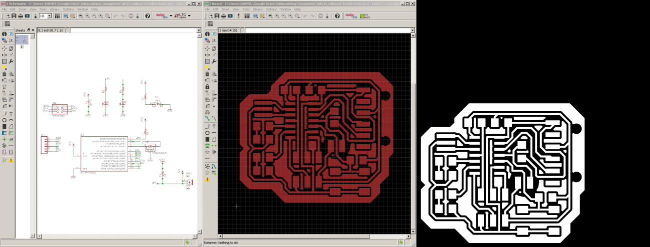
First i drawed the circuit in the Eagle CAD software, and taking reference the sketch of the hello.eco board but adding something components as resistor the 1k, 2 leds (because i wanted to work the output assignment in parallel) and one microphone. Is need export the board in the .bpm extension for to work on the Dr.Engrave software.
Milling parameters
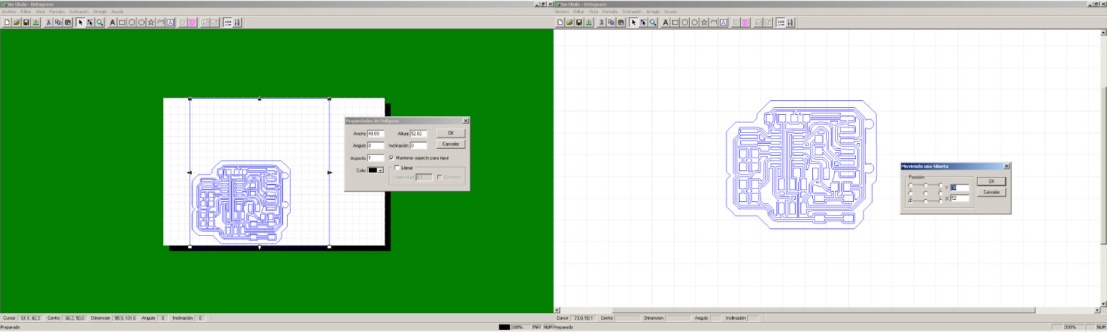
Once checked the board sketch, I did the milling configurations in the Dr.Engrave software,initially adjusted the following parameters; polygon property (scale), and the position or location in the workspace (points in the "x,y" axes).
More configurations
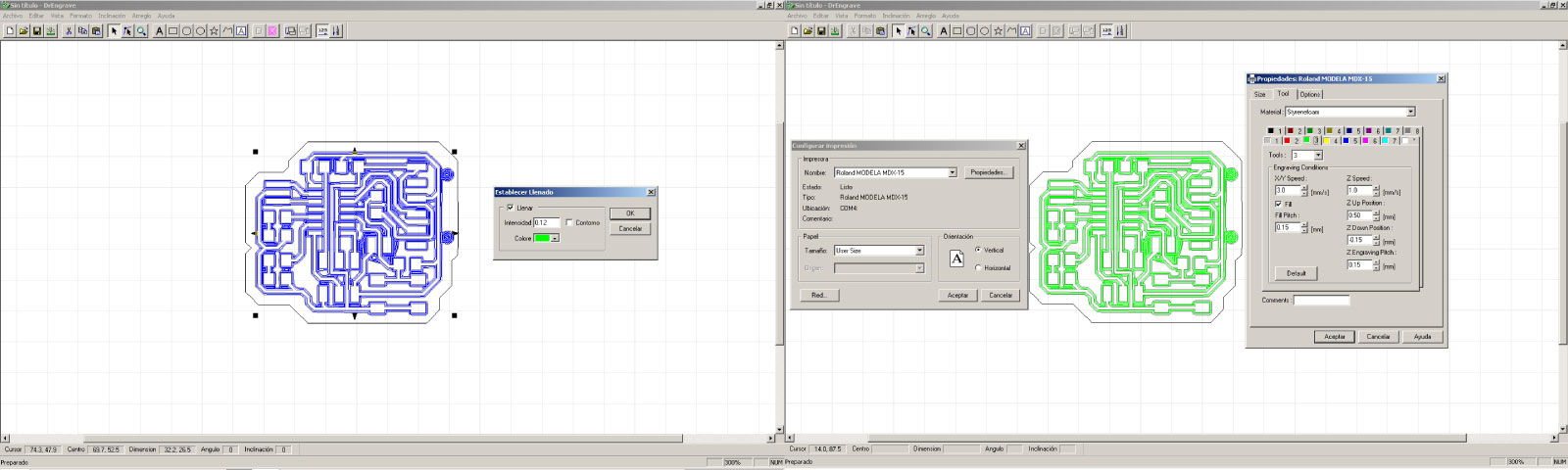
Following the previous steps, i created the fill pattern to the milling process, with the settings; fill=0.12 (software unit factor), selected the machine type to work (Modela MDX 15/20) and the following tool parameters, "xy" speed=3.0mm/s, z speed=1.0mm/s, z up position=0.5mm, z down position=-0.15mm, z engraving pitch=0.15mm and the fill pitch=0.15mm (this is directly related to the tool diameter dimension 1/64”).
Contour milling
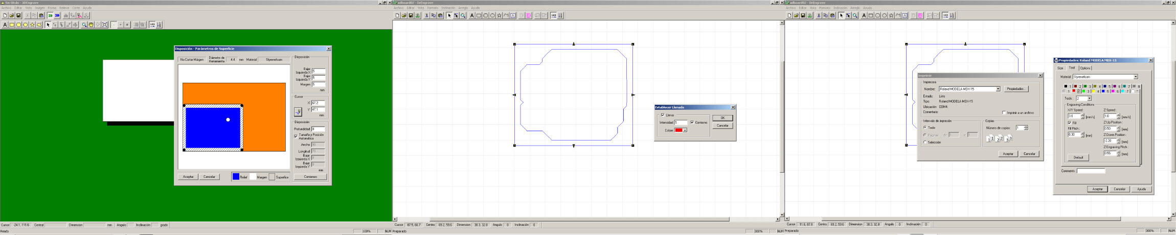
In this case and working the same settings of the previous process, I choose the tool position for the z axis location, then the fill pattern=5 (select the contour options) and finish with the same tool configurations but changing the following points; z down position=-2.20mm, z engraving pitch=0.55mm and fill pitch=0.3mm (this is directly related to the tool diameter dimension 1/32”)
Milling process in the Modela machine
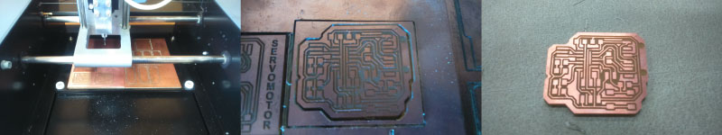
In this milling process only include that the routes process and the contour process were sent as a separate to machine.
Final piece
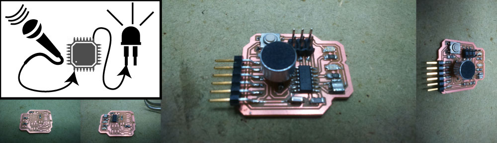
This is the welding process with the set of parts or components, with the following component list.
The final circuit board, in my opinion have a component that does not need, "the buttom", because my program or my intentions is lights the LED system with the microphone, this is needless component.
Loading code...
I write the code thinking in two aspects, the first that the microphone detect any changes sound, and this lights the LED system, and second having in account the range read of the microphone, because is necessary know the microphone type, and which is his work range, to establish a numerical factor between two data for on and off the LED system, with this I establish in the code that the LEDS lights in a value between "438-440", according to testings with the microphone.
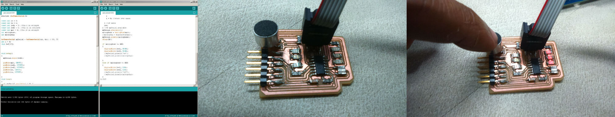
#includeconst int rx = 0; const int tx = 1; const int led1 = 7; //Pin 6 in attiny44 const int led2 = 2; //Pin 11 in attiny44 const int mic = 3; //Pin 10 in attiny44 int microphone; int micropdig; SoftwareSerial mySerial = SoftwareSerial(rx, tx); // RX, TX int i = 0; char buf[12]; void setup() { mySerial.begin(9600); pinMode(mic, INPUT); pinMode(led1, OUTPUT); pinMode(led2, OUTPUT); pinMode(rx, INPUT); pinMode(tx, OUTPUT); } void loop() { if (mySerial.available() > 0) { buf[i] = mySerial.read(); if (int(buf[i]) == 13 || int(buf[i]) == 10 ) { //If Carriage return has been reached mySerial.println(buf); for (int x = 0; x <= 10; x++) { buf[x] = ' '; } i = 0; //start over again } i++; } mySerial.available(); microphone = analogRead(mic); mySerial.println(microphone); delay(50); if (microphone >= 440) { digitalWrite(led1, HIGH); digitalWrite(led2, HIGH); } else if (microphone <= 420) { digitalWrite(led1, LOW); digitalWrite(led2, LOW); } }
This code does not work effectively for two reason, the principal is the elevated range factor of 20 "440 - 420", and because the microphone and with this program needed much noise for work, and the second reason is the work environment, this because i worked in the Fab Lab with the all machines and all people team, and this generated noise and "contaminated" in some way the work space for the "experiment", for this i decided for energy efficiency of time and resources changes a little the code, and find the correct factor for lights the LED system.
#includeconst int rx = 0; const int tx = 1; const int led1 = 7; //Pin 6 in attiny44 const int led2 = 2; //Pin 11 in attiny44 const int mic = 3; //Pin 10 in attiny44 int microphone; int micropdig; SoftwareSerial mySerial = SoftwareSerial(rx, tx); // RX, TX int i = 0; char buf[12]; void setup() { mySerial.begin(9600); pinMode(mic, INPUT); pinMode(led1, OUTPUT); pinMode(led2, OUTPUT); pinMode(rx, INPUT); pinMode(tx, OUTPUT); } void loop() { if (mySerial.available() > 0) { buf[i] = mySerial.read(); if (int(buf[i]) == 13 || int(buf[i]) == 10 ) { //If Carriage return has been reached mySerial.println(buf); for (int x = 0; x <= 10; x++) { buf[x] = ' '; } i = 0; } i++; } mySerial.available(); microphone = analogRead(mic); mySerial.println(microphone); delay(50); if (microphone >= 444) { digitalWrite(led1, HIGH); digitalWrite(led2, HIGH); } else if (microphone <= 438) { digitalWrite(led1, LOW); digitalWrite(led2, LOW); } }
Here in this case i find the close range of 6 "438 - 444" for the correctly work of my code and board, for this i simply changed several times the factors until I found one that gave me the approximate answer.
Program test