Skulina Hlif Kjartansdottir
How to make [almost] anything
Week 7: Embedded programming
This week we will learn about embedded programming, Embedded systems programming is the programming of an embedded system in some device using the permitted programming interfaces provided by that system. This is our agenda - we will be learning more about different aspects of embedded programming, such as architecture, memory, peripherals, word sizes, families of microcontrollers, the different vendors of components, AVR processors, data sheets, packages, clocks, in-system development, programmers, assembly languages and C, which we will be using to program our board. We will also learn about host communication, IDE, different boards, interpreters and STM32 programmers.
Week 7: Assignment
The assignment for this week is to read a microcontroller data sheet and to program our board to do something, with as many different programming languages and programming environments as possible.
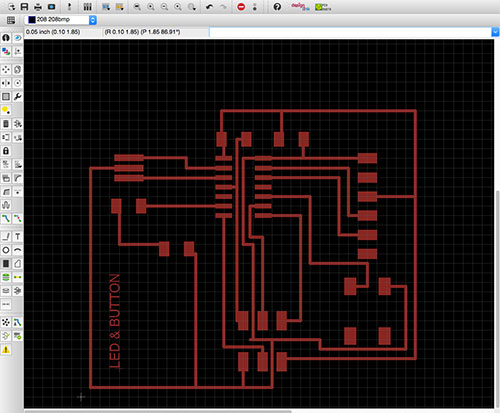
Last week I created the hello.ftdi.44 circuit board employing the eagle software. This board will now serve as the experimental board for the embedded programming. The aim is to write code for the microcontroller on the board and make it do something.
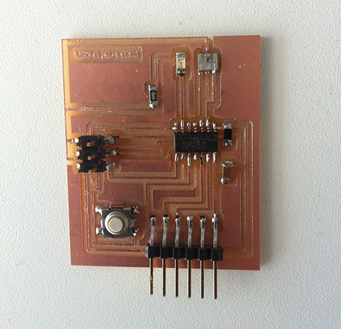
The actions refer to the design of the board:
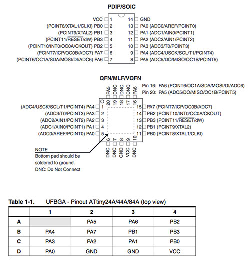
The basis for understanding the assignment is to read the datasheet of the AVR microcontroller, ATtiny44A, a low-power CMOS 8-bit microcontroller based on the AVR enhanced RISC architecture. This enables us to understand pin configurations of the board...
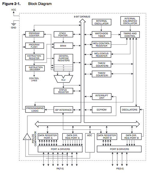
...as well as the block diagram in order to understand the architecture of the ATtiny44!:
The task we set us was to light the LED, by using the button on the board. When pressing it, we send voltage to the LED light. The microcontroller has a built-in pull-up resistor and how we turn this on and off is down to the programming. In this context the port, pin and DDR (data direction register) are important, as the port is used if you want to output something (1-turn on, 0-turn off). The output is set on PA2 and the input on PBA. The DDRA (switch) - set the PA2 to 1 (electricity on).
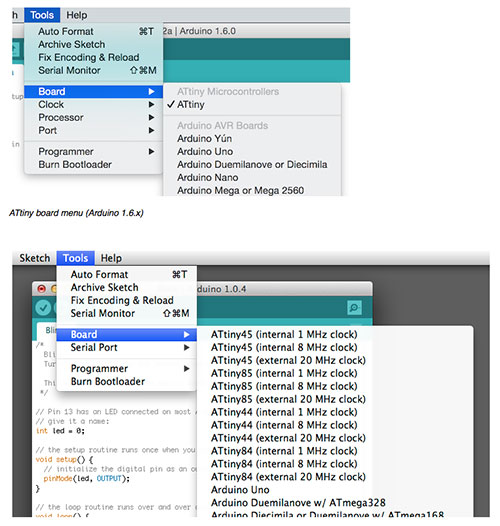
Starting the programming I followed a tutorial on high-low tech – Programming an Attiny w/ Arduino 1.6. I also made use of the reference for finding commands. I downloaded the Arduino 1.6; ide-1.6x.zip, unzipped it and located the content of the ATtiny folder in a hardware folder that I created in Documents/Arduino/hardware/. I then restarted the Arduino development environment. Next I set Tools – Board – Attiny. Then I specified the Clock and the Processor – Attiny (internal 20 MHz clock).
If you connect a LED between 0 and ground, the light should blink. In my case it did not. Investigating the problem I found that the LED was not positioned the right way around. This was tested with a multimeter and consequently the LED was resoldered into the correct position.
I now connected the ATtiny and ISP to the computer for power and started the programming. I opened the Blink file (File-Example-01.Basics-Blink) and changed the value of the digital pin.
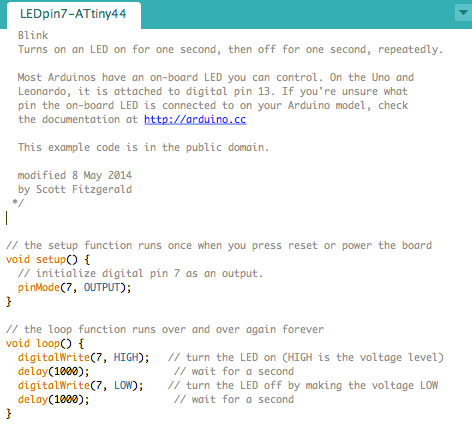
Next I uploaded the arduino sketch to the board. I then completed the following steps: Then select Tool - Burn Bootloader – Done burning bootloader. Upload again.
File – examples – digital – button. Change the value for buttonPin og ledPin:
To activate pull-up resistor in the microcontroller I added this to setup (last line):
Upon resoldering it onto the board and re-testing it did, luckily Work:
Plans for next Week
Try to get a little more programming done.
Notes
My Notes from this week.