Skulina Hlif Kjartansdottir
How to make [almost] anything
Week 11: Output devices
This week we carrying on with electronics and learn about output devices. This is our agenda for the week.
Week 11: Assignment
The assignment for this week is to add an output device to a microcontroller board that we design and to program it to do something. I wanted to design a speaker board with a sensor that senses change in natural daylight. When the light increases a sound can be produced, that increases in intensity with the light exposure. It needs to:
1. measure the intensity of light (photoresistor)
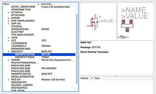
2. drive the speaker (mosfet)
3. have an energy resource (battery-9v)
4. drive the activity (microcontroller)
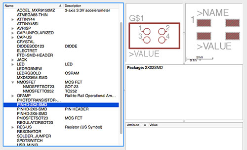
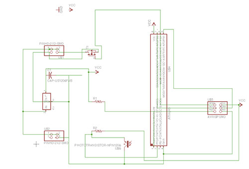
This speaker board has the same components as my light input board (minus the FTDI-SMD_HEADER) with the addition of a mosfet (NMOSFETSOT23 = MOSFET (T1 N)) and 2 Pinheads (PINHD-2x2-SMD), The MOSFET is metal–oxide–semiconductor field-effect transistor (MOSFET, MOS-FET, or MOS FET), a type of transistor used for amplifying or switching electronic signals.
The Pinheads connect the speaker and power.
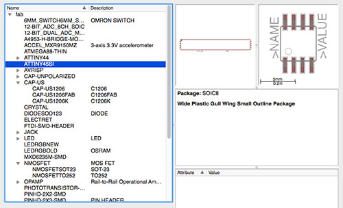
The main component is the microcontroller, the ATtiny45SI, which reads the voltage and adds, subtracts and sends information around, changing the course of action. It acts upon any messages that it receives.
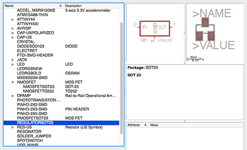
A regulator is a device for controlling the rate of working of machinery and a voltage regulator is designed to automatically maintain a constant voltage level.
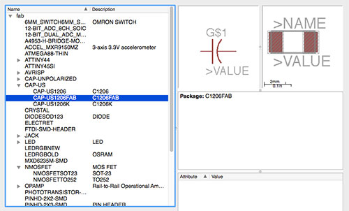
The capacitor (CAP-US1206FAB – C1206FAB) acts as a kind of a power reserve, stores energy and can release it quickly. Also helps mediate the problems of brown-out (power failure or dip in the current).
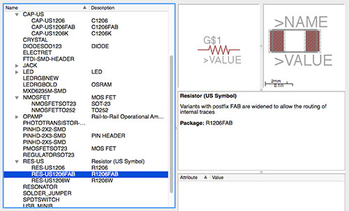
The board has 2 resistors. The R1 (RES-US = R1 10k (RES-US1206FAB – R1206FAB)). R1 is a pull-up resistor, pulls upp to 5v and when the voltage on the line is pulled up to 5v. Is needed on the reset line to make sure the microcontroller does not reset.
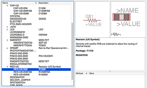
The R1 resistor (RES-US = R2 49.9k (RES-US1206 – R1206) = R2 49.9k) limits the amount of current, with division of voltage.
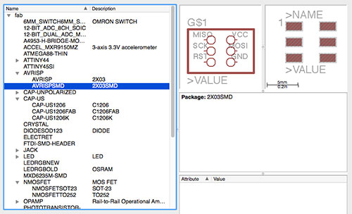
The AVRISPSMD = J1 ISP (in system programming) is used as a connector, allowing the board to be programmed, through a cable.
Finally, the Phototransistor (T1) acts an optical sensor, measuring the intensity of light.
![]()
My output board was based on the Hello.speaker.45.cad board but I added the additional components needed. The schematic looks like this:
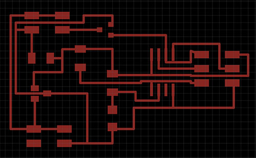
The drawing of the board went through some iterations and changes, that finally resulted in this board:
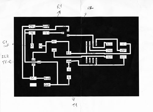
I used this sketch as a basis for soldering:
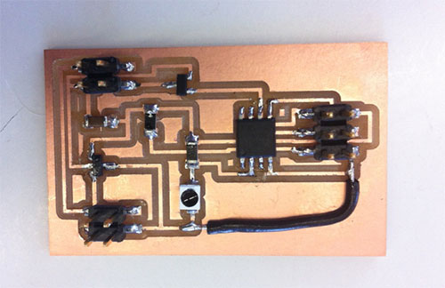
I had some adventure with soldering, resulting in me having to connect between circuits with a wire, also cutting of circuits with a knife to ensure disconnection. I made a mistake in the schematic which resulted in a workaround, a wire that was soldered onto the board.
The board was then connected to the programmer board/computer and the speaker and battery were also connected to the board, with a connector to their relevant pins (The wires need to be connected to ground and vcc):
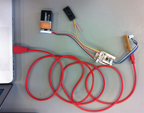
In Arduino 3 components were set - the board to ATtiny, processor - to 45 and Clock to internal 8Mhz. The speaker is connected to the battery and the mosfet, which acts as a switch. Microcontroller can open or close it. The other side of the mosfet is connected to ground. When the microcontroller closes the switch then the speaker reacts (there is a magnet and around it is a coil, with a gap in between. This wire is connected to the coil. The magnets contracts and there is a pull of the surface of the speaker, moving air. This creates a tone). The code produced was:
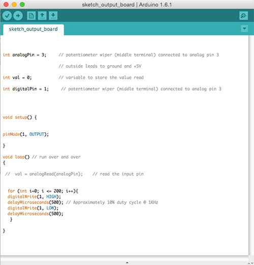
The output to the speakers was a beeping sound that was produced continuously, but later amended with a delay. I experimented with a melody test and the tone() command, but not with much success.
Plans for next Week
Study more programming and the Arduino references.
Notes
My Notes from this week.