Skulina Hlif Kjartansdottir
How to make [almost] anything
Week 4: Electronics Production
This week we will learn about electronics production – a new subject for me. This is the agenda and we will be tackling PBC fabrication, PBC materials, board houses, components and breadboards and the assembling of those. We will be using the fabmodules and a milling machine (Roland Modela) and some other gadgets to achieve the tasks.
Week 4: Assignment
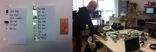
The assignment for this week is to make a FabISP in-circuit programmer - stuffing the board and attaching the relevant components to it. The FabISP is an in-system programmer for AVR microcontrollers, which is designed for production within the FabLab. It allows you to program the microcontrollers on other boards that we will make. We will also learn how to program the FabISP later on.
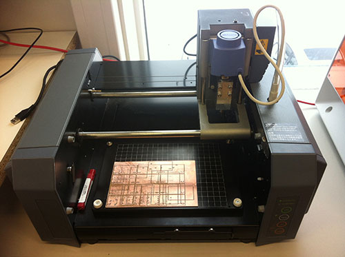
I prepared for the work by watching this FabLab video, giving work instructions on how to mill PCBs on the Roland Modela machine.
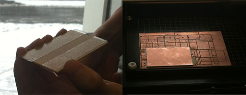
We started prepairing the material for the board before milling by taping it with double-stick-tape. Then the board was taped to a sacrificial layer on the milling machine, which can be cut into when the board is finally cut out.
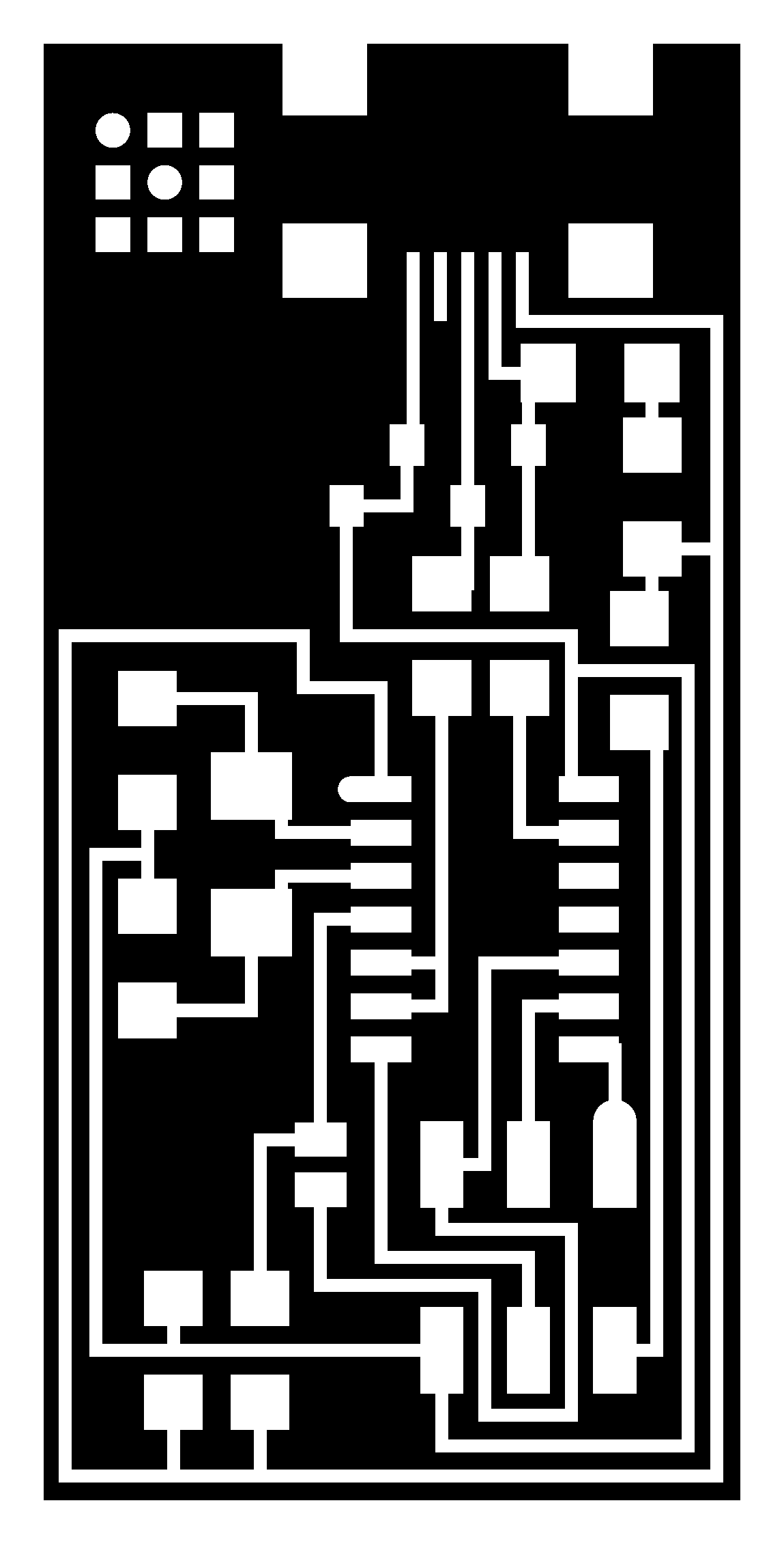
Then we activated the fabmodules and adjusted the settings in preparation for milling. A .png image file (traces) is loaded in the Fabmodules and rml setting chosen.
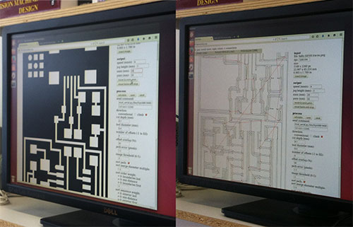
The home settings need to be adjusted as well as the xmin/ymin, placing the starting point of the endmills cutting the board. The endmills need to be handled carefully, making sure they do not fall from the chuck and damaging the cutting end, while adjusting. The 1/64 (finest) endmill is used to cut the traces, but the 1/32 to cut the board out. The cut for the traces is calculated on the fabmodule window. When the xmin/ymin is set the tool is lowered to the surface of the board material and tightened. Then the message from the fabmodule window can be sent to the Roland Modela machine to start the cut.
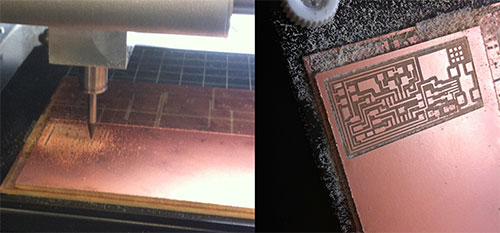
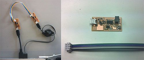
The cutting went smoothly and soon we all had nice boards ready for the stuffing with the relevant components.
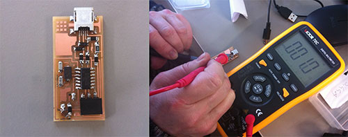
We then started assembling the various components and soldered them in place onto the boards. The soldering of my board was mostly successful, but one copper foil became undone, but we found a work-around for it.
We had to test the soldering and the functionality of the boards with a digital multi-meter, to make sure the conducting was achieved:
Finally, we programmed the board, creating the FabISP in-circuit programmer.
This action is further documented in my notes.
Plans for next Week
Learn more about programming...and Python!
Notes
My Notes from this week.